The Design and Prototype Manufacture of a Planetary Gear Reducer
Tzu-Hsia Chen
1,*, Long-Chang Hsieh
21Department of Mechanical Engineering, Minghsin University of Science and Technology, Taiwan, ROC
2
Department of Power Mechanical Engineering, National Formosa University, Yunlin, Taiwan, ROC
Received 02 May 2018; received in revised form 28 May 2018; accepted 05 August 2018
Abstract
The gear reducer of the power system can be ordinary spur gear reducer, worm and worm gear reducer, or
planetary gear reducer. Due to the compact size, light weight, and multi-degrees of freedom; planetary gear reducers
are commonly used in various transmissions. One of its applications is used as the gear reducer for industrial purpose.
The reduction ratios of 1-stage planetary gear reducers are limited to 3 ~ 10. This paper focused on the design and
prototype manufacture of a 1-stage planetary gear reducer. First, according to the concept of train value equation, the
planetary gear reducer with reduction ratio 4 is proposed. Based on the involute theorem, the gear data of the
planetary gear reducer are obtained. Finally, based on the results of kinematic design and meshing efficiency
analysis, the integrated design of the planetary gear reducer was carried out and the prototype was manufactured to
verify the design theorem. The results of this paper can be used as a reference for engineers to design the gear
reducers for industrial purpose.
Keywords: engineering design, planetary gear reducer, prototype manufacture, train value equation
1.
Introduction
Traditionally, the reduction ratio of an ordinary spurs gear pair, worm and worm gear pair, and 1-stage planetary gear train
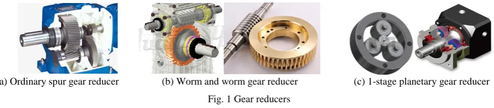
is limited to 4~7, 10~100, and 3 ~ 10, respectively. Figs. 1 (a)-(c) show the ordinary spur gear reducer, worm and worm gear
reducer, and 1-stage planetary gear reducer, respectively. Due to the reason of the compact size, light weight, and
multi-degrees of freedom; planetary gear reducers are commonly used in various transmissions. One of its applications is used
as the gear reducer for industrial purpose.
(a) Ordinary spur gear reducer (b) Worm and worm gear reducer (c) 1-stage planetary gear reducer
Fig. 1 Gear reducers
In the past, planetary gear trains were the subjects of intensive researches directed at kinematic analysis [1-5], kinematic
design [6-13], and meshing efficiency analysis [14-19]. The purpose of this paper is to propose a planetary gear reducer with
reduction ratio Rr=4 for industry purpose. The results of this paper can be used as a reference for engineers to design all kinds
of planetary gear reducers. The research result can also provide the application experiences for the transmission design practice
course.
*Corresponding author. E-mail address: [email protected]
2.
Train Value Equation
For a planetary gear train, shown in Fig. 2, we denoted the first sun gear as i, the last sun gear as j, and the carrier (arm) as
k, respectively. The train circuit can be denoted as (i, j; k); the relationship among ωi, ωj, and ωk can be expressed as:
Fig. 2 Planetary gear train
0
)
1
(
ji j ji ki
(1)Here ξjiis the train value of sun gear j to sun gear i. The sum of the coefficients of Eq. (1) is equal to 0, i.e., 1
ji(
ji1)0.For a planetary gear train with the single train circuit, there are three members (i, j, and k) can be adjacent to input shaft, output
shaft, and frame. If sun gear j is adjacent to the frame (ωj=0), and sun gear i is adjacent to the input shaft (ωi=ωin), and carrier k is adjacent to the output shaft (ωk=ωout), according to Eq. (1), its reduction ratio (Rr) can be written as:
1
(
1)
1
ji in i
r ji
out k
R
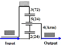
(2)For a planetary gear train with ξji < 0, the reduction ratio Rr > 1. For the planetary gear reducer shown in Fig. 3, let Z2=24,
Z5=24, and Z3=72, then there is the train value ξ32=-3. Since the sun gear 3 is adjacent to the frame (ω3=0), and the sun gear 2
is adjacent to the input shaft (ω2=ωin); the carrier 4 is adjacent to the output shaft (ω4=ωout), according to Eq. (2), its reduction
ratio Rr = 4.
Fig. 3 Planetary gear reducer with reduction ratio Rr = 4
3.
Latent Power Theorem and Meshing Efficiency
For a planetary gear train with sun gear i, ring gear j, and carrier k. Ti, Tj and Tk are the torques of members i, j and k, respectively. Since they rotate around the same axis, and according to the torque balance, we have:
0
j ki
T
T
T
(3)Furthermore, the latent powers of sun gear i and sun gear j relative to carrier k ( 𝑃𝑖𝑘 and 𝑃𝑗𝑘 )are defined as :
i k
i k i T
P
(4)
j k
jk j
T
P
(5)𝜂𝑖𝑗𝑘 ( 𝜂𝑗𝑖𝑘 ) is the meshing efficiency of planetary gear train; if the latent power is transmitted from sun gear i (sun gear j) to sun
gear j (sun gear i), when carrier k is relatively fixed. Based on the concept of latent power[14-19], the relationship between k i P
and k j
0 P and 0 P for P P k j k i k ij k i k
j
(6)0 P and 0 P for P P k j k i k ji k j k
i
(7)The meshing efficiency of the planetary gear train is defined as the ratio of output power to input power, i.e.,
( ) out m PGT in P P
(8)
According to Eqs. (3) ~ (8), the meshing efficiency of planetary gear reducer can be expressed as follows:
( ) 1 1 k ji ij m PGT ji (9)where 𝜂𝑖𝑗𝑘 ( 𝜂𝑗𝑖𝑘 ) is the meshing efficiency of planetary gear train; if the latent power is transmitted from sun gear i (sun gear j)
to sun gear j (sun gear i) when carrier k is relatively fixed. The meshing efficiency of ordinary external gear pair (m(ex)) and
internal gear pair(m(in)) can be expressed as [20-22]:
2 2
( ) 1 1
1 1
1 1/
1 [ ]
2 2
a
r r
m ex A R
A R f R f
(10) 2 2( ) 1 1
1 1
1 1/
1 [ ]
2 2
a
r r
m in A R
A R f R f (11)
where Rr is the reduction ratio of gear pair, βA1 and βA2 are the angles of approach of driving and driven gears, fa and fr are the
average friction coefficient of approach and recess.
For external (internal) gear pair, the meshing efficiencies are between 99.2% ~ 99.6% (99.7% ~ 99.9%). For the planetary
gear reducer in Fig. 3, if the meshing efficiencies of external and internal gear pairs are 0.994 and 0.998, then the meshing
efficiency of 𝜂𝑖𝑗𝑘 is k 0.994 0.998 0.992 ij
. Then, according to Eq. (9), the meshing efficiency of the planetary gear reducer
is99.4%. Based on the above results, we concluded that the meshing efficiencies of planetary gear reducers are very good.
4.
Engineering Design and Prototype
In the following paragraph, the planetary gear reducer, shown in Fig. 3, is the example to illustrate how to design the
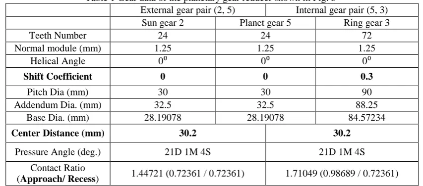
planetary gear reducer. Table 1 shows some important gear data of this feasible design example.
Table 1 Gear data of the planetary gear reducer shown in Fig. 3
External gear pair (2, 5) Internal gear pair (5, 3) Sun gear 2 Planet gear 5 Ring gear 3
Teeth Number 24 24 72
Normal module (mm) 1.25 1.25 1.25
Helical Angle 0⁰ 0⁰ 0⁰
Shift Coefficient 0 0 0.3
Pitch Dia (mm) 30 30 90
Addendum Dia. (mm) 32.5 32.5 88.25
Base Dia. (mm) 28.19078 28.19078 84.57234
Center Distance (mm) 30.2 30.2
Pressure Angle (deg.) 21D 1M 4S 21D 1M 4S
Contact Ratio
(Approach/ Recess) 1.44721 (0.72361 / 0.72361) 1.71049 (0.98689 / 0.72361)
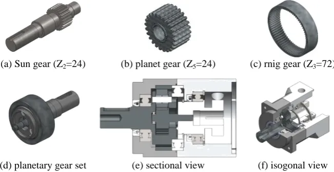
According to the gear data in Table 1, the engineering design drawings shown in Figs. 4(a), 4(b), 4(c),and 4(d) are sun
gear 2 (Z2=24), planet gear 5 (Z5=24), ring gear 3 (Z3=72), and planetary gear set of planetary gear reducer. Figs. 4(e) and 4(f)
(a) Sun gear (Z2=24) (b) planet gear (Z5=24) (c) rnig gear (Z3=72)
(d) planetary gear set (e) sectional view (f) isogonal view
Fig. 4 Engineering drawing of planetary gear reducer
Figs. 5(a), 5(b), 5(c), and 5(d) show the corresponding prototype photo of sun gear 2 (Z2=24), planet gear 5 (Z5=24), ring
gear 3 (Z3=72), and planetary gear set of planetary gear reducer. Figs. 5(e) and 5(f) show its corresponding prototype photo of
1/2 Section view and isometric view.
(a) Sun gear (Z2=24) (b) Planet gear (Z5=24) (c) Rnig gear (Z3=72)
(d) Planetary gear set (e) Sectional view (f) Isogonal view
Fig. 5 Prototype photos of planetary gear reducer
5.
Conclusions
The reduction ratios of 1-stage planetary gear reducers are limited to 3 ~ 10. This paper focuses on the integrated design and prototype manufacture of the planetary gear reducer (with reduction ratio Rr=4) for industry purpose. According to the kinematic design, a planetary gear reducer with Rr=4 is synthesized. According to the latent power theorem, its corresponding
meshing efficiency is calculated to be 99. 4%. Finally, the engineering design of the planetary gear reducer is accomplished and its corresponding prototype is manufactured to verify the design theorem. The results of this paper can be used as reference for engineering to design the gear reducer for industrial purpose and will enhance the competitiveness of gear industrial.
Acknowledgements
The authors are grateful to the Ministry of Science and Technology of the Republic of China for the support of this
research under MOST 106-2221-E-150-015.
Conflicts of Interest
References
[1] L. W. Tsai, “An algorithm for the kinematic analysis of epicyclic gear trains,” Proc. 9th Applied Mechanisms Conf, 1985, pp. 1-5.
[2] L. C. Hsieh, H. S. Yan, and L. I. Wu, “An algorithm for the automatic kinematic analysis of planetary gear trains by fundamental circuit method,” Journal of the Chinese Society of Mechanical Engineers, vol. 10, no. 2, pp. 153-158, 1989. [3] C.H. Hsu, “An analytic methodology for the kinematic synthesis of epicyclic gear mechanisms,” Journal of Mechanical
Design, vol. 124, no.3, pp. 574-576, 2002.
[4] M. C. Tsai and C. C. Huang, “Kinematic analysis of planetary gear systems using block diagrams,” Journal of Mechanical Design, vol. 132, no. 6, 2010.
[5] Y. C. Wu, P. W. Ren, and L. A. Chen, “Kinematic analysis of an 8-speed bicycle transmission hub,” Applied Mechanics and Materials, vol. 479-480, pp. 234-238, 2014.
[6] L. C Hsieh, J. Y. Liu, and M. H. Hsu, “Systematic design of south pointing chariots with planetary gear trains,” Transaction of Canadian Society for Mechanical Engineering, vol. 20, no. 4, pp. 421-435, 1996.
[7] L. C Hsieh, “An efficient method for the kinematic design of coupled gear differentials for automobiles,” Journal of Applied Mechanisms and Robotics, vol. 4, no. 1, pp. 7-12, 1997.
[8] W. M. Hwang and Y. L. Huang, “Configuration design of six-speed automatic transmissions with two-degree-of-freedom planetary gear trains,” Transactions of the Canadian Society for Mechanical Engineering, vol. 29, no. 1, pp. 41-55, 2005. [9] L. C. Hsieh, H. S. Lee, and T. H. Chen, “An algorithm for the kinematic design of gear transmissions with high reduction
ratio,” Materials Science Forum, vol. 505-507, pp. 1003-1008, 2006.
[10] L. C. Hsieh, and T. H. Chen, “The systematic design of multi-speed internal gear hub for a bicycle,” Advanced Materials Research, vol. 199-200, pp. 431-435, 2011.
[11] L. C. Hsieh, and H. C. Tang, “The kinematics of eight-speed planetary gear hubs for bicycles,” Journal of Applied Mechanics and Materials, vol. 232, pp. 955-960, 2012.
[12] L. C. Hsieh, H. C. Tang, T. H. Chen, and J. H. Gao, “The kinematic design of 2K type planetary gear reducers with high reduction ratio” Journal of Applied Mechanics and Materials, vol. 421, pp. 40-45, 2013.
[13] Y. C. Wu and L. A. Chen, “Design of an 8-speed internal gear hub with a rotary control mechanism for bicycles,” Tehnicki Vjesnik, vol. 22, no. 4, pp. 865-871, 2015.
[14] G. White, “Derivation of high efficiency two-stage epicyclic gears,” Mechanism and Machine Theory, vol. 38, no. 2, pp. 149-159, 2003.
[15] C. Chen and J. Angeles, “Virtual power flow and mechanical gear mesh power losses of epicyclic gear trains,” Journal of Mechanical Design, vol. 129, pp. 107-113, 2007.
[16] L. C. Hsieh and T. H. Chen, “On the meshing efficiency of 3K-type planetary simple gear reducer,” Journal of Advanced Science Letters, vol. 12, pp. 34-39, 2012.
[17] L. C. Hsieh and T. H. Chen, “The kinematic and efficiency analysis of planetary gear trains with single train circuit,” Information-An International Interdisciplinary Journal, vol. 16, pp. 7025-7032, 2013.
[18] L. C. Hsieh and H. C. Tang, “On the meshing efficiency of 2K-2H type planetary gear,” Journal of Advances in Mechanical Engineering, vol. 5, 2013.
[19] Y. C. Wu, L. A. Chen and C. W, Chang, “Prediction of efficiency of an existing 14-speed bicycle internal drive hub,” Journal of Mechanical Engineering, vol. 2, no. 8, pp. 266-273, 2014.
[20] T. H. Chen, “The equation derivation and analysis of meshing efficiency for straight spur gear pair,” Transactions of the Canadian Society for Mechanical Engineering, vol. 39, no. 3, pp. 467-477, 2015.
[21] L. C. Hsieh, T. H. Chen, and H. C. Tang, “The design and meshing efficiency analysis of helical spur gear reducer with single gear pair for electric scooter,” Transactions of the Canadian Society for Mechanical Engineering, vol. 39, no. 3, pp. 455-465, 2015.
[22] L. C. Hsieh and T. H. Chen, “The engineering design and transmission efficiency verification of helical spur gear reducer with single gear pair,” Transactions of the Canadian Society for Mechanical Engineering, vol. 40, no. 5, pp. 981-993, 2016.
Copyright© by the authors. Licensee TAETI, Taiwan. This article is an open access article distributed under the terms and conditions of the Creative Commons Attribution (CC BY-NC) license