Reclamation of Sand Filter Backwash Effluent
Using Capillary MF/UF Membrane Technology
Mark Wilf and Graeme Pearce - Hydranautics, Oceanside, CA USA - and Julie Allam and Javier Suarez - Kalsep, Camberley, UK
The conventional treatment of surface water for potable application may include a number of treatment steps. The most common approach includes sedimentation followed by coagulation and media filtration. Operation of such systems generates a discharge stream, which includes mainly backwash water from the media filters. The discharged volume represents only about 2% - 5% of the treated flow. The backwash stream contains suspended materials that were removed from the water treated and flocculant chemicals. It also may contain a high concentration of pathogens that were originally present in the surface water. Discharging such a stream to the environment can represent a problem, especially in large filtration systems. Novel, backwashable, membrane capillary ultrafiltration or microfiltration technology is being used to treat such a stream. The capillary technology has a very high rate of pathogen rejection, and at the same time, has the capability to reclaim some of the backwash water and reduce volume to be discharged. A volume reduction down to 15% of the initial backwash stream can be achieved. This paper will describe the design and results of operation of a UF capillary system treating sand filter effluents. Evaluation of economics of the integration of conventional filtration with backwashable UF capillary technology will be also presented.
New membrane technology
New microfiltration and ultrafiltration technology offered recently is based on a fat capillary membrane configuration. The capillary bore is of 0.7 - 0.9 mm in diameter. Outside diameter of the capillary is in the range of 1.3 - 1.9 mm. There are two common novel properties of the new commercial capillary equipment;
1. Frequent, short duration, automatically sequenced flushing (or backflushing in some models) of the capillary fibers, which enables to maintain stable permeate flux rates with little off-line time.
2. Ability to operate at a very low cross flow velocity, or even in a direct filtration flow, dead end, mode (Fig 1).
The operation sequence consists of forward filtration step (10 – 30 min), followed by forward flush (5 – 10 sec), followed by filtrate backwash (20 – 60 sec).
“HYDRAcap”, made by Hydranautics. The molecular weight cut-off of the HYDRAcap capillary membrane is 100,000-150,000 Daltons. A 225 mm diameter HYDRAcap module (Fig 2) contains about 13,000 fibers of 0.8 mm ID. The fiber polymer is polyethersulfone, modified to maintain a hydrophilic property. The flow pattern is inside out (feed water enters bore of the capillary). Ultrafiltration membranes such as HYDRAcap are designed for particulate removal. Water is pressurized through the membrane and particulates are left at the membrane surface. Due to the small pore size of the membrane, effectively all suspended solids including microorganisms are rejected. These particulates build up in concentration at the membrane surface, thus the water flow direction is periodically
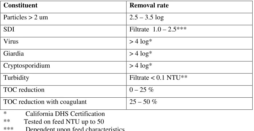
Table 1. Removal capability of capillary module
Constituent Removal rate
Particles > 2 um 2.5 – 3.5 log
SDI Filtrate 1.0 – 2.5***
Virus > 4 log*
Giardia > 4 log*
Cryptosporidium > 4 log*
Turbidity Filtrate < 0.1 NTU**
TOC reduction 0 – 25 %
TOC reduction with coagulant 25 – 50 % * California DHS Certification
** Tested on feed NTU up to 50
*** Dependent upon feed characteristics
reversed to remove particulate matter (backwash). The representative removal capability of the capillary module is summarized in Table 1. Membrane and process specifications for the HYDRAcap module is provided in Table 2.
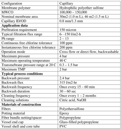
Table 2. Membrane and process parameters
Configuration Capillary
Membrane polymer Hydrophilic polyether sulfone
MWCO 100,000 – 150,000
Nominal membrane area 30m2 (1.0 m L), 46 m2 (1.5 m L)
Capillary ID/OD 0.8 mm/1.3 mm
Application data
Prefitration requirement 150 micron Typical filtration flux range 6- -150 l/m2-h
Ph range 2 – 13
Continuous free chlorine tolerance 100 ppm Instantaneous free chlorine tolerance 200 ppm
Operation mode Cross flow or direct flow, backwashable
Maximum pressure 4 bar
Maximum operating temperature 40 C
Transmebrane pressure range at 20 C 0.3 – 1.5 bar
Maximum TMP 2 bar
Typical process conditions
Backwash pressure 2.4 bar
Backwash flux 315 l/m2-hr
Backwash frequency Once every 15 – 60 min
Backwash duration 30 – 60 sec
Cleaning frequency Once every 1 – 2 months Cleaning solutions Citric acid, NaOH
Materials of construction
Fibers Polyethersulfone
Potting material Epoxy
Fiber bundle netting/spacer Polypropylene
Vessel end cap Glass-filled polypropylene Vessel shell and core tube PVC
Filter backwash water recovery.
processing surface water for potable applications. The backwash water may contain high concentrations of bacteria, giardia cysts and cryptosporidium oocysts. Conventional water treatment technology does not provide consistent removal level of pathogens. Membrane processes such as capillary ultrafiltration and microfiltration are more reliable in removing all suspended matter, including colloidal particles and pathogens. The capillary membrane provides a definite separation barrier, the integrity of which can be conveniently tested. However, even after the sedimentation step, the backwash stream still contains a high concentration of suspended solids (about 10 mg/l) that can easily plug the regular capillary bore of 0.8 mm ID. Therefore, for the backwash water recovery application a larger ID diameter fiber is required. Even with larger diameter fibers the process parameters have to be optimized to prevent solids accumulation in the module.
Capillary element configuration for backwash recovery.
Field experience indicates that, for backwash water recovery applications, capillary fibers with larger ID then the conventional 0.8 mm are required to prevent bore plugging. A 50% larger ID of 1.2 mm is sufficient to prevent fiber blockage by suspended matter encountered in filter backwash effluent. Due to the larger capillary diameter the module contains only 5600 fibers, which provides 19 m2 of membrane area for a 1 m long shell. For comparison a module with regular (0.8 mm) fibers contains about 13,000 fibers and 30 m2 membrane area for a module of the same length. Except for the fiber diameter and total membrane area, the module with large diameter capillaries has the same configuration as the one with 0.8 ID mm fibers. The flow configuration is also inside out, feed flows inside the capillary bore. The advantage of inside out configuration is that the feed flow follows a straight path, eliminating stagnant areas and the possibility of accumulating solids inside the module.
Operating parameters
Results and discussion
Enclosed graph (Fig 5) show the Flux and TMP profile of a module with 1.2 mm ID fibers operating of five weeks (16th May to 21st June). System operational data were taken approximately every four hours. These values correspond to the instant just after backwash. Performance was very stable over this period, with a permeability around 240 L/m2.h.bar after backwash dropping to approximately 140 L/m2.h.bar just before backwash.
[image:5.595.65.510.504.657.2]An initial trial period with a module containing 0.8 mm fibers showed that it was not possible to maintain permeability without using a full chemical cleaning procedure every few cycles. It appeared that the backwash process was not capable of removing accumulated solids effectively from the inside of the fibers, resulting in a progressive loss of permeability in successive cycles.
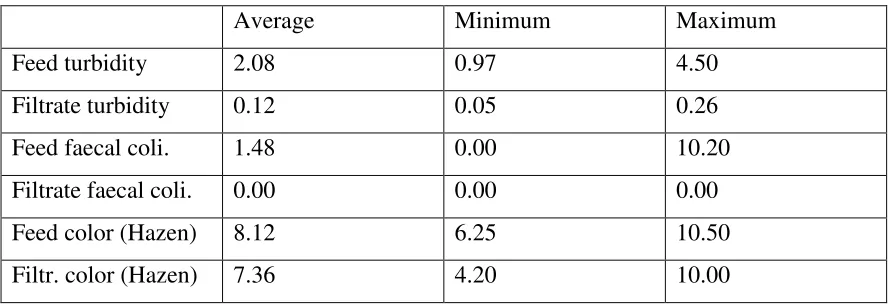
Table 3 shows a summary of feed and filtrate quality for the trial with the 1.2 mm fiber module. The results indicate very good reduction of turbidity and coliform bacteria. As can be expected no significant reduction of color was achieved. As the graph shows, occasionally the permeability declined, especially during the night and weekends, due to the fouling of the strainer. However, after manual cleaning of the strainer, the flux always returned to its original value, throughout the period of the trial. In addition, as the Fig 5 shows, the plant shut down on the 10th and 11th of June. This was also due to the high fouling of the strainer, which resulted in the permeate tank emptying. Strainer plugging was the result of the low permeate flow during operation, not producing the required amount of water to carry out the backwashes. Once again, after a proper cleaning of the strainer, the permeability returned to its normal value.
Table 3. Summary of feed and filtrate quality results.
Average Minimum Maximum
Feed turbidity 2.08 0.97 4.50
Filtrate turbidity 0.12 0.05 0.26
Feed faecal coli. 1.48 0.00 10.20
Filtrate faecal coli. 0.00 0.00 0.00
Feed color (Hazen) 8.12 6.25 10.50
Filtr. color (Hazen) 7.36 4.20 10.00
UF system design
plant will be designed to operate at a flux rate of 80 l/m2-hr with a 20 min operation sequence, between backwashing.
Cost.
The ultrafiltration system for reclamation of filter media backwash effluent will be more expensive than a UF system designed for the treatment of surface water. The higher cost is a result of operating the capillary membranes at a lower flux rate: 80 l/m2-hr as compared to 100 l/m3-hr. Also the membrane elements used for backwash recovery have about 63% of the membrane area of the regular elements. Therefore, for a given filtrate capacity, the backwash recovery system will consist of approximately twice the number of membrane elements than the one used for surface water treatment. Accordingly, the equipment cost and the operating cost of backwash recovery equipment will be higher. Using as a reference the published results of tender for a 20,000 m3/day capillary unit for treating surface water, the equipment cost of backwash recovery system is estimated to be about $200 /m3-day. The water cost components are listed in Table 4.
Table 4. Estimated cost components for backwash recovery system
Equipment cost, $/m3-d 200.0
Capital cost @ 6% interest rate, $/m3 0.040
Power, $/m3 0.007
Chemicals, $/m3 0.006
Membrane replacement, $/m3 0.034
Total water cost, $/m3 0.087
Conclusions
For the application of capillary filtration of the effluent from the thickener, use of fibers with 0.8 mm ID is not recommended due to the low backwash efficiency.
However, performance of the module with 1.2 mm ID fibers on the decantate from the thickener was excellent with a stable TMP of 0.35 - 0.40 bar at a flux of 80-100 L/h.m2 .
Backwash volumes were 7-8% of forward flow, and the recovery of the plant was close to 90%, including forward flush.
Filtrate quality was excellent (see Table 3).
For a full-scale plant design, the plant sizing would be based on 80 L/h.m2, with a 20
minutes run time between backflushing.
Disinfection with 10 ppm NaOCl is required 4 times a day.