A New Image Steganographic Approach for Secure Communication
Based on LSB Replacement Method
Khalid A. Darabkh
1, Iyad F. Jafar
1, Raed T. Al-Zubi
2, Mohammed Hawa
2The University of Jordan,
1 Computer Engineering Department, 2 Electrical Engineering Department,
Amman, 11942, Jordan
e-mail: [email protected], [email protected], [email protected], [email protected]
http://dx.doi.org/10.5755/j01.itc.44.3.8949
Abstract. With the development of internet technologies and communication services, message transmissions over the internet still have to face all kinds of security problems. Hence, how to protect secret messages during transmission becomes a challenging issue for most of current researchers. It is worth mentioning that many applications in computer science and other related fields rely on steganography and watermarking techniques to ensure information safety during communication. Unlike cryptography that focuses on scrambling the secret message so that it cannot be understood, the main objective of steganography and watermarking is to communicate securely in such a way that the hidden data are not visible to the observer. In other words, it seeks for the imperceptibility of stego-images quality to an unintended party through embedding efficiently the secret message in a digital media such as image, video, or audio. In this paper, we propose a new steganographic method to embed the secret data inside a cover image based on least-significant-bit (LSB) replacement method. The embedding process predominantly concentrates on distributing the secret message inside one share of a color image to appear like a 3D geometric shape that is constructed according to well-analyzed geometric equations. The dimensions of the geometric shape are determined pursuant to the size of secret message. Data distribution process makes our method to be of a great interest as of being so difficult for the hackers or intruders to reconstruct the shape from stego-images, thereby the security is improved. Furthermore, we compare the performance of our approach with two other relevant approaches in terms of peak signal-to-noise ratio (PSNR) and payload. The contribution of our approach was immensely impressive.
Keywords: Steganography, watermarking; data hiding; cover image; stego-image (watermarked data); geometric shape; least-significant-bit (LSB); security; imperceptibility; payload.
1. Introduction
Due to the fast growth of internet applications especially over wireless networks, digitized data become very prevailing bearing in mind that wireless networks have many drawbacks out of which low bandwidth, high bit error rate, and insecure links [1-6]. Hence, data to be transmitted may be vulnerable to interception as well. As indicators of its importance, intruders may not only reveal transmitted data to others, but also modify them to give a false idea of an individual or organization or even use it to launch attacks. Owing to the easiness of digital duplication and tampering, data security becomes a challenging matter for most of researchers nowadays. One of great interest solutions is the use of information hiding which encompasses many sub-disciplines, among them steganography and watermarking [7-12].
1.1. Steganography and watermarking
Watermarking does not verbatim sight to keep the existence of the information secret in order to repel attention of the potential attackers, but rather it aims at making the data imperceptible. It is noteworthy to mention that watermarking is closely related to steganography, but with slight differences described as follows [9-10]: steganography has reference to covert point-to-point communication between two parties, thus, requiring limited robustness. As far as the watermarking is concerned, it has relevance to the cover itself in which the data will be kept imperceptible to parties who know the existence of the hidden data and have an interest in knowing and removing them. In a few words, watermarking has an accessory notion of resilience against hacking trials. Additionally, secret data are inseparable from the cover in which they are embedded. To show its relevance to reality, many applications use watermarking, including copyright protection, content authentication, transaction tracking, and broadcast monitoring [22-23].
1.2. Digital watermarking: Classification, evaluation, and related work
As far as the watermarking techniques are concerned, they can be classified into six different categories in accordance with the following [24-26]: robustness, reversibility, scope, symmetry, blindness, and domain. In robustness category and according to their resistance to natural noise and artificial modifi-cations (attacks), the watermarking algorithms can be grouped as robust, semi-fragile, and fragile. However, the watermarking techniques are considered to be reversible if they are capable of converting the water-marked data into their original form after extraction. Otherwise, they are irreversible. As the selected data (pixels or signals) of the cover media are often changed immutably, current watermarking techniques are considered irreversible. Referring to the scope category, if the watermarking technique allows only authorized users to recover the watermark, then it is considered private. Otherwise, it is public bearing in mind that most researchers have reported the superiority of private watermarking techniques in the dimension of robustness. Touching on symmetry category, a watermarking algorithm is named as asymmetric if the detection/extraction process requires using different parameters than those used in the embedding process. Apart from that, if the same set of parameters is necessitated, then it is called symmetric. Due to security reasons, researchers have paid their attentions on asymmetric watermarking algorithms. On the category of blindness, a watermarking algo-rithm is called non-blind if the original media is entailed to be available at the time of detection or extraction. By contrast, it is considered blind if the original media required being present. As of being unsuitable for many practical applications, current researches focus on blind watermarking techniques instead. It deserves mentioning that there are
semi-blind watermarking algorithms which do not require the original media to be completely present at extraction time, but rather some of its features.
Apropos of domain category, the watermarking algorithms can be performed utilizing three different domains [25-26]: frequency, spatial, and quantization. In frequency domain, the raw data (pixels) of the original host image are transformed firstly into frequencies using discrete cosine transform (DCT), discrete wavelet transform (DWT), or other kinds of transforms. To achieve data hiding, these frequencies are altered conforming to the watermark bits. Thereafter, the inverse transform is performed and a watermarked image is consequently brought into being. In spatial domain, the raw data of the host image are modified on the spot according to the watermark bits [27]. In quantization domain, which is based on vector quantization (VQ) [28], the pixels of the host image are quantified using predefined code vectors. Afterwards, the indices generated are altered in consonance with the watermark bits. The watermark bits are reassembled according to a certain recovery process that depends on those adjusted indices. By doing so, the traditional vector quantization systems are significantly improved. It is noteworthy to mention that among these domains, the watermarking techniques using spatial domain are most advantageous as far as the computational time, visual quality, and easy implementation are concerned [25-26]. On the other hand, when it comes to robustness, the frequency-based techniques are more favorable against various attacks or noise affection [25].
As a matter of fact, there are many watermarking techniques proposed in the spatial domain [29-39]. Among these implemented watermarking techniques, the following are some of interesting and relevant schemes: Pixel-value differencing (PVD) and PVD cascaded with least-significant-bit (LSB). In PVD approach [29], the cover image is simply portioned into non-overlapping two-pixel blocks. The difference between each two consecutive pixels of any block determines how much data can be embedded. In other words, small and large differences denote for working at pixels located in smooth and edge image regions and tolerate small and large changes in their values, respectively. The authors proposed a range table that contains all possible differences in the whole image region in which the selection relies on the sensitivity of human vision to gray value variations. The main goal of doing this is to keep the resulting stego-images unnoticeable. For interested readers, further details can be found in [29]. In [30], both PVD and LSB substitution method have been cascaded for the reason of obtaining more hiding capacity. After embedding using PVD approach, the idea proposed in [30] simply encompasses embedding using LSB method in the first pixel of each pixel pair (block). The distortion, made by LSB method, is then adjusted through modifying the second pixel of that block in a way that the difference between pixels, calculated from PDV approach, is kept.
1.3. Our methodology
Taking advantage of LSB scheme, we propose, in this paper, a very efficient watermarking approach. In this approach, the watermark is constructed on the form of a geometric shape that appears like a 3D house in which its dimensions are variable and depend on the size of secret data. The media used is colored images. To the best of our knowledge, this is a brand new idea and no prior work is similar to ours. However, the house geometric shape is divided into four areas where all are included in the embedding process as will be discussed shortly. For comparison purposes, the red share is used each time to embed the data according to the pixel area bearing into consideration that our approach is flexible to accept incorporating all shares in the embedding process. It is unforgettable to state that our approach fulfills the security watermarking evaluation objective mentioned earlier. In other words, the house geometric shape makes the emission of the attacker harder due to the endless effort needed to find the equations of the house required to find the watermark. The secret bits per pixel (embedding depth) are chosen up to five bits and this is to conserve the transparency and capacity evaluation objectives. Apart from that, our scheme falls within spatial domain category. Hence, the payload (hiding capacity) is considered to be high compared to those schemes proposed in either transform or quantization domains. Due to changing only one share byte of the pixel at a time and having
the size of the house variable pursuant to the size of watermark, the imperceptibility (i.e., the closeness of visual quality between the original and watermarked images) is achieved. As there is no need, in our watermarking approach, to convert the image into different domains (frequency/quantization) or different spaces (e.g., gray-scale) and there is no heavy computational operations such as multiplication and division required on pixels, the computational time is low. Furthermore, since there is no need for the original image or its features to be present in the exaction phase, our watermarking technique is blind. Additionally, our watermarking technique is a standalone since it is not combined with another transform- or quantization-based watermarking algorithm which makes it easier to improve and modify. Preliminary results of our proposed work have been presented in [40].
The remainder of the paper is organized as follows. The proposed watermarking approach is elucidated in Section 2 in which the embedding procedures for all areas have been extensively clarified. Experimental results along with observations and necessary discussions are presented in Section 3. The paper is summarized in Section 4.
2. Proposed Approach
2.1. The concept of geometric shape
The secret data are embedded in color images in the guise of a 3D geometric shape. The embedding occurs in the least significant bits of the red share. The size of this geometric shape is variable according to the secret data size and embedding depth which represents the number of secret bits that need to be inserted and is chosen to be five to maintain the imperceptibility and payload. In order to have a variable shape of the watermark inside a digital image, we should be aware of the following points:
1. Finding the number of pixels needed, which is equal to the ceiling of watermark size (in bits) divided by the embedding depth, 2. Finding the areas entailed to hide the
watermark where the overall area indicates the number of needed pixels found in point 1. As seen in Fig. 1, the variable shape is divided into four different areas where each area is calculated with respect to Area1 as follows: Area2 = 0.25 * Area1, Area3 = 0.25 * Area1, as well as Area4 = 0.125 * Area1. It is important to mention that the factors of
Figure 1. The geometric shape of proposed approach
2.2. The embedding procedure
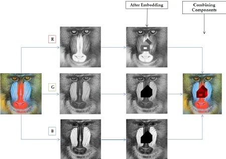
On account of being easily applied for gray-scale images and comparing its performance with other pertinent proposed watermarking algorithms, we consider in our work embedding in just one share of the image which is settled on red bearing in mind that inVolving all images shares may be better for enhancing the security objective. However, Fig. 2 describes the strides entailed to construct the geometric shape that professes to be the watermark. Interestingly, the pixels located in Area2 and Area4
will inVolve embedding in the semblance of a parallelogram. Similarly, the shapes of triangle and rectangle will be formed if the pixels are located in
Area3 and small and big windows of Area1,
respectively. To improve the security, we start embedding the secret data in the small window, and the rest will be resumed in the big window but in the opposite direction. It is good to stress on the point made to improve the imperceptibility that if the secret data are embedded in any pixel of the red share, then the same pixel at the corresponding positions of the other shares will not be affected (immutable). However, after embedding the secret data, the resulting shape will look like a 3D house as shown down in Fig. 2. However, the geometric shape is invisible in the watermarked image.
To fully understand how the embedding technique is specifically performed, it is important to know first about the distribution of pixels chosen. In our embedding technique, we consider any image as an array where each pixel location is represented by (i,j) where i and j refer to the column and row locations, respectively. In other words, the array index starts with the location (1,1) that represents the top left side as shown in Fig. 3. The row and column indices increase when moving downward and to the right direction of the image, respectively. However, the construction of the proposed geometric shape and embedding in it is illustrated in the following subsections.
Figure 3. The distribution of image pixels
Figure 4.Area1 dimensions
2.2.1. Embedding in Area1
The geometric shape is constructed in the middle of original image so that, when the shape is expanded according to the hidden data size, a large number of pixels will be used to hide the data. To guarantee dealing with integer operations, all proposed formulas, in Section 2, use the ceiling function. However, to embed the data inside Area1 which represents a
rectangle as shown in Fig. 4, we assume that
. Area Y
1
1 3
2 (1)
Consequently, the width X1 can be found as
. Area X
1
1 2 3
The point (Mid_x,Mid_y)is found as
. height _ age Im y _ Mid , width _ age Im x _ Mid
2 2
(2)
As shown in Fig. 4, W_X represents the width of small window and W_L is the width to the left of big window which is the same as W_R that deputizes for the width to the right of this window. Therefore,
L
W
_
is assumed to be. X L _ W
1
3
1 (3)
Hence,
W
_
X
can be found as. X X X _ W
1 1
3
2 (4)
It should be realized that
X
1 is considered as the major dimension of the proposed geometric shape. After using (2) and (3), it can be expressed in terms of only image width as follows
4 3 1 Mid_x W_R
X * Image_width. (5)
H_A indicates the height above the small window which is the same as H_B (the height below the small window). However, they are assumed to be
. Y B _ H A _ H
1
3
1 (6)
Consequently, the height of small window (H_Y) can be exhibited as
. Y Y Y _ H
1 1
3
Utilizing (3), (4) and (7), we can find that the top left point of Area1 (Tlp_area1_x, Tlp_ area1_y) can be
manifested as . Y y _ Mid y _ area _ Tlp , X X x _ Mid x _ area _ Tlp
1 1 1 1
1
3 1 3
1 (8)
Using (4), the starting point of the window (Sp_w_x ,Sp_w_y) can be found as
. y _ Mid y _ w _ Sp , X X x _ Mid x _ w _ Sp
1 1
3
2 (9)
Wielding (4), (7), and (9), the end point of the window (Ep_w_x ,Ep_w_y) can be expressed as
. Y Y y _ Mid y _ w _ Ep , x _ Mid x _ w _ Ep
1 1
3
2 (10)
It is worth mentioning that if the dimensions of the image are given, then the middle point will be easily found which in turn facilitates finding all aforementioned variables. However, the head of secret data is embedded in the small window region while the rest is embedded in the antithesis direction of big window region. In fact, this is done to improve the security. However, since Area1 shares Area3 with the
same width and Area2 with the same height, then
X
1and
Y
1 should appear in the discussions of Area3 andArea2, respectively.
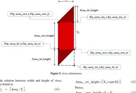
2.2.2. Embedding in Area2
Area2 is divided into three shapes: a rectangle and
two triangles as detailed in Fig. 5. The lower and upper triangles are mirrored and completely identical. To recognize the embedding process in this area, equations (11)-(18) are analytically derived.
Figure 5.Area2 dimensions
The relation between width and height of Area2
can be found as
Area /Y
.X2 2 2 (11)
As mentioned earlier, Area1 and Area2 have the
same height. Hence, we find Y2=Y1.Area2 is drawn
using isometric angle equal to 45° (as shown in Fig. 5). To find the height of triangles and rectangle, we find
X tan( )
. height_ tri _
Area2 2 45 (12)
Hence, . X Y height _ rect _
Area2 2 2 (13)
The top left point of rectangle
x
rect
area
Tlp
_
_
_
(
2 ,Tlp
_
area
2_
rect
_
y
)
canbe found when referring to (8) as
. Y y _ Mid y _ rect _ area _ Tlp , X x _ Mid x _ rect _ area _ Tlp
1 2 1
2
3 1 3
The end point of rectangle (Ep_area2_rect_x,
) _ _
_area2 rect y
Ep can be expressed after
utilizing (13) and (14) as
. X Y Y y _ Mid y _ rect _ area _ Ep , X X x _ Mid x _ rect _ area _
Ep 2 1 2 2 1 2 2
3 1 3 1 (15)
After utilizing (14) and (15), the top left point of lower triangle (Tlp_area2_tri_x ,
) _ _
_area2 tri y
Tlp is expressed as follows
. X Y Y y _ Mid y _ tri _ area _ Tlp , X x _ Mid x _ tri _ area _
Tlp 2 1 2 1 2 2
3 1 3 1 (16)
Refering to (12), (15) and (16), the end point of lower triangle (Ep_area2_tri_x,
) _ _
_area2 tri y
Ep can be found as
. Y Y y _ Mid y _ tri _ area _ Ep , X X x _ Mid x _ tri _ area _
Ep 2 1 2 2 1 2
3 1 3 1 (17)
Using (14), the end point of upper triangle ( x
tri area
Ep_ 2_ 2_ ,Ep_area2_tri2_y) is found as
. Y y _ Mid y _ tri _ area _ Ep , X X x _ Mid x _ tri _ area _ Ep
1 2 2 2 1
2 2 3 1 3 1 (18)
2.2.3. Embedding in Area3
Area3 is shown in Fig. 6 which constitutes an
equilateral triangle where its base is shared with Area1
(i.e., X3= X1). To elucidate how the embedding in this
area occurs, formulas (19)-(22) are provided.
Figure 6.Area3 dimensions
The height of triangle is found as
). tan( X height _ tri _
Area 45
2 1
3 (19)
Referring to (8), the leftmost point (Lp_area3_x,Lp_ area3_y) can be found as
. Y y _ Mid y _ Lp_area , X X x _ Mid x _
Lp_area3 3
1 1 1
3 1 3
1 (20)
Using (8) and (14), the rightmost point (Rp_ area3_x,Rp_ area3_y) can be extracted as
. Y y _ Mid y _ Rp_area , X x _ Mid x _
Rp_area3 3
1 1
3 1 3
1 (21)
. X Y y _ Mid y _ Tp_area , X X x _ Mid x _
Tp_area3 3
2 3 1 3 1 2 1 1 1 1
1
(22)
2.2.4. Embedding in Area4
Area4 is depicted in Fig. 7 which includes a
rectangle rotated by 45° from the x-axis in which its height and width are shared with Area3 and the upper
triangle of Area2, respectively. The equations (23)-(27)
are formulated to make the embedding in this area readable and understandable.
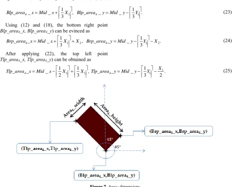
Referring to (14), the bottom left point of Area4
(Blp_area4_x, Blp_area4_y) can be extracted as
. Y y _ Mid y _ Blp_area , X x _ Mid x _
Blp_area4 4
1 1
3 1 3
1 (23)
Using (12) and (18), the bottom right point (Blp_area4_x, Blp_area4_y) can be evinced as
. X Y y _ Mid _y Brp_area , X X x _ Mid _x
Brp_area4 1 2 4 1 2
3 1 3 1 (24)
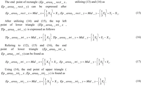
After applying (22), the top left point (Tlp_area4_x, Tlp_area4_y) can be obtained as
. X Y y _ Mid _y Tlp_area , X X x _ Mid _x
Tlp_area4 4
2 3 1 3 1 2 1 1 1 1
1
(25)
Figure 7. Area4 dimensions
Using (23) and (25), we can find that
. X _height Area4 2 1 (26)
and Area4_widthX2 2. (27)
As formerly mentioned when finding the number of pixels required to embed the selected secret data, we used the
⌈𝑐𝑖𝑒𝑙𝑖𝑛𝑔⌉
which may result in having a fraction number. Hence, if that is the case, the remaining data bits are embedded in the last pixel of the chosen image. Apart from that, a group of pixels is reserved, in our work, to embed the control information needed for reconstructing the geometric shape at the receiver side. These data include the watermarked bytes, embedding depth, as well as the size of remaining data bits.It is noteworthy to mention that the process of recovering the embedded data from stego-images simply depends on the dimensions of each area as illustrated in each corresponding segment construction mentioned above.
3. Results and Discussions
the literature, namely PVD and PVD cascaded with LSB, we consider peak signal-to-noise ratio (PSNR) and payload performance metrics. It deserves disclosing that for the reason of having a fair comparison, we implement the former approaches on the red share of color images precisely as described. However, PSNR is a very popular function for
evaluating the imperceptibility or visual quality of the watermarked result [41-44]. The PSNR is computed after finding the mean square error (MSE) which is found as [45-47]
, )] , ( ) , ( [(
1 1
0 1
0
2
m
i n j
j i W j i C mn
MSE (28)
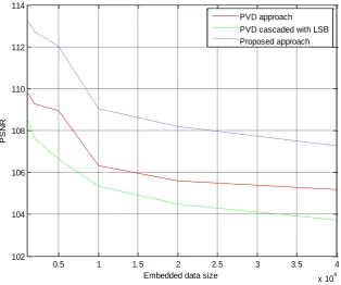
Figure 8. PSNR versus watermark size (in bytes) for different watermarking methods using cover image “Couple”
Figure 9. PSNR versus watermark size (in bytes) for different watermarking methods using cover image “Baboon”
0.5 1 1.5 2 2.5 3 3.5 4
x 104 104
106 108 110 112 114 116 118
Embedded data size
P
S
N
R
PVD approach PVD cascaded with LSB Proposed approach
0.5 1 1.5 2 2.5 3 3.5 4
x 104 102
104 106 108 110 112 114
Embedded data size
P
S
N
R
where C (i ,j ) represents the cover (original) image and W(i,j) is the watermarked image where both have a size of (n×m). Thus, the PSNR is defined as [29-30, 48]
, 10
2
10
log
MSE MAX
PSNR (29)
where MAX indicates the maximum possible value for image pixels. For monochrome (grayscale) images, which are presented in an 8-bit format, MAX = 255. In our work, we consider working with color images. Hence, the PSNR formula requires multiplying the denominator of (29) by a factor of 3.
The payload represents the hiding capacity of a watermarking technique and differs from a watermarking technique to another. However, in our proposed watermarking scheme and in light of our previous derived equations, the capacity can be numerically approximated per one image share as follows:
.
8
Depth
Embedding
*
12
13
Capacity
2 1
X
(30)Fig. 8 shows the results of PSNR performance metric versus different watermark lengths when experimenting (simulating) our proposed approach and two other popular approaches, that is to say, PVD [29] and PVD cascaded with LSB [30]. The host image used is Couple. It is worth stating that higher obtained values of PSNR indicate having better results. In other words, as the difference between original and stego-image gets closer and closer, the PSNR gets higher and higher. As seen in this figure, the PSNR values decrease as the watermark size increases. This is to be expected since the number of characters embedded increases. Unlike other proposed approaches, our proposed approach achieves higher values of PSNR for all described watermark lengths. With reference to what are mentioned about PVD and PVD cascaded with LSB in Section 1, it is noteworthy to realize and conclude that these approaches may affect the stego-images more than our approach. To show its consistent contribution over other standard test images, Fig. 9 shows the PSNR results for a different cover image (i.e., Baboon). It is worth noting that the PSNR values for PVD are higher than those for PVD cascaded with LSB and these completely comply with what are reported in [30]. To prove the quality of our stego-images visually, Fig. 10 unveils a group of cover and watermarked images after conducting experiments with our proposed approach. The high sight quality is undeniable and very magnificent.
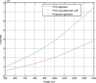
Figs. 11 and 12 expound the hiding capacity (in bytes) versus various image sizes using different watermarking approaches for the cover images Couple and Baboon, respectively. The image size shown in the x-axis typifies just one dimension of an image since all images chosen are resized in which
each has the same width and height. The increase in the payload as the image size increases is noticed for all employed approaches. In fact, this is due to having more space to hide data. Moreover, the contribution of PVD cascaded with LSB approach over PVD approach is distinguished and catching the sight. Actually, this agrees fairly with what are concluded in [29] bearing in mind that this approach works at the expense of PSNR as seen in Figs. 8 and 9. As far as our proposed approach is concerned, its contribution is almost the same as PVD cascaded with LSB approach and may get improved as the image size increases more and more. Interestingly, our proposed approach does not work against the PSNR values but rather it accomplishes the best results as observed in Figs. 8 and 9. The approximate derivation for the payload of our proposed approach is found in equation (30). In a nutshell, our proposed approach has significant contributions over both PVD and PVD cascaded with LSB approaches with respect to visual quality and hiding capacity.
4. Conclusion
(a) (b)
Figure 11. Payload versus different images sizes for different watermarking methods using cover image “Couple”
Figure 12. Payload versus different images sizes for different watermarking methods using cover image “Baboon”
Acknowledgment
The authors would like to thank the students who have participated in developing the system and making this work possible, particularly, Hala Ismail, Dana Hijaz, and Rawan Amayreh.
References
[1] K. A. Darabkh, R. Aygun. Improving UDP Performance Using Intermediate QoD-aware Hop System for Wired/Wireless Multimedia Communi-cation Systems. International Journal of Network Management, 2011, Vol. 21, No. 5, 432–454.
500 600 700 800 900 1000 1100 1200 1300 1400
0 1 2 3 4 5 6 7
8x 10
5
Image size
P
a
y
lo
a
d
PVD approach
PVD cascaded with LSB Proposed approach
500 600 700 800 900 1000 1100 1200 1300 1400
0 1 2 3 4 5 6 7
8x 10
5
Image size
P
a
y
lo
a
d
PVD approach
[2] K. A. Darabkh, R. S. Aygün. TCP Traffic Control Evaluation and Reduction over Wireless Networks Using Parallel Sequential Decoding Mechanism.
EURASIP Journal on Wireless Communications and Networking, 2007, Vol. 2007, Article ID 52492, 1-16. [3] K. A. Darabkh. Queuing Analysis and Simulation of
Wireless Access and End Point Systems using Fano Decoding. Journal of Communications, 2010, Vol. 5, No. 7, 551-561.
[4] K. A. Darabkh. Evaluation of Channel Adaptive Access Point System with Fano Decoding.
International Journal of Computer Mathematics, 2011, Vol. 88, No. 5, 916–937.
[5] K. A. Darabkh. Fast and Upper Bounded Fano Decoding Algorithm: Queuing Analysis. Transactions on Emerging Telecommunications Technologies, 2015, DOI: 10.1002/ett.2929.
[6] K. A. Darabkh, B. Abu-Jaradeh, I. Jafar. Incor-porating Automatic Repeat Request and Thresholds with Variable Complexity Decoding Algorithms over Wireless Networks: Queuing Analysis. IET Communications, 2011, Vol. 5, No. 10, 1377–1393. [7] S. Wang, D. Zheng, J. Zhao, W. J. Tam,
F. Speranza. Adaptive Watermarking and Tree Structure Based Image Quality Estimation. IEEE Transactions on Multimedia, 2014, Vol. 16, No. 2, 311-325.
[8] K. Zebbiche, F. Khelifi. Efficient wavelet-based per-ceptual watermark masking for robust fingerprint image watermarking. IET Image Processing, 2014, Vol. 8, No. 1, 23-32.
[9] Y. Zhou, W. W. Y. Ng. A study of influence between digital watermarking and steganography. In:
Proceedings of the 2013 International Conference on Wavelet Analysis and Pattern Recognition, Tianjin, July 2013, pp. 49-55.
[10] C. Whitelam, N. Osia, T. Bourlai. Securing multi-modal biometric data through watermarking and steganography. In: Proceedings of 2013 IEEE International Conference on Technologies for Homeland Security (HST), Waltham, MA, USA, November 2013, pp. 61-66.
[11] B. E. Carvajal-Gamez, F. J. Gallegos-Funes, V.I. Ponomaryov, R. Cruz-Santiago. A new stegano-graphic method for RGB color images using estimation of variance field in the wavelet domain. In: Procee-dings of 2013 International Kharkov Symposium on Physics and Engineering of Microwaves, Millimeter and Submillimeter Waves (MSMW), Kharkov,Ukraine,
November 2013, pp. 626-628.
[12] K. A. Darabkh. Imperceptible and Robust DWT-SVD-Based Digital Audio Watermarking Algorithm.
Journal of Software Engineering and Applications, 2014, Vol. 7, No. 10, 859-871.
[13]
M. Li, M. K. Kulhandjian, D. A. Pados, S. N. Batalama, M. J. Medley. Extracting Spread-Spectrum Hidden Data From Digital Media. IEEE Transactions onInformation Forensics and Security, 2013, Vol. 8, No. 7, 1201-1210.[14] S. Mukhopadhyay, H. Leung. Multi Image Encryp-tion and Steganography Based on SynchronizaEncryp-tion of Chaotic Lasers. In: Proceedings of 2013 IEEE International Conference on Systems, Man, and Cybernetics (SMC), Manchester, October 2013, pp. 4403-4408.
[15] D. Artz. Digital steganography: hiding data within data. IEEE Internet Computing, 2001, Vol. 5, No. 3,75-80.
[16] J. Fridrich, J. Kodovsky. Rich Models for Steganalysis of Digital Images. IEEE Transactions on Information Forensics and Security, 2012, Vol. 7, No. 3, 868-882.
[17] M. A. F. Al-Husainy. Image steganography by mapping pixels to letters. Journal of Computer Science, 2009, Vol. 5, No. 1, 33-38.
[18] M. Kharrazi, H. T. Sencar, N. Memon. Performance study of common image steganography and steganalysis techniques. Journal of Electronic Imaging, 2006, Vol. 15, No. 4, Article No. 041104. [19] N. A. Kofahi, T. Al-Somani, K. Al-Zamil.
Perfor-mance study of some symmetric block cipher algorithms under Linux operating system. Journal of Discrete Mathematical Sciences & Cryptography, 2004, Vol. 7, No. 3, 359-370.
[20] S. Li, X. Zheng. Cryptanalysis of a chaotic image encryption method. In: Proceedings of ISCAS 2002 IEEE International Symposium on Circuits and Systems (ISCAS 2002), 2002, Vol. 2, Scottsdale, Arizona, 708-711.
[21] N. Provos, P. Honeyman. Hide and seek: an introduction to steganography. IEEE Security & Privacy, Vol. 1, No. 3, pp. 32-44, May-June 2003. [22] P. Bas, T. Furon. A New Measure of Watermarking
Security: The Effective Key Length. IEEE Transactions on Information Forensics and Security,
2013, Vol. 8, No. 8, 1306-1317.
[23] T. Bianchi, A. Piva. Secure Watermarking for Multimedia Content Protection: A Review of its Benefits and Open Issues. IEEE Signal Processing Magazine, 2013, Vol. 30, No. 2, 87-96.
[24] I. Jafar, S. Hiary, K. A. Darabkh. An Improved Reversible Data Hiding Algorithm Based on Modification of Prediction Errors. In: Proceedings of the 2014 6th International Conference on Digital
Image Processing (ICDIP 2014), Athens, Greece, April 2014, pp. 91591U-91591U-6.
[25] F. Y. Shih. Digital watermarking and steganography: fundamentals and techniques. CRC Press, 2008. [26] F.-H. Wang, J.-S. Pan, L. C. Jain. Innovations in
Digital Watermarking Techniques. Studies in Computational Intelligence, 2009, Vol. 232, Springer-Verlag, Berlin.
[27] W. N. Cheung. Digital image watermarking in spatial and transform domains. In: Proceedings of IEEE TENCON 2000, Kuala Lumpur, 2000, Vol. 3, pp. 374378.
[28] A. Gersho, R. M. Gray. Vector Quantization and Signal Compression. Springer, Norwel, Massachusetts, USA, 1992.
[29] D.-C. Wu, W.-H. Tsai. A steganographic method for images by pixel-value differencing. Pattern Recogni-tion Letters, 2003, Vol. 24, No. 9–10, 1613-1626. [30] J. K. Mandal, D. Das. A Novel Invisible
Water-marking Based on Cascaded PVD Integrated LSB Technique. In: Proceedings of the 17th International
[31] M. Younes, A. Jantan. A New Steganography Approach for Images Encryption Exchange by Using the Least Significant Bit Insertion. International Journal of Computer Science and Network Security, 2008, Vol. 8, No. 6, 247-257.
[32] S.-H. Yen, C.-J. Wang. SVM Based Watermarking Technique. Tamkang Journal of Science and Engineering, 2006, Vol. 9, No. 2, 141-150.
[33] J. A. Hussein. Spatial Domain Watermarking Scheme for Colored Images Based on Log-average Luminance.
Journal of Computing, 2010, Vol. 2, No. 1, 100-103. [34] R. Kaur, M. Kaur, R. Malhotra. A New Efficient
Approach towards Steganography. International Journal of Computer Science and Information Techno-logies, 2010, Vol. 2, No. 2, 673-676.
[35] Y. Naderahmadian, S. Hosseini-Khayat. Fast and robust watermarking in still images based on QR decomposition. Multimedia Tools and Applications,
2014, Vol. 72, No. 3, 2597-2618.
[36] W. Bender, D. Gruhl, N. Morimoto, A. Lu. Techniques for data hiding. IBM Systems Journal, 1996, Vol. 35, No. 3–4, 313–336.
[37] Y. K. Lee, L. H. Chen. High capacity image steganographic model. IEE Proceedings on Vision, Image and Signal Processing, 2000, Vol. 147, No. 3, 288-294.
[38] R.-Z. Wang, C.-F. Lin, J.-C. Lin. Image hiding by optimal LSB substitution and genetic algorithm.
Pattern Recognition, 2001, Vol. 34, No. 3, 671–683. [39] C.-C. Chang, J.-Y. Hsiao, C.-S. Chan. Finding
optimal least-significant-bit substitution in image hiding by dynamic programming strategy. Pattern Recognition, 2003, Vol. 36, No. 7, pp. 1583-1595. [40] K. A. Darabkh, I. F. Jafar, R. T. Al-Zubi, M. Hawa.
An improved Image Least Significant Bit Replacement Method. In: Proceedings of 37th IEEE International
Convention on Information and Communication Tech-nology, Electronics and Microelectronics (MIPRO 2014), Opatija, Croatia, May 2014, pp. 1182-1186.
[41] I. F. Jafar, R. A. AlNa’mneh, K. A. Darabkh. Efficient Improvements on the BDND Filtering Algorithm for the Removal of High-Density Impulse Noise. IEEE Transactions of Image Processing, 2013, Vol. 22, No. 3, 1223-1232.
[42] I. Jafar, K. A. Darabkh, G. Al-Sukkar. A Rule-based Fuzzy Inference System for Adaptive Image Contrast Enhancement. The Computer Journal, 2012, Vol. 55, No. 9, 1041-1057.
[43] I. Jafar, K. A. Darabkh. Image Contrast Enhancement Based on Equalization of Edge Histograms. IAENG International Journal of Computer Science, 2011, Vol. 38, No. 3, 192-204. [44] I. Jafar, K. A. Darabkh. A Modified
Unsharp-masking Technique for Image Contrast Enhancement. In: Proceedings of IEEE/SSD’11 Multi-conference on Systems, Signals, and Devices, Sousse, Tunisia, May 2014, pp. 1-6.
[45] K. A. Darabkh, A. M. Awad, A. F. Khalifeh. New Video Discarding Policies for Improving UDP Performance over Wired/Wireless Networks.
International Journal of Network Management, 2015, Vol. 25, No. 3, 181-202.
[46] K. A. Darabkh, A. M. Awad, A. F. Khalifeh. Efficient PFD-Based Networking and Buffering Models for Improving Video Quality over Congested Links. Wireless Personal Communications, 2014, Vol. 79, No. 1, 293-320.
[47] K. A. Darabkh, A. M. Awad, A. F. Khalifeh. Intelligent and Selective Video Frames Discarding Policies for Wireless Networks. In: Proceedings of the 2013 IEEE International Symposium on Multimedia (ISM 2013), Anaheim, California, USA, December 2013, pp. 297-300.
[48] Y. Yalman, İ. Ertürk. A New Color Image Quality Measure based on YUV Transformation and PSNR for Human Vision System. Turkish Journal of Electrical Engineering & Computer Sciences, 2013, Vol. 21, No. 2, 603-612.