INTRODUCTION
A mechanical jack is a device which lifts heavy equipment and vehicles so that mainte-nance can be carried out underneath. The most common reason for using a car jacks is a change of tire, but it can also be used for various other repairs [1]. Currently, there are a lot of different car jacks designs available at the market. They can be divided into two main groups: mechanical-based (thread spindle) and hydraulic-mechanical-based. The most important characteristics of every car jack are lift height, load capacity, and static stability during lifting. Stability is especially important for safe lifting. During the design process, for better stability, it is important to seek advice from the people with experience and from technical staff. Stability is mostly defined by the shape and de-sign of the car jack.
Depending on the type of the vehicle and per-sonal requirements from the vehicle owner, there are a lot of different criteria for choosing the right car jack. Basically, every type of car jack is good enough for tire changing. Among the car jacks, there is a lot of differences in the working prin-ciples, mode of use, lifting height, load capacity and price. The goal of this paper was to create a parametric CAD model of a car jack. Then, this parametric CAD model was used for numerical
Development of Parametric CAD Model and Structural Analysis
of the Car Jack
Nedim Pervan
1*, Adis J. Muminović
1, Adil Muminović
1, Muamer Delić
11 University of Sarajevo, Mechanical Engineering Faculty Sarajevo , Vilsonovo šetalište br. 9, Sarajevo, Bosnia
and Herzegovina
* Corresponding author’s e-mail: [email protected]
ABSTRACT
The purpose of a car jack is lifting the car and maintaining it at a certain height during different repairs. This
paper focuses on the design of car jack, which belongs to the basic equipment of cars. Cars jacks are used mainly for changing tires and small repairs of a car. The aim of this paper was to create a parametric CAD model of a car jack and carry out numerical structural analysis of the car jack using the created parametric CAD model. The development of the parametric CAD model and structural analysis was performed using the CATIA V5 system.
This paper describes the modern way of creating more complex mechanisms, which support quick modification
of its parameters, and thus the entire design. The whole model of the car jack was parametrized. The stresses
obtained by finite element method (FEM) analysis were confirmed with the analytical calculation in character -istic parts of the design, with some exceptions. At the end of the paper, an analysis of the obtained results was
performed, on the basis of which specified conclusions were made.
Keywords: car jack, parametric model, theoretical analysis, structural analysis
Volume 13, Issue 3, September 2019, pages 24–30
https://doi.org/10.12913/22998624/109791
Research Journal
Accepted: 2019.07.05Available online: 2019.07.16
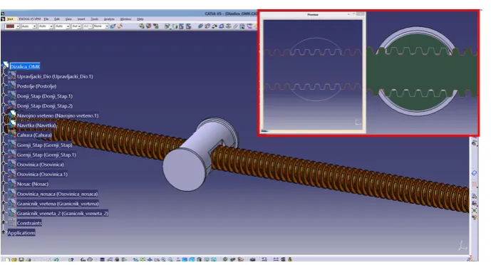
structural analysis using finite element method (FEM). For this research, the most common car jack variant was chosen (Figure 1).
A lot of different studies regarding thread spindle car jacks have been perfomed. As a result, numerous patents were filed [2, 5, 10, 17, 20].
DEVELOPMENT OF CAR JACK
PARAMETRIC 3D MODEL
The goal of developing a car jack paramet-ric 3D model is to obtain a functional 3D model which can be changed easily by editing some of the parameters. In the case of a car jack, it is im-portant to easily change position and shape of the car jack to simulate lifting of a car. This is pos-sible only if the model is fully parametric.
The term parametric design associated with parametric systems is defined as “a process of designing with parametric models in a virtual sur-rounding where geometrical and parameter varia-tion are natural” [18, 19].
Except parameters, for this type of 3D mod-eling and numerical analysis, it is important to use links to link all individual parts in functional assembly. Using links enables to automatically update all changes on individual parts in all as-semblies where that part is copied. In order to enable copying of individual parts, it is neces-sary to make them public. Before publishing parts, a designer must check the names of all parts, because two or more parts cannot have the same name. Links are especially important to show threads in real form.
The control part is main part of parametric controlled assembly model. Inside this part, there
is all information about the assembly, information like coordinate systems, parameters, sketches, planes, etc. Except basic parameters (lift height, length of beams, etc.) this control part has all pa-rameters for all other parts of assembly.
During the numerical structural analysis of the car jack, special focus needs to be placed on the thread spindle and thread nut. Threads need to be modeled as closely to the real one as pos-sible. Modeling of threads is not a problem; how-ever, establishing real connection between thread spindle and thread nut constitutes an issue. This connection can not be established using standard constrains, links needs to be used. Standard con-strains can not enable to move thread nut along the thread spindle.
Figure 2 shows a model of thread nut and thread spindle connection. It can be noticed that there is not any material penetration between thread nut and thread spindle. This will stay the same for any position of car jack.
THEORETICAL ANALYSIS OF CAR JACK
The design of the selected car jack (Figure 1) can be replaced with beam elements connect-ed in joints (Figure 3). Joints A and B are usconnect-ed for fix connection with the ground. This design is statically undefined case, but because the car jack is symmetric, all forces can be calculated analytically.
Because of a symmetric design, (left side is loaded same as right size) forces can be calculated:
𝑋𝑋𝐴𝐴= 𝑋𝑋𝐵𝐵 ; 𝑌𝑌𝐴𝐴= 𝑌𝑌𝐵𝐵 (1)
From static laws for points E, A and C, the forces in beams and thread spindle can be calculated:
𝑆𝑆1=2 sin 𝛽𝛽 =𝐹𝐹 sin 𝛽𝛽 𝑚𝑚𝑚𝑚 (2)
𝑆𝑆2=sin 𝛼𝛼 𝑌𝑌𝐴𝐴 (3)
𝐹𝐹𝑉𝑉= 𝑆𝑆2cos 𝛼𝛼 + 𝑆𝑆1cos 𝛽𝛽 (4)
where: F – force which represents full load on car jack,
m = 900 kg – load of the car jack in form of mass,
g = 9.81 m/s2 – gravitational acceleration.
The stresses in the rod of car jacks
Using known forces in beams, calculated ac-cording to equation 2 and 3, the dimensions of rods and thread spindle can be calculated. Rods have different cross section along their length, so dimensions need to be calculated in the critical cross section. The critical cross section is found on the upper rods where they are connected with shaft. The design of the upper rod and its cross section is shown in Figure 4.
The center of gravity for cross section shown on Figure 4b can be calculated using this equation:
yc=ΣAΣAiiyci=2(𝐴𝐴1𝑦𝑦𝑐𝑐12(𝐴𝐴1+ 𝐴𝐴+ 𝐴𝐴22𝑦𝑦𝑐𝑐2+ 𝐴𝐴+ 𝐴𝐴3) + 𝐴𝐴43𝑦𝑦𝑐𝑐4) + 𝐴𝐴4𝑦𝑦𝑐𝑐4 (5) The load force of thecar jack is transmitted from shaft to rods. The center of gravity of rod is not aligned with the center of gravity of shaft; hence, the rod is loaded with pressure which is not aligned with rod axis. Basically, the rod is loaded with combination of pressure and bending.
The pressure stress can be calculated using this equation:
𝜎𝜎𝑝𝑝=𝑆𝑆𝐴𝐴 =1 2(𝐴𝐴 𝑆𝑆1
1+ 𝐴𝐴2+ 𝐴𝐴3) + 𝐴𝐴4 (6)
Bending stress, in upper and lower fibers can be calculated using these equations:
𝜎𝜎𝑠𝑠−=𝑀𝑀𝐼𝐼𝑥𝑥
𝑥𝑥 𝑦𝑦𝑐𝑐 ; 𝜎𝜎𝑠𝑠+= 𝜎𝜎𝑠𝑠− ℎ − 𝑦𝑦𝑐𝑐
𝑦𝑦𝑐𝑐 (7)
Figure 3. Design of car jack replaced with beams elements and joints.
a) b)
Maximal stress occurs in lower fibers of the rod, because they are in greater distance from the center of gravity. It can be calculated according to this equation:
𝜎𝜎𝑚𝑚𝑚𝑚𝑚𝑚= 𝜎𝜎𝑝𝑝+ 𝜎𝜎𝑠𝑠− (8)
Minimal stress occurs in upper fiber of the rod. It can be calculated according to this equation:
𝜎𝜎𝑚𝑚𝑚𝑚𝑚𝑚= 𝜎𝜎𝑝𝑝− 𝜎𝜎𝑠𝑠+ (9)
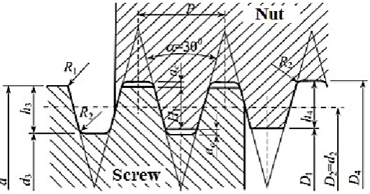
The stresses in the threaded spindle of car jack The tread spindle is analyzed only according to tensile stress. It is well-known that tensile stress is equal to ratio of force and cross section area. For the treaded spindle, the cross section area can be calculated approximately as circle where the diameter of circle is the arithmetic mean of diam-eters d2 and d3 (Figure 5).
The tensile stress in thread spindle is calcu-lated according to the equation:
𝜎𝜎𝑧𝑧=𝐹𝐹𝐴𝐴𝑉𝑉 𝑠𝑠=
𝐹𝐹𝑉𝑉 (𝑑𝑑22+ 𝑑𝑑 3 2)
2 ∙ 𝜋𝜋4
=(𝑑𝑑 8𝐹𝐹𝑉𝑉
22+ 𝑑𝑑32)𝜋𝜋 (10)
The number of turns of the threaded nut can be calculated using the following equation:
𝑧𝑧 =𝑝𝑝 𝐹𝐹𝑉𝑉
𝑑𝑑∙ 𝑑𝑑2∙ 𝜋𝜋 ∙ 𝐻𝐻1 (11)
where: Fv– load force of threaded spindle, d2 – thread spindle middle diameter, d3– thread spindle core diameter, z – number of turns of threaded nut,
H1– depth of basic thread profile,
pd – maximum allowed contact pressure
for steel on steel.
STRUCTURAL ANALYSIS OF CAR JACK
The structural analysis is one of the most common areas of research which use finite ele-ment method. FEM is type of analysis where ana-lyzed body is divided by a finite number of small volume elements, which are connected by joints [6, 7, 8, 9, 11, 12].
The numerical analysis was carried out using FEM in software CATIA V5. The procedure was divided into several steps.
The first step was to define finite elements. In this research, the finite elements were chosen in the form of tetrahedron with parabolic edge. This type of finite element needs to be chosen when there are some curved surfaces on the body, which is exactly the case in this research. This is especially important to successfully simulate the threaded spindle body.
The second step was to define the material for all parts of car jack. For the threaded spindle and threaded nut, steel 8.8 is chosen. For other parts of the car jack, standard construction steel is used, S235 and S275.
The third step of numerical analysis was to define loads and boundary conditions. The car jack has only one load at the top, which repre-sents part of the weight of whole car. According to the available car jacks on the market and pro-duction specifications, the maximum load of the car jack is 900 kg. The place of load is shown infigure 6. The boundary conditions need to be defined because some degrees of freedom for car jack parts must be restricted. Additionally, while using boundary conditions, all connections be-tween parts must be defined.
Defining the boundary conditions always starts with definitions of fixed parts. For the car jack, the fixed part during lifting is the stand (red part on Figure 6) and the fixed surface is
the bottom surface of stand (place reliance on Figure 6).
After defining all the above-mentioned steps, a solver numerically solved the finite elements equation system taking all defined boundary
conditions, connections and loads applied on car jack as inputs. After numerical calculation, postprocessing process had to be carried out. The results of FEM were shown by the software [13, 14, 15, 16, 3, 4].
The most important results for this type of research and analysis are the obtained displace-ments vectors, Von Mises stress and principals stresses direction and intensity (Figure 7 and 8).
RESULTS
The results of analytical and numerical calcula-tions for upper and lower rods are shown in Table 1. The maximal value of stress is in lower rod (107.7 MPa) in upper fibers of the rod. The minimal value of stress is in the same rod but in lower fibers (7.75 MPa). This is the proof that the rod is loaded with pressure which is not aligned with rod axis.
Figure 6. Defined loads and boundary conditions
a) b)
Figure 7. Postprocessing; a) displacements vectors, b) principals stresses
a) b)
Degrees of safety Sm and Sv (according to yield stress and according to tensile strength) are greater than 2, which is proof that selected mate-rials are good enough for car jack rods. Table 1 indicates that the error ranges from 2.6% for min-imal value of stress in lower rod, up to 5.2% also for minimal value of stress, but for upper rod. Taking into consideration the complexity of the numerical analysis, it can be concluded that value of error is satisfactory.
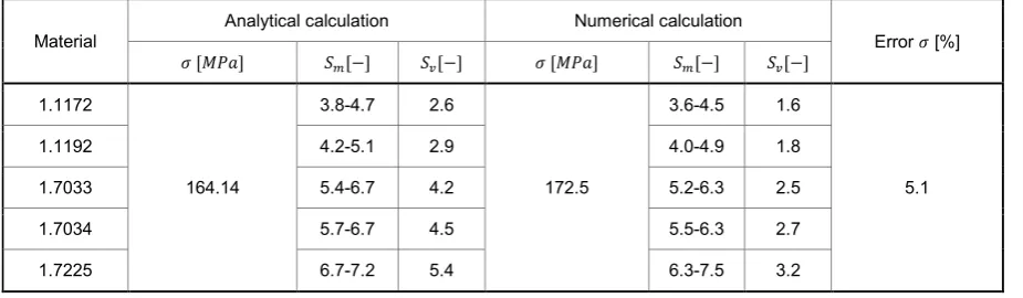
The results of analytical and numerical cal-culations for the threaded spindle are shown in Table 2. The error is this case is 5.1% which is satisfactory. Degrees of safety, according to yield stress, are satisfactory for both numeri-cal and analytinumeri-cal numeri-calculations for all materials. It can be concluded that this design of car jack will successfully work and deformation will be avoided (SM>3).
The reference degree of safety, according to tensile strength, is from 1.25 up to 2.5. It can be concluded that according to the analytical cal-culation, deformation will be avoided because the degree of safety for all materials is greater than the reference values. According to numeri-cal numeri-calculation, degrees of safety for materials 1.1172 and 1.1192 are inside references values.
For other three materials they are greater than reference values.
CONCLUSION
1. The goal of this paper was to develop a para-metric CAD model of a car jack. This model was used to carry out numerical structural anal-ysis of the car jack, according to the maximal load specified by the production specification. The materials for all car jack parts were chosen by referencing available literature and produc-tion specificaproduc-tions.
2. The created 3D parametric car jack model is a fully functional 3D model with all parameters and relations inside. Thus, conducting the nu-merical structural analysis was possible for all positions of the car jack during the lifting of a car. The numerical model of car jack includes defined part connection, loads and boundary conditions.
3. The numerical structural analysis was con-ducted when the car jack was at its lover posi-tion (at the beginning of car lifting), because that is the case when the car jack is maximally
Table 1. Results of calculation for car jack rods
Rod Material
Analytical calculation Numerical calculation Error [%]
𝜎𝜎𝑚𝑚𝑚𝑚𝑚𝑚 𝜎𝜎𝑚𝑚𝑚𝑚𝑚𝑚 𝑆𝑆𝑚𝑚 𝑆𝑆𝑣𝑣 𝜎𝜎𝑚𝑚𝑚𝑚𝑚𝑚 𝜎𝜎𝑚𝑚𝑚𝑚𝑚𝑚 𝑆𝑆𝑚𝑚 𝑆𝑆𝑣𝑣
𝜎𝜎𝑚𝑚𝑚𝑚𝑚𝑚 𝜎𝜎𝑚𝑚𝑚𝑚𝑚𝑚
[𝑀𝑀𝑀𝑀𝑀𝑀] [𝑀𝑀𝑀𝑀𝑀𝑀] [−] [−] [𝑀𝑀𝑀𝑀𝑀𝑀] [𝑀𝑀𝑀𝑀𝑀𝑀] [−] [−]
Upper S235 14.98 93.31 3.8-5.4 2.5 14.20 97.49 3.6-5.2 2.4 5.2 4.4
S275 4.8-6.2 2.9 4.6-5.9 2.8
Lower S235 7.75 107.7 3.3-4.7 2.1 7.96 103.7 3.4-4.9 2.2 2.6 3.7
S275 4.1-5.3 2.5 4.3-5.5 2.6
Table 2. Results of numerical and analytical calculations for threaded spindle
Material Analytical calculation Numerical calculation Error 𝜎𝜎 [%]
𝜎𝜎 [𝑀𝑀𝑀𝑀𝑀𝑀] 𝑆𝑆𝑚𝑚[−] 𝑆𝑆𝑣𝑣[−] 𝜎𝜎 [𝑀𝑀𝑀𝑀𝑀𝑀] 𝑆𝑆𝑚𝑚[−] 𝑆𝑆𝑣𝑣[−]
1.1172
164.14
3.8-4.7 2.6
172.5
3.6-4.5 1.6
5.1
1.1192 4.2-5.1 2.9 4.0-4.9 1.8
1.7033 5.4-6.7 4.2 5.2-6.3 2.5
1.7034 5.7-6.7 4.5 5.5-6.3 2.7
loaded. Using numerical structural analysis it was proven that the materials chosen for car jack parts meet the required stresses for ap-plied maximal load. The values of all stresses were in the reference range. The numerical structural analysis was performed in CATIA V5 software package.
4. The values of numerically obtained results were validated using analytical calculations for critical places at some parts of car jack. The balues of numerically obtained results devi-ate from the analytically obtained results in the range from 2.6% up to 5.2%, which can be considered as great results, taking into consid-eration the complexity of the car jack design. 5. The main conclusion of this research is that the
analyzed car jack design will successfully hold applied loads specified by the manufacturer, with satisfactory safety degrees. Development of this type of parametric 3D model enables easy change of the car jack position during lift-ing, which is especially suitable for design op-timization. Optimization of the car jack design can be subject of future research.
REFERENCES
1. Budynas, G.R., Nisbett, J.K. Shigley’s Mechani
-cal Engineering Design, 8th edition. McGraw-Hill Education, New York, 2008.
2. Chang S.D., Liaw H.S. Motor Driven Scissor Jack forAutomobiles. US Patent Number 4653727, Da Li Hsien, TW, 1987.
3. Delić, M., Čolić, M., Mešić, E. and Pervan, N. Analytical Calculation And FEM Analysis Main Girder Double Girder Bridge Crane. TEM Journal.
6(1), 2017, 48–52.
4. Delić, M., Pervan, N., Čolić, M. and Mešić, E. The -oretical and experimental analysis of the main girder
double girder bridge cranes. International Journal of
Advanced and Applied Sciences, 6(4), 2019, 75–80. 5. Farmer D.E. Automatic Jack and Wheel Change Sys
-tem. US Patent Number 6237953, Mt. Gay, WV, 2001.
6. Mešić, E., Avdić, V., Pervan, N. and Repčić, N. Fi -nite element analysis and experimental testing of
stiffness of the Sarafix external fixator. Procedia Engineering, 100, 2015, 1598–1607.
7. Mešić, E., Pervan, N., Repčić, N. and Muminović, A. Research of influential constructional param
-eters on the stability of the fixator Sarafix. Annals of DAAAM for 2012 & Proceedings of the 23rd
International DAAAM Symposium „Intelligent Manufacturing & Automation: Focus on Sustain
-ability”, Editor: Katalinic B., Zadar, Croatia, Octo -ber 24th-27th, 2012, 561–564.
8. Mešić, E., Avdić, V. and Pervan, N. Numerical and experimental stress analysis of an external fixation system. Folia Medica Facultatis Medicinae Uni -versitatis Saraeviensis, 50(1), 2015, 74–80. 9. Mešić, E., Muminovic, J. A. and Repčić, N. Geomet
-rical modelling and structural analysis of the Sarafix fixator configurations. Annals of DAAAM for 2012 & Proceedings of the 23rd International DAAAM Symposium „Intelligent Manufacturing & Automa
-tion: Focus on Sustainability”, Editor: Katalinic B., Zadar, Croatia, October 24th-27th, 2012, 69–74.
10. Mickael, E. Motor Driven Scissor Jack with Limit Switches. US Patent Number 6695289 B1, 2004.
11. Muminovic, J. A., Saric, I. and Repcic, N. Numeri
-cal Analysis of Stress Concentration Factors. Pro
-cedia Engineering, 100, 2015, 707–713.
12. Muminovic, J. A., Braut, S., Muminovic, A. and
Saric, I. Numerical and analytical analysis of
elas-tic rotor natural frequency. TEM Journal, 3(4),
2014, 323–328.
13. Pervan, N., Mešić, E., Čolić, M. and Avdić, V. Stiffness Analysis of the Sarafix External Fixator based on Stainless Steel and Composite Material. TEM Journal, 4(4), 2015, 366–372.
14. Pervan, N., Mešić, E. and Čolić, M. Stress analysis of external fixator based on stainless steel and com
-posite material. International Journal of Mechanical Engineering & Technology, 8(1), 2017, 189–199.
15. Pervan, N., Mešić, E., Čolić, M. and Avdić, V. Stiffness analysis of the sarafix external fixator of composite materials. International Journal of Engi
-neering & Technology, 5(1), 2016, 20–26.
16. Pervan, N., Čolić, M., Šarić, I. and Hadžiabdić, V. Analysis of the Haulage Ropes on Ropeways in Case of Accidental Loads. TEM Journal, 5(2),
2016, 171–174.
17. Pickles J. Portable Powered Screw Jack Actuator Unit. US Patent Number 4749169, Troy, MI, 1988.
18. Saric I., Pervan N., Muminovic A. and Colic, M.
Development of Integrated Intelligent Cad System
for Design of Shafts. Tehnički vjesnik, 25(Supple -ment 1), 2018, 99–104.
19. Saric I. and Muminovic A. J. Development of in -tegrated intelligent CAD system for synthesis and stress-deformation analysis of pressure vessels.
In-ternational Journal of Engineering & Technology,
7(1), 2018, 147–151.
20. Whittingham R.P. Vehicle Jack. US Patent Number