DIFFERENT TECHNIQUES OF RIGID
INTERNAL FIXATION IN MANDIBULAR
ANGLE FRACTURES –
AN IN VITROSTUDY
Dissertation submitted to
The Tamil Nadu Dr. M.G.R. Medical
University
In partial fulfilment of the degree of
MASTER OF DENTAL SURGERY
BRANCH III
ORAL AND MAXILLOFACIAL SURGERY
Urkund Analysis Result
Analysed Document: URKUND CHECK.pdf (D46550380)
Submitted: 1/8/2019 4:32:00 PM
Submitted By: [email protected]
Significance: 5 %
Sources included in the report:
https://www.readbyqxmd.com/keyword/130029 https://www.ncbi.nlm.nih.gov/pubmed/29141673 https://scinapse.io/papers/2017961438
https://healthdocbox.com/Dental_Care/109283972-A-customized-fixation-plate-with-novel- structure-designed-by-topological-optimization-for-mandibular-angle-fracture-based-on-finite-element-analysis.html
Instances where selected sources appear:
“At times our own light goes out and is rekindled by a spark from another
person. Each of us has cause to think with deep gratitude of those who have lighted the flame within us.”
I bow in gratitude to the Almighty God, the creator, who has helped
me to sustain these best and toughest years of my life. For providing me the
immense strength and willpower to complete this work and to whom I owe my
very existence. I also thank the Almighty for His unparalleled grace, superior
protection and guidance throughout the lows and highs of my post graduate
journey. Thank you God for keeping my ship sailing and not failing me in my
journey.
I would like to express my deepest appreciation and sincere thanks to
my guiding light, my mentor and Guide Dr.Mathew Jose., Professor and
HOD, Department of Oral and maxillofacial surgery, Sree Mookambika
Institute of Dental Sciences, Kulasekharam. I thank him from the bottom of
my heart for his time, patience and unyielding faith in me. His constant and
timely advice, support and guidance inspired me to aspire for perfection and
has helped me to complete this dissertation. I could not have imagined for
having a better advisor and mentor for this study. I attribute the level of my
master’s degree to his encouragement and effort and without him this thesis
with whom I started this thesis work and many rounds of discussions on my
project with him, helped me a lot. He not only helped me with my thesis work
but also has influenced me with his level of knowledge, which he has
selflessly passed on to me. With his pearls of wisdom, he made the subject
interesting and understandable for our budding minds. He has constantly
forced me to remain focussed on achieving my goal. He is an example of a
true mentor and guide. I could not have asked for a better mentor or guide for
my post graduate studies. With all the gratitude that I feel and warm regards
that I can muster, I thank you sir for imbibing the precious seeds of
knowledge, patience, discipline and duty, that is a treasure for a lifetime.
I am deeply indebted to Dr.Sajesh, MDS, Professor, my co-guide,
who with his vast knowledge has helped me in my work theoretically as well
as clinically. He is a person with lots of clinical and laboratory knowledge and
at the same time he is very helpful and approachable. He acted as a strong
pillar of support who inspite of his own hectic schedule found time in
correcting this dissertation. He was always available to clear my doubts and
guide me to the light of knowledge with his valuable guidance, suggestions
and tireless pursuit for perfection. He has a strong personality and a heart full
of affection which helped me pass the tough times during my post graduate
programme. I am highly greateful to sir for converting the juvenile me into a
matured person under his wings of knowledge. His words always inspired me
student friendly and with his unique style of convincing the most
uncooperative patients and getting us out of trouble and who is always
approachable for any help at any time and he is the one who taught me how to
manage anxious and apprehensive patients giving me an insight of his
psychological approach.
I express my sincere gratitude to Dr.Sindhuja MDS, Senior lecturer,
also for exchanging her vast knowledge and skills during my post graduate
programme which helped me to enrich my skills.
I express my sincere thanks to Dr. Elizabeth Koshi MDS, Principal,
Sree Mookambika Dental College, Kulasekharam for allowing me to utilize
the clinical material and facilities for the completion of this dissertation.
This endeavour would have been impossible without the help,
guidance and inspiration of Dr.A. Lenin Fred, Principal, Mar Ephraem
College of Engineering and Technology, Marthandam for giving me an
opportunity to conduct the study and for making the right arrangements and
conducting time to time meetings with the corresponding departmental staff. I
am indeed, indebted to him.
I express my sincere thanks to Mr. Leo Bright Singh, Professor,
Department of Mechanical Engineering, Mar Ephraem College of Engineering
with this finite elememt analysis, I am indeed, indebted to him.
I am thankful to Dr.Porchelvan for helping me with the statistical
analysis involved in this study. I am thankful to Dharshan offset printers for
their help in carrying out all the DTP works.
It gives me immense pleasure to thank Dr.Subin Varughese
Mathew, my co-PG, who has been with me throughout my postgraduate life
more like an elder brother, guiding and encouraging me during the happy and
hard moments making this journey a memorable one.
This acknowledgement seems lacking without the mention of my dear
super seniors Dr.Shameem Jamal, Dr. Swaminathan, seniors Dr. Abirami,
Dr. Harinee and my dear fellow Post graduates Dr. Aneesha, Dr. Yazhini,
Dr. C.Tamil Selvan and Dr. Saravana Kumar for providing a homely and
fun filled environment and also for their immense support, motivation and
constant encouragement when I slow down. I acknowledge my friends and
batchmates Dr.Swetha, Dr.Blessing , Dr.Tanuja and Dr.Amalor for their
unwavering moral support and motivation in accomplishing this The Greatest
task in my life.
I am also thankful to Mrs. Sunitha and Mrs. Suja Assistants,
Department of Oral and maxillofacial, SMIDS, for their sincere work that
Mrs.Seema and Ms.Priya, Office staffs, SMIDS for their sincere work that
helped me a lot all through my three years of Post Graduate life.
A wave of fond emotions sweep over me as I struggle to gather the
appropriate words, to express the insurmontable respect and warm gratitude I
feel for my father R.Selvaraj, my Mother Carmel Mary, my Brother
Bruno Joe, my Sister Linda, and my better half Dr. Divya M H for their
confidence in me and their sacrifices, strength and encouragement at all times
has been an inspiration and is solely responsible for refurbishing my life and
profession.
“In the end, though, maybe we must all give up trying to pay back
the people in this world who sustain our lives. In the end, maybe it's wiser
to surrender before the miraculous scope of human generosity and to just
SPECIAL ACKNOWLEDGEMENT
I take this opportunity to thank specially our Chairman
Dr.C.K.VELAYUDHAN NAIR MS, Sree Mookambika Institute of Dental
Sciences, our Director Dr.REMA.V.NAIR MD, Sree Mookambika Institute
of Dental Sciences and our Trustees Dr.R.V.MOOKAMBIKA MD, DM,
Dr.VINU GOPINATH MS, MCH and Mr.J.S.PRASAD, Adminstrative
officer for giving me the opportunity to utilize the facilities available in this
SL. NO
INDEX
PAGE NO
1
LIST OF ABBREVIATIONS i2
LIST OF FIGURES ii - iv3
LIST OF TABLES v - vi4
LIST OF GRAPHIC DIAGRAMS vii5
ABSTRACT 16
INTRODUCTION 3 - 77
AIMS AND OBJECTIVES 88
REVIEW OF LITERATURE 9 - 309
MATERIALS AND METHODOLOGY 31 - 3710
RESULTS AND OBSERVATIONS 38 - 5711
DISCUSSION 58 – 6312
SUMMARY AND CONCLUSION 64i
AO Association for the study of Internal Fixation
FEA Finite Element Analysis
BSSRO Bilateral Sagittal Split Ramus osteotomy
OMS Oral and Maxillofacial surgeons
IGES Initial Graphics Exchange Specifications
CAD Computer aided design
CT Computed Tomography
DICOM Digital imaging and communications in medicine
RS Resorbable screws
RCT Randomized Controlled Trials
CCT Controlled Clinical Trials
MAF Mandibular Angle Fractures
ii
Figure -1 Geometry of Group I
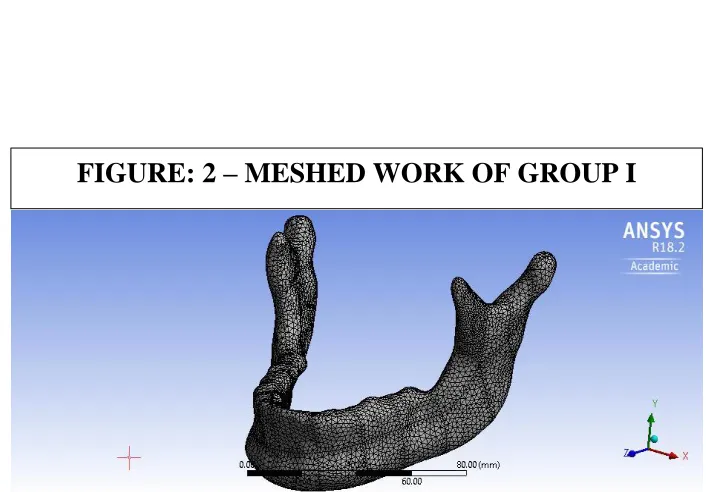
[image:17.595.99.524.86.735.2]Figure -2 Meshed Work of Group I
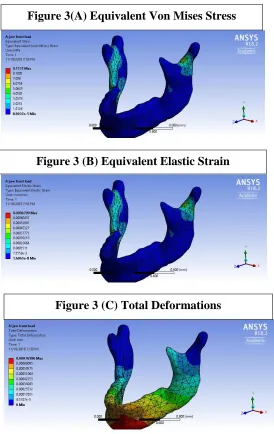
Figure -3
``Front Load in Group I 3(A) Equivalent Von Mises 3(B) Equivalent Elastic Strain 3(C) Total Deformation
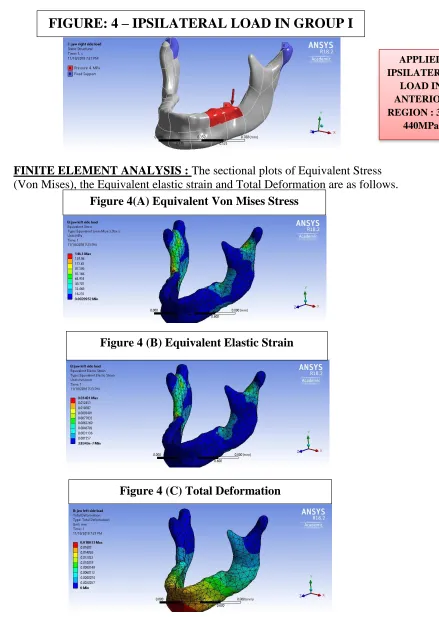
Figure-4
Ipsilateral Load in Group I 4(A) Equivalent Von Mises 4(B) Equivalent Elastic Strain 4(C) Total Deformation
Figure-5
Contralateral Load in Group I 5(A) Equivalent Von Mises 5(B) Equivalent Elastic Strain 5(C) Total Deformation
Figure-6 Geometry of Group II
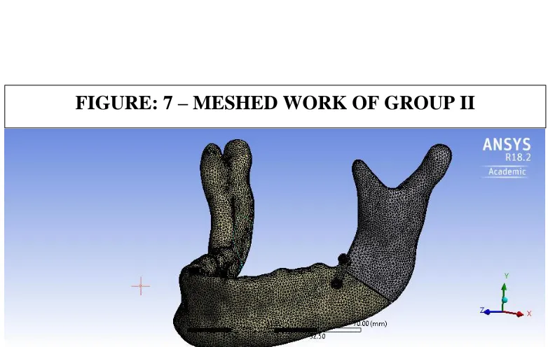
Figure-7 Meshed Work of Group II
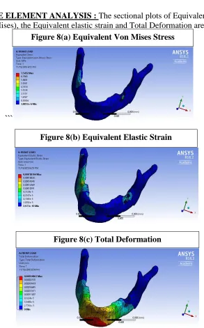
Figure-8
Front Load in Group II 8(A) Equivalent Von Mises 8(B) Equivalent Elastic Strain 8(C) Total Deformation
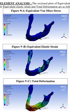
Figure-9
Ipsilateral Load in Group II 9(A) Equivalent Von Mises 9(B) Equivalent Elastic Strain 9(C) Total Deformation
Figure-10
Contralateral Load in Group II 10(A) Equivalent Von Mises 10(B) Equivalent Elastic Strain 10(C) Total Deformation
Figure-11 Geometry of Group III
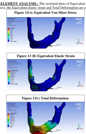
iii
13(B) Equivalent Elastic Strain 13(C) Total Deformation
Figure-14
Ipsilateral Load in Group III 14(A) Equivalent Von Mises 14(B) Equivalent Elastic Strain 14(C) Total Deformation
Figure-15
Contralateral Load in Group III 15(A) Equivalent Von Mises 15(B) Equivalent Elastic Strain 15(C) Total Deformation
Figure-16 Geometry of Group IV
Figure-17 Meshed Work of Group IV
Figure-18
Front Load in Group IV 18(A) Equivalent Von Mises 18(B) Equivalent Elastic Strain 18(C) Total Deformation
Figure-19
Ipsilateral Load in Group IV 19(A) Equivalent Von Mises 19(B) Equivalent Elastic Strain 19(C) Total Deformation
Figure-20
Contralateral Load in Group IV 20(A) Equivalent Von Mises 20(B) Equivalent Elastic Strain 20(C) Total Deformation
Figure-21 Geometry of Group V
Figure-22 Meshed Work of Group V
Figure-23
Front Load in Group V 23(A) Equivalent Von Mises 23(B) Equivalent Elastic Strain 23(C) Total Deformation
Figure-24
iv
vii
LIST OF GRAPHIC DIAGRAMS
GRAPH
NO:1
Graph depicting the Mean and Standard
deviation of Deformation in Group I, Group II,
Group III, Group IV, Group V with Front Load
values
GRAPH
NO:2
Graph depicting the Mean and Standard
deviation of Deformation in Group I, Group II,
Group III, Group IV, Group V with Ipsilateral
Load values
GRAPH
NO:3
Graph depicting the Mean and Standard
deviation of Deformation in Group I, Group II,
Group III, Group IV, Group V with
Contralateral Load values
GRAPH
NO:4
Graph depicting the Mean and Standard
deviation of Von Mises Stress in Group I, Group
II, Group III, Group IV, Group V with Front
Load values
GRAPH
NO:5
Graph depicting the Mean and Standard
deviation of Von Mises Stress in Group I, Group
II, Group III, Group IV, Group V with
Ipsilateral Load values
GRAPH
NO:6
Graph depicting the Mean and Standard
deviation of Von Mises Stress in Group I, Group
II, Group III, Group IV, Group V with
Contralateral Load values
GRAPH
NO:7
Graph depicting the Mean and Standard
deviation of Strain in Group I, Group II, Group
III, Group IV, Group V with Front Load values
GRAPH
NO:8
Graph depicting the Mean and Standard
deviation of Strain in Group I, Group II, Group
III, Group IV, Group V with Ipsilateral Load
values
GRAPH
NO:9
Graph depicting the Mean and Standard
deviation of Strain in Group I, Group II, Group
III, Group IV, Group V with Contralateral Load
1
Introduction :-
The frequent involvement of the mandibular angle in facial fractures can
be attributed to its thin cross-sectional bone area and the common presence of a third
molar. Before the advent of antibiotics, open reduction of mandibular fractures was
associated with a high frequency of infection.
Surgical intervention with stable internal fixation is warranted only if it
results in good anatomic reduction and provides the appropriate milieu for
undisturbed healing.
That is why in vitro biomechanical studies are so important for the development
of the clinical management of fractures. Finite element analysis (FEA) is a numerical
analysis technique that can determine the displacements, stresses, and strains over an
irregular solid body given the complex material behaviour and the loading conditions
imposed upon that body.
Aims and Objectives :-
To find the various stress distribution in mandibular angle fractures
using different plating techniques. The objective of the study is to compare the stress
distribution in bone under occlusal front, occlusal ipsilateral and occlusal
contralateral loads. To compare stress distribution along the angle of the mandible by
using 2.5mm 2 hole, 4 hole and 6 hole plates. To determine which plating technique
is the most ideal one in distributing stresses in the bone so that it will enhance the
2
Methodology :-
A three dimensional finite element model of the mandible with four different
plating techniques were modelled based on the measurements of a human dentulous
mandible using modelling software ‘Solidworks2018’ and was analyzed for stresses
produced in the bone following front, ipsilateral and contralateral biting loads of
different magnitude using ‘ANSYS 18.2 Workbench’.
Results
:-The results of the study indicated that two plating technique have more
favorable stress distribution in bone compared to other plating techniques.
Summary and Conclusion :-
Based on the observations in this study, it was concluded that two plating
technique showed more favorable stress distribution compared to other plating
techniques and could be considered for use with mandibular angle fractures. However
3
About 19–40 % of all facial fractures are fractures of the mandible, and
12–30 % of all mandibular fractures are fractures of the mandibular angle.1-2 Among
mandibular fractures, the angle is the first most frequent region for fractures caused
by sportive activities, the second most frequent region for fractures caused by
violence, and the third most fractured region in cases of traffic accidents involving
automobiles.3
The frequent involvement of the mandibular angle in facial fractures
can be attributed to its thin cross-sectional bone area and the common presence of a
third molar.4 Before the advent of antibiotics, open reduction of mandibular fractures
was associated with a high frequency of infection.5
Surgical intervention with stable internal fixation is warranted only if
it results in good anatomic reduction and provides the appropriate milieu for
undisturbed healing. If the fracture site is vulnerable to displacing forces, then the
advantages of early function are lost. Consequently, knowledge about the
biomechanical competence, or lack there of, of the individual fixation systems has
important therapeutic ramifications. It is essential that the treatment strategy have a
sound biomechanical basis. Determine the biomechanical competence of individual
fixation systems under controlled and repeatable conditions is an important tool to
investigate a variety of fixation devices and techniques and to optimize device design
on a rational basis.6
That is why in vitro biomechanical studies are so important for the
development of the clinical management of fractures. Finite element analysis (FEA) is
4
strains over an irregular solid body given the complex material behaviour and the
loading conditions imposed upon that body.7
The stress analysis obtained from FEA modelling can provide
information regarding interactions between hardware and bone during normal patient
functioning and perhaps suggest means of lowering the rate of postoperative
complications after open reduction and internal fixation (ORIF) of this trauma.8 So
this is an in vitro based study to biomechanically investigate the mandibular angle
fractures. This methodology is based on classic studies that establish the use of three
dimensional mandible.9
AN INTRODUCTION TO FINITE ELEMENT ANALYSIS
The Finite Element Analysis (FEA) is the simulation of any given
physical phenomenon using numerical technique for obtaining approximate numerical
solutions to the abstract equations of calculus it predicts the response of physical
systems subjected to external influences.
Finite element analysis is a computer aided mathematical technique
which will provide us with mathematical solutions, so the only way a response of a
system (physical or biological) can be predicted with a Finite element analysis is to
convert the problem from a physical/biological form to a mathematical form and later
on the mathematical solutions to the problem can be interpreted into physical/biologic
terms.
The four concept that are used in Finite element modeling are,
5
The system is typically a physical object composed of various materials, e.g.
solids, liquid, gases or combination of the above.
The domain of problem is typically the region of space occupied by the
system
The governing equations may be a differential equation, integral equation or a
constitutive equation describing the physical properties, & material behavior.
The Loading conditions are externally originating forces, temperature, etc.
that interact with the system causing the state of the system to change. Load acting in
the interior of the domain, i.e. interior load appears as part of governing equation.
Loads acting on the boundary of the domain i.e. boundary loads appears in separate
equation called boundary conditions.
STEPS IN FINITE ELEMENT ANALYSIS
Define a specific problem
•Geometry
•Physical Properties •Loads
Input data to program
•Geometry of domain mesh generation
•Physical properties
•Loads interior and boundary •Type of output desired
FINITE ELEMENT
PROGRAM
Output
•Select type of data •Generate related data
6
In this method domain of the problem is divided into smaller regions
called elements. Adjacent elements touch without over lapping and the there are no
gaps between the elements. The shape of the elements are intentionally made as
simple as possible, such as triangles or quadrilaterals in two dimensional domains
and tetrahedron, pentahedron (wedges or pyramids) and hexahedron (bricks) in three
dimensions. The entire mosaic like pattern of element is called a Mesh. The Mesh
generation is done by preprocessors. In each element the governing equations are
transformed into algebraic equations, called Element Equations, which are an
approximation of the governing equations. Algebraic equations are much easier to
work and are relatively easy to solve.
The terms in the element equations are numerically evaluated for each
element in the mesh, a process best performed on a computer. The resulting numbers
are assembled into a much larger set of algebraic equations called the System
equations. These characterize the response of the entire system so they usually
comprise of a very large number of equations, hundreds of thousands. Such huge
systems of equations can be solved economically because the matrix of coefficients is
"sparse".
Now the boundary conditions are applied which include the boundary
loads. These are imposed by modifying the system equations. This involves adding
values to existing terms and / or shifting terms from one side of the equations to the
other. Both are relatively simple operations.
The system equations are then solved on a computer using
conventional numerical analysis techniques that have been popular for many years,
7
The final operation, called post processing displays the solution to the
system equations in tabular, graphical, or pictorial form. Other physically meaningful
quantities might be derived from the solution and also displayed.
In this method, structures are subdivided into nodes and elements
which facilitates determination of the structural stiffness and ultimately deflection and
stresses (Force =stiffness x Deflection). Material properties such as the Young's modulus (modulus of elasticity) and Poisson's ratio can be utilized by computer generated analysis to describe the mechanical behavior and induced stresses and of a
structure. Calculation of these stresses allows the investigator to determine areas of
high stresses of large deformations which could lead to fracture or failure of the
structure. A general purpose finite element software provides the necessary tools to
perform such analysis for a wide variety of problems without compromising
8
AIMS:
To find the various stress distribution in mandibular angle fractures
using different plating techniques.
OBJECTIVES:
✓ To evaluate the biomechanical behaviour of bone and titanium mini
plates for rigid internal fixation in cases of mandibular angle fractures
using different load values.
✓ To compare the stress distribution in bone under occlusal front, occlusal
ipsilateral and occlusal contralateral loads.
✓ To compare stress distribution along the angle of the mandible by using
2.5mm 2 hole, 4 hole and 6 hole plates.
✓ To determine which plating technique is the most ideal one in
distributing stresses in the bone so that it will enhance the stability as
9
Mongini et al (1981)10said that the direct measurement of bone strain in
living human subjects is impractical, but efforts have been made to do so in
vitro on human material Qualitatively, these observations seem similar to those
in macaque, although direct comparisons are difficult to make. Photoelastic
measurements have also been made on physical models of the mandible, but this
technique does not lend itself to inclusion of in homogeneities in the jaw’s
physical properties.
Ashman et al. (1984)11 conducted a study Using an ultrasound
technique that measured the nine independent orthotropic elastic constants for
small specimens of bone. These specimens, taken from along the length and
around the periphery of human and canine femora, allowed us to map the spatial
variation of the elastic properties of these bones.
Ellis et al (1986)12 have shown that inadequate securing of the segments
can allow a displacement of the distal segment and initiate an early relapse in
animal studies. It has been shown that rigid fixation can provide sufficient
resistance to the displacing forces that encourage micro movements across the
osteotomy site. At the same time, an appropriate immobilization of the
osteotomy gap ensures an uncomplicated healing process, which guarantees
favorable long-term results.
Tom W.P. Korioth et al (1992)13 said that the morphology of bone is
10
variations in its cross-sectional shape and muscle disuse results in a decreased
bone mass. It is also possible that an increased vertical jaw depth is required in
the human mandible when it is called upon to produce high, molar biting forces.
The increased mandibular convexity, however, could also help withstand and
distribute the high corporal bone loads caused by vigorous mastication.
Edward Ellis et al (1993)14 treated sixty-five consecutive patients with
fractures of the mandibular angle by open reduction and internal fixation using
two dynamic compression plates placed through a trans oral incision using
transbuccal trochar instrumentation and 2.4-mm screws. In the first 20 cases, the
screws were inserted without tapping the drill holes. In the remaining 45 cases,
the drill holes were tapped. Overall, 21 fractures (32%) developed infections
requiring secondary surgical intervention. The infection rate was higher in those
fractures where the holes were not tapped (40%) than those cases when the
holes were tapped (29%). Of the 21 fractures that required hardware removal, 9
fractures were healed and required no further treatment; 12 had no firm bony
union and required postsurgical maxillomandibular fixation. Only one case
resulted in a malunion with resulting malocclusion. The use of two dynamic
compression plates was found to be relatively easy, but resulted in an
unacceptable rate of infection.
Niederhagen et al (1996)15 performed a prospective study of angle
fracture treatment over an 8-year period. One hundred eighty-three patients with
mandibular fractures were treated, noting 127 complications using the standard
11
most frequent complication was dehiscence. In addition, more complications
were noted (19.5%) when using the AO technique via an intraoral approach.
Comparison of extraoral AO treatment and monocortical miniplates showed no
significant difference in complication rate (8.1% vs 7.3%). During this study a
transition was made from the AO method to monocortical non compression
miniplates.ose: Similarities in strain patterns between long bones and the ma
Korioth et al (1997)16 described about mechanical finite element
analyses applied to the maxillary and mandibular bone with their associated
natural and restored structures. It includes a description of the principles and the
relevant variables involved, and their critical application to published finite
element models ranging from three-dimensional reconstructions of the jaws to
detailed investigations on the behavior of natural and restored teeth, as well as
basic materials science. The survey revealed that many outstanding FE
approaches related to natural and restored dental structures had already been
done 10-20 years ago. A numerical method for addressing mechanical problems
is a powerful contemporary research tool. FE analyses can provide precise
insight into the complex mechanical behavior of natural and restored
craniofacial structures affected by three-dimensional stress fields which are still
very difficult to assess otherwise.
Teixera et al (1998)17 concluded that in a 3-dimensional mandibular
model, modelling the mandible at distances greater that 4.2 mm mesially or
12
accuracy. The use of infinite elements can be a good way to model boundary
conditions.
Zhou et al (1999)18 Most FEA studies modelling the mandible set the
boundary conditions as fixed. Recently, Zhou et al developed a more realistic
3-dimensional mandibular FEA model from transversely scanned CT image data.
Maurer et al (1999)19 studied four different commonly accepted rigid
fixation methods which were chosen to undertake a comparison with each other
in a computer. A three-dimensional finite element analysis was selected to
evaluate the complex stress fields under posterior occlusal load condition in and
around rigid fixation screws and plates, which were used to stabilize the
proximal and distal segments after the BSSRO advancement procedure. The
three-dimensional finite element analysis allows for a more realistic
representation of the stress distribution in the fixative material and the adjacent
bone tissue than would be the case with a two-dimensional simulation.
Dirk Vollmer et al (2000)20 achieved a correlation coefficient of 99.2%
establishing confidence in the validity of the computed results. Due to a number
of simplifying assumptions made in the construction and in the analysis of the
FE model, comparison between experimental and mathematical data should
integrate the masticatory system implemented to evaluate the accuracy of the FE
model. One particular point of interest in the FEA is the analysis of various
biomechanical parameters (stress, strain and displacement) within the mandible.
13
of information on teeth, the lack of detailed knowledge regarding the material
properties of cancellous bone, the uncertainty of how to realistically distribute
the muscle loading and the difficulty of knowing how to model the boundary
conditions of the condyles. Therefore, validation of the model could only be
accomplished by comparing the computed results with observed and measured
responses. The results of the FEA in terms of strain distribution accorded well
with the experimental data.
Andrew J.L. Gear et al (2001)21 conducted a survey which showed
among 104 surgeons who treat mandible fractures, 86 (83%) treat more than 10
mandibular fractures per year. Preferred techniques for simple, non comminuted
mandibular angle fractures in this group were: single miniplate on the superior
border (Champy technique) with or without arch bars (44 surgeons, 51%);
tension band plate on the superior border and non locking, bicortical screw plate
on the inferior border (11 surgeons, 13%); dual miniplates (9 surgeons, 10%); a
locking screw plate on the inferior border only (6 surgeons, 7%), and
3-dimensional plates (5 surgeons, 6%). Eleven surgeons (13%) gave multiple
answers. Surgeons who treat more than 10 fractures per year favour the Champy
technique over the tension band and bicortical plate combination (44 [51%] vs
11 [13%]), while those surgeons who treat less than 10 per year favour the
tension band and bicortical plate combination over the Champy technique (9
[50%] vs 3 [17%]. This survey suggests an evolution in the management of
mandibular angle fractures. A single miniplate plate on the superior border of
14
When using large, inferiorly based plates more surgeons are now favouring
neutral rather than eccentric screw placement.
Gabreilli et al (2003)22, conducted a study and recorded of 191 patients
who experienced a total of 280 mandibular fractures that were treated with
2.0-mm miniplates were reviewed. One hundred twelve of those patients, presenting
160 fractures, who attended a late follow-up were also clinically evaluated.
Miniplates were used and no intermaxillary fixation was used. All patients
included had a minimum follow-up of 6 months. Demographic data, procedures,
postoperative results and complications were analyzed. Mandibular fractures
occurred mainly in males (mean age, 30.3 years). Mean follow-up was 21.92
months. The main etiology was motor vehicle accident. The most common
fracture was the angle fracture (28.21%). Twenty-two fractures developed
infection, for an overall incidence of 7.85%. When only angle fractures are
considered, that incidence is increased to 18.98%. Although only 1 patient
(0.89%) described inferior alveolar nerve paresthesia, objective testing revealed
sensitivity alterations in 31.52% of the patients who had fractures in regions
related to the inferior alveolar nerve. Temporary mild deficit of the marginal
mandibular branch was observed in 2.56% of the extraoral approaches
performed and 2.48% presented with hypertrophic scars. Incidence of occlusal
alterations was 4.0%. Facial asymmetry was observed in 2.67% of the patients,
whereas malunion incidence was 1.78Mean mouth opening was 42.08 mm.
Mercedes gallas torreira et al (2004)23 conducted a computer based
study which was made to assess the stress patterns within human mandibles
15
nodes and 30.119 tetrahedra. A commercial finite element solver was then
applied to this mesh to compute stresses generated in standard trauma situations
(a blow in the symphysis region and another one to the body of the mandible).
The results indicate that following a blow to the symphysis region, maximum
stress areas were located at the symphysis, retromolar and condylar regions. In
the case of a blow to the mandibular body, the maximum stress areas were
located at the contralateral angle, the ipsilateral body and the ipsilateral
condylar neck regions.The main application of this study was the prediction of
fractures as a consequence of known forces.
A H Choi et al (2005)24 studied a newer design (CAD) methods and to
16
E. Erkmen et al. (2005)25 created a three dimensional finite element
model of the mandible to simulate and study the biomechanical loads of
osteosynthesis screws in bilateral sagittal osteotomy. Using the finite element
method clinical conditions were simulated. When bite forces were applied, the
most stable configuration was found to be a triangular one. A mini screw of 2.0
mm diameter can provide sufficient stability at the osteotomy site after ramus
split osteotomy. Even screws with a diameter of 1.5 mm would withstand forces
up to 89.5 N, which would not normally be reached by patients after ramus split
osteotomy in the early period of healing. Forces exerted by patients after
bilateral ramus split osteotomy do not exceed these values. The finite-element
analysis appears to be an adequate method to evaluate this clinical question of
interest. It might well replace mechanical models and the results are comparable
with those reported in the International literature.
Chacon et al (2005)26 found that the scale of displacement was less for
the titanium plating system compared with the resorbable system. There is only
1 previous study that has compared titanium and resorbable plating systems for
the treatment of mandibular angle fractures, in a single cadaveric mandible; that
study showed significant biomechanical differences between the 2 materials.
Scott T. Lovald et al (2006)27, conducted a study on the finite element
model of the human dentate mandible has been developed to provide a
comparison of fixation systems used currently for fracture reduction. Volume
domains for cortical bone, cancellous bone, and teeth were created and meshed
in ANSYS 8.0 based on IGES curves created from computerized tomography
17
simulated along the symphysis. Results based on Von Mises stress in cortical
and cancellous bone surrounding the screws, and on fracture surface spatial
fixation, show some relative differences between different screw-plate systems,
yet all were judged to be appropriate in their reduction potential.
Conor P. Barry et al (2007)28 conducted a study to determine the
complication rate for patients presenting with isolated mandibular angle
fractures treated by open reduction and internal fixation using a single superior
border miniplate technique. This was a retrospective study of consecutive
patients with isolated mandibular angle fractures treated using a specific
protocol at a Regional Oral and Maxillofacial Department between January
1998 and December 2004. The study population included 50 patients presenting
with isolated mandibular angle fractures, 6 patients (12%) experienced
complications requiring bone plate removal. These complications were minor
and occurred after fracture healing as follows: 4 patients (8%) experienced
superficial soft tissue infection associated with the bone plate, treated with oral
antibiotics, 1 patient (2%) experienced bone plate exposure, and a further
patient (2%) presented with a fractured bone plate. All 6 patients (12%) were
treated by bone plate removal under general anesthesia as elective day case
surgery. The results of this study suggest that the complication rates associated
with the treatment of isolated mandibular angle fractures using a superior border
plating technique, in this patient population, is relatively low (12%). The
complications were all minor in nature. There was a permanent inferior alveolar
18
Alper Alkan et al (2007)29 evaluated the biomechanical behaviors of
different miniplate fixation techniques for treatment of fractures of the
mandibular angle. Twenty sheep hemimandibles were used to evaluate 4
different plating techniques. The groups were fixated with Champy technique,
biplanar plate placement, monoplanar plate placement, and 3-dimensional
curved angle strut plate. A custom-made 3-point biomechanical test model was
used for the samples. Each group was tested with compression forces by an
Instron Lloyd LRX machine. The 3D curved angle strut plate technique had
more favorable biomechanical behavior than the Champy technique but was not
significantly different from biplanar or monoplanar plate placement techniques.
The study demonstrated that 3D strut plates or dual miniplate techniques had
greater resistance to compression loads than the Champy technique. In addition,
biplanar plate orientation may provide a more favorable biomechanical behavior
than monoplanar plate placement.
Randal H Rudderman et al (2008)30 reviewed the behavior of the
human mandible. Behavior of the intact mandible, multiple fracture scenarios,
and small and large (single and multiple) plating applications are reviewed.
Several misconceptions in the literature are clarified. Factors that will resolve
the dichotomy between clinical results and current biomechanical theories are
presented such that a more logical biomechanical model may be used to
approach fixation of the mandibular fracture being treated. Current mandibular
biomechanics theory must be expanded to reflect the complex nature of the
system and to more accurately describe conditions that exist in the physical
world. Otherwise, further analysis in advancements in outcome and treatment
19
Hamdi arbag et al (2008)31, did a computer based finite
element analysis (FEA) to assess the most suitable shape and fixation technique
for a certain type of mandible fracture at corpus. A model of the mandible was
prepared using computed tomography scans. The CT scans were transferred and
converted to the finite element model by means of a procedure developed for
this study. Simulated corpus fractures were fixed with 14 different fixation
configurations of titanium miniplates. The FEA was performed with respect to
displacement and stresses in the titanium miniplates for these configurations.
The study results indicated that the use of 2 straight miniplates is more rigid
than other fixation types. FEA may be useful in evaluation of other plate
constructs, fracture types, and fracture sites, as confirmed by the agreement
between our data and those in the literature and with clinical experience. This
analysis should permit us to suggest and evaluate new miniplate designs and
enable considerable savings to be made in terms of time, material, and animal
experiments in the future development of osteosynthesis materials and
techniques.
Burak Bayramto et al (2009)32 performed a study, in order to
compare the fixation reliability and stability of titanium and resorbable plates
and screws by simulating chewing forces. Mandibular angle fractures in 11
sheep hemimandibles were fixed with 4-hole straight titanium plates and
2.0x7mm titanium screws; in addition, 11 hemimandibles were fixed with
4-hole straight resorbable plates and 2.5x6mm resorbable screws according to the
Champy technique. The hemimandibles were mounted with a fixation device in
20
under 20, 60, 100, 120, 150, and 200 N; maximum displacements; and
maximum forces that the model could resist before breakage were recorded and
compared. Significant differences were found between resorbable and titanium
plates and screws at all forces (20, 60, 100, 120, 150, and 200 N). We found no
statistically significant differences in the breaking force and maximum
displacement values (displacement values at the breaking forces) between the
groups. The stability of mandibular angle fractures with titanium miniplates
under simulated chewing forces was significantly higher than with the
resorbable system. Metallic and resorbable fixation systems cannot be used
interchangeably to treat mandibular angle fractures under similar loading
conditions.
Rudolf Seemann (2010)33, studied about the complication rates of
mandibular angle fractures treated by open reduction were assessed. Three
hundred twenty-two patients (259 men, 63 women) with 335 surgically treated
mandibular angle fractures were included in this study. Fractures were caused
by fights (46.6%), falls (19.2%), traffic accidents (14.6%), sports (11.9%),
wisdom tooth removal (7.3%), and 0.9% other causes. Successful treatment
occurred in 93.69% of fractures with 1 open reduction and in 6.31% with 2 open
reductions. Of surgically treated patients, 71.47% (238) were completely free of
complications. A detailed complication correlation matrix is given in the text.
Ninety-five fractures treated with 1 miniplate, 170 with 2 miniplates, and 70
with other osteosynthesis concepts were compared regarding osteosynthesis
failure and pseudarthrosis. Similar osteosynthesis failure rates were shown for 1
21
Eran Regevet al (2010)34 carried a study to use the meta-analysis tool
to combine information from multiple studies and to compare complication
rates for different fixation methods. An English language literature search was
conducted for articles on mandibular angle fractures. Information was collected
on four variables of interest: compression/noncompression technique,
monocortical/bicortical screws, number of plates, and location of plates. Five
outcome rates were analyzed: infection, reoperation, hardware removal,
malunion, and nonunion. Meta-analyses were run using Comprehensive Meta
Analysis, version 2.2.03. Significantly higher rates of infection, reoperation, and
hardware removal were found for compression compared with noncompression,
two plates compared with one plate, and for plates located on both the inferior
and superior borders as compared with superior or inferior only. The results of
this meta-analysis found lower complication rates with the use of
noncompression, monocortical, and single-plate fixation, supporting the trend
toward a single, superiorly placed, monocortical miniplate for fixation of
mandibular angle fractures.
Hang Wang et al (2010)35, did a study to analyze the stress
distribution in a symphyseal fractured human mandible reduced by 2 different
methods, reduction with 1 miniplate or with 2 miniplates by using finite element
(FE) analysis, and then compared the results with an intact mandible.
Three-dimensional FE models of an intact mandible and symphyseal fractured
mandibles reduced by 2 fixation methods were developed to analyse mandibular
22
clenching in the inter cuspal position and left unilateral molar clenching. Groups
of parallel vectors were used to simulate 9 pairs of masticatory muscles
involved in the 2 static biting tasks. Stress distributions in reduced mandible
with 1 or 2 miniplates were more or less different from that of the intact
mandible. During left unilateral molar clenching, bite forces obviously reduced
after fracture. Bite force and the stress distribution pattern in the mandible
reduced with 2 miniplates were closer to that in the intact mandible. It is
suggested that the effect of the miniplates in stabilizing the continuity-broken
mandible influence the restorations of the stress distribution pattern and bite
force. Two miniplates have a biomechanical advantage over 1 miniplate on
these restorations.
Jae Pyong Choi et al (2010)36 evaluated the stress distribution of
resorbable screw (RS) and cortical/cancellous bone in the mandibular setback
surgery with bilateral sagittal split ramus osteotomy (BSSRO) according to
fixation geometry and number of RSs using three-dimensional finite element
analysis. Three-dimensional virtual models of the mandible and bicortical RS
(INION CPS System; diameter, 2.5 mm; length, 12 mm [Inion Ltd, Tampere,
Finland]) were constructed by Mimics (Materialise,AnnArbor,MI) using three
dimensional computed tomography DICOM data with 0.5-mmthickness cut.
After 8-mm setback BSSRO was performed, fixation between the proximal and
distal segments of the mandible was done with bicortical RS. After applying the
occlusal load of 132 N on the lower first molar, stress distributions of the RSs
and cortical/ cancellous bone in each option were analyzed by ANSYS program
23
anterior RS fixation in the retromolar area in all options. Although 3R1A
fixation showed more even distribution of stress concentration than other
fixation options, 2R1A fixation was comparable with 3R1A fixation in view of
yield stress in RSs. In terms of fixation geometry and number of RSs, both
2R1A and 3R1A fixation configurations might provide proper stress distribution
in BSSRO.
Okumura N et al (2010)37 investigated the effect of maxillary
cortical bone thickness, implant design and diameter on stress around
implants and revealed that regardless of load direction, implant design
and diameter, cortical and cancellous bone stresses increased with the
decrease of crestal cortical bone thickness.
Syed Zakaullah et al (2011)38 did a study to evaluate the short-term
results of patients treated with low-profile titanium miniplates for fracture of the
mandible. Twenty patients with fractures of the mandible were treated by open
reduction and internal fixation using thin, low-profile titanium miniplates and
1.3-mm self-threading screws. Patients were evaluated for complications during
a 6 months follow-up period. One patient (5%) experienced wound dehiscence
and was managed by daily irrigation and antibiotic medication. Conclusion:
Low-profile titanium miniplates can be adequately used for internal fixation in
selective mandibular fractures.
Andre Vajgel et al (2013)39, conducted a study computational,
laboratory-based comparison of the biomechanical stability of 2.0 fixation
24
using 3-dimensional finite element analysis. Three-dimensional finite element
models simulating Class III atrophic mandibular 1.5, 2.0, and 2.5 mm. Fractures
were simulated in left mandibular bodies, and 3 locking screws were used on
each side of each fracture for fixation. Bite forces of approximately 63 N were
simulated in the incisor and molar regions of the mandibles in finite element
models. The level of compressive strain on the bone around the screw was
within the physiological limit. No significant difference was observed in the
displacement of bone segments in the fracture region. Von Mises stress was
higher during simulated bites in the molar region for plates with thicknesses of
1.0 mm. Plate tension values were below the level required for permanent
deformation or fracture in all models. The 2.5mmthick plate presented better
biomechanical performance than all other plates. The 2.0 mm thick plate also
showed satisfactory results and adequate safety limits. Large-profile (2.0 mm
thick) locking plates showed better biomechanical performance than did 1.0 and
1.5mm thick plates and can be considered an alternative reconstruction plate for
the treatment of Class III atrophic mandibular fractures.
Essam Ahmed Al-moraissi et al (2014)40 et al designed and
implemented a systematic review with meta-analysis. Only those studies where
a transoral approach was used (+/- transbuccal instrumentation) were selected.
21 publications were included: eight RCTs, three CCTs and ten retrospective
studies. Eight studies showed a low risk of bias, eleven studies showed a
moderate risk of bias, and one study showed a high risk of bias. There was a
statistically significant difference between a single superior border miniplate
25
meaning that the use of the oneminiplate in the fixation of MAFs decreases the
risk of postoperative complications by 37% compared to using two miniplates.
Comparing a miniplate placed on the external oblique ridge to one placed on the
lateral surface of the mandible resulted in a cumulative OR of 2.10, meaning
that the use of the transbuccal miniplate decreases the risk of postoperative
complications by 110% compared to one on the external oblique ridge.
Comparing geometric to standard miniplates, the OR was 0.29, meaning that the
use of a geometric miniplate decreases the risk of postoperative complication by
71% compared to using conventional miniplates.
Svetlana Anticto et al (2015)41 did a study inorder to investigate the
influences of the presence and position of a lower third molar (M3) on the
fragility of mandibular angle and condyle, using finite element analysis. From
computed tomographic scans of a human mandible with normally erupted M3,
two additional virtual models were generated: a mandibular model with partially
impacted M3 and a model without M3. Two cases of impact were considered: a
frontal and a lateral blow. The results are based on the chromatic analysis of the
distributed von Mises and principal stresses, and calculation of their failure
indices. In the frontal blow, the angle region showed the highest stress in the
case with partially impacted M3, and the condylar region in the case without
M3. Compressive stresses were dominant but caused no failure. Tensile stresses
were recorded in the retromolar areas, but caused failure only in the case with
partially impacted M3. In the lateral blow, the stress concentrated at the point of
impact, in the ipsilateral and contralateral angle and condylar regions. The
26
stresses caused the failure on the ipsilateral side, whereas compressive stresses
on the contralateral side.
Russell Wang et al (2016)42 conducted a study to simulate stress
and strain distribution numerically on a normal mandible under physiological
occlusal loadings. The results were compared to those of mandible that had an
angle fracture stabilized with different fixation designs under the same loadings.
The amount of displacement at two interfragmentary gaps also was studied. A
3D virtual mandible was reconstructed with an angle fracture that had a fracture
gap of either 0.1mm or 1mm. Three types of plate fixation designs were used:
Type I, a mini-plate was placed cross the fracture line following Champy
technique; Type two, two miniplate were used; Type III a reconstruction plate
was used on the inferior border of the mandible. 100N and 500N loads were
applied to the models. Results represent high stresses and strains distributed to
condylar and angular areas regardless of the loading position. The ratio of the
plate/bone average stress ranges from 215% (Type II design) to 848% (Type 1
design), irrespective of the interfragmentary gap size. With a 1 mm fracture gap,
the ratio of the plate/bone stress ranged from 204% (Type II design) to 1130%
(Type 1 design). Interfragmentary gaps between 0.1 mm to 1 mm did not have a
great effect of average stress distribution to the fractured bony segments;
however, they had a greater effect on the stress distribution to the plates and the
screws. Type II fixation was the best mechanical design under bite loads. Type I
design was the least stable system that had the highest stress distribution and the
27
Aysa Ayali et al (2018)43 did a study to evaluate the performances of
5 different plating 3 techniques for fixation of favourable mandibular angle
fractures using the 3D finite element analysis (FEA) method. Five different
miniplate placement configuration alternatives were considered for the fixation
of favorable mandibular angle fractures. The following models were created: a
double parallel miniplate (M1), which was placed at the halfway point of the
mandibular angle height; a ⅓ superior-positioned miniplate (M2); a single
miniplate (M3), which was placed at the halfway point of the mandibular angle
height (½ middle-positioned); a ⅓ inferior-positioned miniplate (M4); and an X
miniplate (M5). Double and ⅓ inferior-positioned miniplates provided the
lowest mechanical stress when compared with the other configurations, whereas
½ middle-positioned single miniplate and X miniplate had the highest stress
levels. In cases of favorable mandibular angle fractures, the authors suggest that
the double miniplate or, if used alone, the ⅓ inferior positioned single miniplate
are adequate rigid fixation methods.
Yun‑feng Liu et al (2017)44 proposed this study to design a
customized fixation plate for mandibular angle fracture using topological
optimization based on the biomechanical properties of the two conventional
fixation systems, and compare the results of stress, strain and displacement
distributions calculated by finite element analysis (FEA). A three-dimensional
(3D) virtual mandible was reconstructed from CT images with a mimic angle
fracture and a 1 mm gap between two bone segments, and then a FEA model,
including volume mesh with inhomogeneous bone material properties, three
28
design a customized plate using topological optimization method, then the shape
of the plate was referenced from the stress concentrated area on an initial part
created from thickened bone surface for optimal calculation, and then the plate
was formulated as “V” pattern according to dimensions of standard mini-plate
finally. All maximum von Mises stresses of mandible were well below the
allowable stress of human bone, as well as maximum principal strain. And the
displacement diagram of bony segments indicated the effect of treatment with
different fixation systems.
Kazuhiro Murakami et al (2017)45 concluded in their study to
evaluate stresses in various types of plates placed for a virtually reduced
unilateral condylar fracture of the mandible using computed tomography–based
3-dimensional finite element (FE) models of a patient to select the optimal plate
system. A computed tomography–based FE model of the mandible of a patient
with a unilateral condylar fracture was constructed. The fracture was virtually
reduced and fixed with 1 straight titanium plate; 2 straight titanium plates; 2
straight poly-L-lactic acid plates; and 4-hole (box), 5-hole (strut), and 7-hole
(lambda) condylar plates. Stresses developing in these plates were analyzed by
applying 478.1 N of bite force at the first molar of the contralateral side of the
mandible. The magnitudes of tensile stress were within the tensile strength in all
types of plates. However, the magnitudes of compressive stress in 1 straight
titanium plate and 2 straight poly-L-lactic acid plates were beyond the
compressive strength. The tensile and compressive stresses of the 5-hole (strut)
plate were the smallest among the 3 types of condylar plates. Fixation by 2
29
indicated for the condylar fracture of this patient. Among these plates, the
5-hole (strut) plate was considered optimal. FE analysis is useful in selecting the
optimal fixation method in the individual patient.
Kazem Khiabani et al (2018)46 in their study did the optimal method
for mini-plating in the fracture of the mandible angle to reach the best
mastication power. A three-dimensional model generated from CBCT
(Cone-beam computed tomography) of human mandible for Finite Element Analysis.
Four different fracture patterns were simulated on the models. Each fracture
pattern was fixed by five different methods of miniplate fixation. Each
compared to others after simulation and applying the force of the masticatory
muscles and result reported in Newton unit. The highest mastication force
belonged to a pattern in which a miniplate was placed on an outer oblique ridge
and another miniplate in the lower border of the buccal mandibular cortex. The
lowest mastication force also belonged to placing a mini plate on the upper side
of the cortex. However, this results show that the use of double miniplates will
improve biting force drastically and it is recommended to place 2 miniplates,
one on the external oblique ridge and the other on the inferior border of lateral
cortex.
Somsak Sittitavornwong et al (2018)47 studied The integrity of the
human mandibular angle fracture after fixation with a single titanium plate
along the upper lateral border to the native human mandible. This
cross-sectional anatomic study involved the left hemi-mandibles of sixteen human
cadavers. They were selected and divided in two groups by remaining dental
30
and gender were noted. The left hemisected native mandibles were mounted at
the condyle and loaded on an Instron 5565 mechanical unit until fracture. The
fractured left hemi-mandible was fixed with a titanium mini-plate and screws.
After plate fixation, each hemi-mandible was again loaded on an Instron 5565
until fracture. Data pertaining to primary outcomes of load application was
recorded in newtons at three different displacement values: 3.0, 5.0, and 7.0
mm, as well as displacement at fixation failure. Key clinical findings of this
project include the inability of single plate mandible fixation to restore the
mandible to pre-injury levels and verification that gender, dental status, and
height of the mandible do not alter the stability of a single plate fixated
mandible.
Bhat V et al (2014)48 compared and evaluated the
influence of different lengths of implants on stress upon bone in
mandibular posterior and concluded that under static horizontal loading
conditions, shorter implants transfer more stresses to the surrounding
bone and under static vertical loading they transmit lesser load to the
surrounding bone.
31
Finite element analysis is a typical work out of the method involves
dividing the domain of the problem into a collection of subdomains, with each
subdomain represented by a set of element equations to the original problem,
followed by 2 systematically recombining all sets of element equations into a
global system of equations for the final calculation. The global system of
equations has known solution techniques, and can be calculated from the initial
values of the original problem to obtain a numerical answer. In addition to
information about element and nodes, this model also contains information about
material and other properties, loading and boundary conditions.
Here modeling software ‘SOLIDWORKS-2018’ was used which is a solid modeling computer aided design (CAD) and computer aided engineering
(CAE) computer program. The structure of the human mandible of a complete
dentulous patient was transferred from the CT Scan and was converted in an
IGES (Initial Graphics Exchange Specifications) format onto the database. Once
a structure is numerically created and material properties are assigned it can be
analyzed for stress distributions during force application using finite element
software. The finite element software used in this study was ‘ANSYS 18.2’. The global (x, y, z directional axes) combination of the absolute values squared of all
stresses-is known as Von Mises stresses.
Finite element analysis is a numerical method based on the principle
of dividing a structure into finite number of small elements that are inter
connected with each other at the corner points or nodes having three degrees of
32
unique elastic properties (Poisson's ratio and modulus of elasticity) to represent
the materials modelled and for each elements, its mechanical behavior can be
written as a function of displacement of the nodes. These nodes are submitted to
certain loading conditions, resulting in behavior of the model similar to the
structures it represents. When a computer analysis is performed, a system of
simultaneous equations can be solved to relate all forces and displacements at
the nodes. From this stresses and stress contours can be established in each
element and thus for the whole body. This method has gained increased usage in
biomechanical disciplines including orthopedic, cardiac and dental mechanics.
SAMPLING:
Sample size of each group: 4
a. Total sample size of the study: 20
b. Scientific basis of sample size used in the study : n = 𝑍
2 𝑆2
𝑑2
n = Sample size = 20
Z = Value associated with confidence
S = Standard deviation of Mean 2.3 *
d = Absolute precision 1.2
* With reference to the study conducted by Raquel correia de Medeiros, eder alberto
sigua, Sergio olate, Pablo Navarro, in 2016
Formula → Patrikson S ; In textbook of Public Health and community medicine , Ist
Ed , 2009
Sample size = 20
Here 15 is the total sample size
c. Sampling Technique: Not applicable.
d. Inclusion criteria:
33
Group II: 3D mandible with Angle fracture with 2.5mm 2-hole
titanium plate with gap with 6mm screws
Group III: 3D mandible with Angle fracture with 2.5mm 4-hole
titanium plate with 6mm screws
Group IV: 3D mandible with Angle fracture with 2.5mm 6-hole
titanium plate with 6mm screws.
Group V: 3D mandible with Angle fracture with 2.5mm 2-hole
titanium plate with gap on the External Oblique Ridge and 4-hole titanium
plate with gap with 6mm screws on the Lateral surface.
e. Exclusion criteria: Damaged specimen
System configuration
A computer with the following system configuration was used
➢ Windows edition- Windows 8, service pack 2
➢ Processor- Intel® Core ™ i7 CPU M 430@ 2.27GHz 2.26GHz
➢ RAM: 4.00GB
➢ 64-Bit operating system
The geometric model of mandibular body was constructed based on
the measurements of a human dentulous mandible derived from a CT Scan.
Geometry of the Mandible
The dentulous section of the mandibl