Volume 2010, Article ID 974652,13pages doi:10.1155/2010/974652
Research Article
Block Transmissions over Doubly Selective Channels: Iterative
Channel Estimation and Turbo Equalization
Kun Fang,
1Luca Rugini,
2and Geert Leus
11Faculty of Electrical Engineering, Mathematics and Computer Science (EEMCS), Delft University of Technology,
2628 CD Delft, The Netherlands
2Department of Electronic and Information Engineering, University of Perugia, 06125 Perugia, Italy
Correspondence should be addressed to Luca Rugini,[email protected]
Received 7 January 2010; Accepted 8 April 2010
Academic Editor: Xiaoli Ma
Copyright © 2010 Kun Fang et al. This is an open access article distributed under the Creative Commons Attribution License, which permits unrestricted use, distribution, and reproduction in any medium, provided the original work is properly cited.
Modern wireless communication systems require high transmission rates, giving rise to frequency selectivity due to multipath propagation. In addition, high-mobility terminals and scatterers induce Doppler shifts that introduce time selectivity. Therefore, advanced techniques are needed to accurately model the time- and frequency-selective (i.e., doubly selective) channels and to counteract the related performance degradation. In this paper, we develop new receivers for orthogonal frequency-division multiplexing (OFDM) systems and single-carrier (SC) systems in doubly selective channels by embedding the channel estimation task within low-complexity block turbo equalizers. Linear minimum mean-squared error (MMSE) pilot-assisted channel estimators are presented, and the soft data estimates from the turbo equalizers are used to improve the quality of the channel estimates.
1. Introduction
Broadband wireless communication systems require high transmission rates, giving rise to frequency selectivity caused by multipath propagation, and consequently to intersymbol interference (ISI). In addition, recent wireless communica-tion standards, such as WiMAX and Long-Term Evolucommunica-tion (LTE), also need to support high mobile speeds, leading to high-mobility terminals and scatterers that introduce Doppler shifts and time selectivity, that is, intercarrier inter-ference (ICI). Due to the concomitant presence of ISI and ICI, specialized techniques are necessary to counteract the related performance degradation. However, with a properly designed transceiver, time- and frequency-selective (i.e., doubly selective) channels can even provide multiplicative delay-Doppler diversity gains [1,2].
LTE is a major 3GPP step in next generation wireless networks [3]. The LTE physical layer relies on a multiple-access scheme based on orthogonal frequency-division mul-tiplexing (OFDM) in the downlink, and on single-carrier frequency-division multiple access (SC-FDMA) in the uplink [3]. In both cases, the transmission scheme is blockwise,
and a cyclic prefix (CP) is included in each data block in order to eliminate the ISI between consecutive data blocks. OFDM and single-carrier (SC) block transmissions share some similarities: since an SC system can be viewed as a discrete Fourier transform (DFT) precoded OFDM system [4], performance and complexity are comparable, but part of the complexity (i.e., an inverse DFT) is moved from the transmitter to the receiver [4]. However, there are also some important differences: with respect to OFDM, SC has a lower peak-to-average power ratio, and hence power-efficient terminals are suitable for the uplink [5]. However, both SC and OFDM systems suffer from doubly selective channels, and call for appropriate ICI mitigation methods.
for doubly selective channel equalization, which is more challenging due to the time variation of the channel. For OFDM systems with doubly selective channels, low-complexity minimum mean-squared error (MMSE) turbo equalizers have been proposed in [12, 13]. The turbo equalizers [12,13], which are based on frequency-domain processing, estimate the data either serialwise, that is, each subcarrier is sequentially equalized [12], or blockwise, that is, all subcarriers are jointly equalized [13]. For SC trans-missions over time-invariant frequency-selective channels, time-domain turbo equalization (see [6,7]) is traditionally more popular than frequency-domain turbo equalization [10]. However, recently, frequency-domain equalization has gained renewed interest, due to its reduced complexity for channels with significant delay spread [5]. For SC systems over doubly selective channels, a low-complexity iterative equalizer has been proposed in [14], which can be regarded as the time-domain counterpart of the iterative frequency-domain equalizer [15]. However, time-domain iterative equalizers are not suitable for channels with significant delay spread, since their complexity is quadratic in the channel length [14]. Besides, maximum likelihood and maximum a posteriori sequence estimators for SC and OFDM systems have been proposed in [16], which models the doubly selective channel using a basis expansion model (BEM).
In this paper, as a first contribution, we apply the block philosophy to design a low-complexity MMSE turbo equalizer for SC systems in doubly selective channels. To the best of our knowledge, all the turbo equalizers proposed so far for SC systems over doubly selective channels employ a serialwise data processing, that is, use a sliding window either in the time domain [14] or in the frequency domain [15,17]. However, since the presence of the CP makes the transmission scheme blockwise, block equalization becomes a valid alternative. We design our block turbo equalizer for SC systems in the frequency domain, in the same spirit of the turbo equalizers designed for OFDM in [13]. An interesting feature of the proposed block equalizer is its reduced computational complexity, which scales only linearly with the block length. As a result, for doubly selective channels with significant multipath delay spread, our frequency-domain approach is less complex than time-domain equalizers like [14]. To keep the complexity low, some ad-hoc approximations are required, so that the proposed block turbo equalization algorithm for SC turns out to be different from that for OFDM [13]. In this paper, a performance comparison between the proposed algorithm and [13] is also given.
The ICI caused by Doppler spreading also makes the channel estimation problem more difficult. Pilot designs and pilot-assisted channel estimation algorithms have been developed for SC over time-varying flat-fading channels [18], for SC over doubly selective channels [19, 20], and for OFDM over doubly selective channels [21,22]. All these papers, which employ a BEM for the channel, share the design principle that pilots and data are placed in such a way that they should remain orthogonal after transmission over the fading channel. Indeed, this criterion eliminates the data-to-pilot interference and hence it simplifies the channel
estimation task. (The same criterion also eliminates the pilot-to-data interference, whose cancellation is therefore not necessary.) However, in doubly selective channels, orthog-onal designs have two drawbacks. First, only approximate-orthogonal designs are really possible, since a doubly selec-tive channel cannot be perfectly diagonalized [23]. Second, a rate loss is introduced by the presence of zero symbols that are necessary to keep the almost orthogonality between data and pilots. On the other hand, nonorthogonal designs are also possible, such as the superimposed training approach developed in [24]. Actually, turbo-inspired iterative channel estimators can handle the data-to-pilot interference by means of reliability-based soft cancellation. In other words, the soft data estimates can be used to improve the quality of channel estimation, as shown by the adaptive iterative channel estimators [25,26].
As a second contribution of this paper, we present iterative (turbo-like) pilot-assisted channel estimators for both OFDM and SC block transmissions. Differently from the turbo-based channel estimators already proposed for SC transmissions over doubly selective channels [25, 26], the proposed turbo-like channel estimators are nonadaptive and hence more suitable for block transmissions. For both OFDM and SC cases, the proposed iterative channel esti-mators firstly estimate the time-domain channel exploiting the BEM, and then transform the time-domain channel into the frequency domain for equalization purposes. This strategy is similar to that used for OFDM doubly selective channel estimation in [21, 22]. However, differently from the channel estimators of [21, 22], the proposed channel estimators exploit the reliability of the estimated data and can thus also work in the presence of nonorthogonal pilot designs.
To keep low-complexity channel estimation processing, we assume that the pilot symbols are located in the same domain where the data symbols are placed, that is, we assume frequency-domain pilots for OFDM systems, and time-domain pilots for SC systems. Although this choice is mainly dictated by computational complexity benefits, it is consistent with almost-orthogonal pilot allocation strategies for doubly selective channels, which indeed suggest time-domain pilots for SC systems [19, 20], and frequency-domain pilots for OFDM systems [20].
The rest of this paper is organized as follows. InSection 2, we introduce the system model. Section 3 presents the proposed block turbo MMSE equalizer for SC systems.
Section 4 deals with the design of iterative MMSE pilot-assisted channel estimators, for both OFDM and SC systems. InSection 5, we evaluate and compare the performance of the proposed equalizer and of both channel estimators, by means of simulated results.Section 6concludes the paper.
Notation. We use upper (lower) boldface letters to denote matrices (column vectors). (·)Tand (·)H, and (·)†represent transpose, complex conjugate transpose (Hermitian), and pseudoinverse, respectively. [A]m,nindicates the (m+ 1,n+
1)th entry of the matrix A. We use the symbol ◦ and
Table1: QPSK symbol alphabet.
k 1 2 3 4
(αk,1,αk,2) (0,0) (1,0) (0,1) (1,1)
αk (+1 +√ i)
2
(−1 +i) √
2
(+1−i) √
2
(−1−i) √
2
is a diagonal matrix with the vector a on the diagonal. E(·) stands for the statistical expectation. The covariance matrix betweenxandyis defined as Cov(x,y)=E(xyH)−
E(x)E(yH). Finally,0
M×N andIN denote theM×Nall-zero
matrix and theN×Nidentity matrix, respectively.
2. System Model
We consider a single-user communication system with blockwise transmission, and a channel that is both frequency and time selective. The structure of both transmitter and receiver is shown in Figure 1. At the transmitter, the information bits are encoded with error correction coding, and the coded bits are interleaved and mapped into Nd
complex symbols, represented by the Nd × 1 vector sd,
and the data symbols are assumed to be uncorrelated. We define sp as the N
p ×1 vector that stands for the pilot
symbols, which are multiplexed withsd to form a block of
N = Nd +Np transmitted symbols s. For simplicity, we
consider unit-energy quaternary phase-shift keying (QPSK) with the symbol alphabet shown in Table 1. However, the equalizers and channel estimators proposed herein can be easily extended to other constellations, like in [8].
As far as the time dispersion of the channel is concerned, we adopt the standard assumption that the maximum channel order is equal to the CP length, both denoted by L, where L < N. This way, there is no interference between successive blocks, and the equalizer can be designed separately for each block. As a consequence, we can omit the block index from our notation.
At the receiver, after removing the CP, theN×1 received vectorytcan be expressed as
yt=HtPs+nt, (1)
where Ht is the N ×N time-domain channel matrix, P
denotes theN×Nprecoder matrix,srepresents theN×1 symbol vector consisting of the multiplexed pilot and data symbols, and nt stands for the N×1 noise vector, which
is assumed to be uncorrelated with the data symbols. The precoder is set to P = IN for SC systems, and P = FH
for OFDM systems, where F denotes the N ×N unitary DFT matrix. For simplicity, we assume thatntis a circularly
symmetric complex Gaussian noise vector, with zero mean and covariance matrix Rnt = E(ntnHt ) = σn2IN. At the
receiver, a length-N time-domain window can be applied after CP removal and before the DFT operation. In this case, the output vector after the DFT operation can be expressed as
yf =FWHtFHFPs+FWnt=HfFPs+nf, (2)
whereyf = FWyt,nf =FWnt,Hf =FWHtFH, andW =
diag(w), withwtheN×1 vector denoting the time-domain receiver window. Note that classical systems do not include windowing, that is,W=IN.
When the channel is time varying, Ht is no longer
circulant, and theN×Nfrequency-domain channel matrix
Hf becomes a nondiagonal matrix, giving rise to ICI, where
the ICI coupling is summarized by the nonzero offdiagonal elements of Hf. However, with a proper window design, Hf is cyclically banded, with the most significant elements
around the main diagonal, and on the upper-right and lower-left corners [12]. In this paper, we employ the minimum band approximation error windowing developed in [27], where the window w is obtained as a sum of complex exponentials. This choice permits the use of low-complexity equalization algorithms specially tailored to banded and cyclically banded matrices, as explained in [12,28]. Observe that the receiver windowing in [27] only requires some statistical knowledge about the channel time variation, and this knowledge does not even have to be very exact.
To simplify the equalization procedure, the matrixHf is
further approximated by its cyclically banded version
H=Hf ◦Θ, (3)
where Θ is the N×N cyclically banded circulant matrix, which has ones on the main diagonal, on the Bc
super-and Bc subdiagonals, and on the upper-right and
lower-left Bc-size corners, while the remaining entries are zeros.
The matrix bandwidth parameter Bc allows for a trade-off
between equalization complexity and performance, and it can be chosen according to some rules of thumb [12]. When windowing is included,Bcis usually much smaller than the
number of subcarriersN.
It can be observed that the transmitted data block s
represents a time-domain signal in SC systems, while it represents a frequency-domain signal in OFDM systems. This clearly explains why SC systems are more prone to multipath effects, which mix the data due to the associated ISI, while OFDM systems suffer from Doppler effects, which mix the data due to the associated ICI. Our equalizer will be designed in the frequency domain, with the goal of mitigating the interference caused by the offdiagonal elements ofH.
3. Low-Complexity Block Turbo Equalization
In order to derive frequency-domain block turbo equalizers for doubly selective channels, let us definesias theith QPSK
symbol ofs, and (si,1,si,2) as the related bits. The mean and
the variance of the symbolsiare denoted asmi =E(si) and
vi=Cov(si,si), respectively. Similarly, we havem=E(s)=
[m1,. . .,mN]T andV =Cov(s,s) =diag([v1,. . .,vN]T). As
far as theNddata symbols are concerned, the means and the
Source Channelencoder Interleaver Symbolmapper PrecoderP P/S + CP
S/P−CP WindowW FFTF equalizerMMSE PH IFFT
FH
Symbol demapper
Deinter-leaver
MAP decoder
Interleaver LLR updating
priors computation Channel
estimation
vi=Cov(si,si)
Ld e(si,j)
Le(si,j)
yt yf
s
s
mi=E(si)
h
Figure1: System model.
to the pilot symbol value, while the variance is zero, for all the iterations.
After each iteration of the equalizer, we update the means and the variances using the soft estimated symbols. Specifically, we need to calculate the extrinsic log-likelihood ratio (LLR),Le(si,j) = L(si,j | si)−L(si,j), where L(si,j) is
the a priori LLR and L(si,j | si) is the a posteriori LLR
[7,13]. To perform this calculation, we should derive the probability density function (PDF) p(si|si =s), which can
be approximated as Gaussian: p(si | si = s) = (1/πσi2)·
e−|si−μi|2/σi2, with meanμi =E(si |si =s) and varianceσ2
i =
Cov(si,si |si=s) [7,8]. As shown inFigure 1, the extrinsic
LLR Le(si,j) is passed to the decoder to generate a new
extrinsic LLRLd
e(si,j), which is added to the a priori LLR to
form the new a posteriori LLRLnew(si,j). The new a posteriori
LLR permits to update the means and the variances of the estimated symbols as in [7,13]:
Lnew
si,j
=Lsi,j
+Lde
si,j
,
mi,new= tanh
Lnew
si,1
/2+√−1·tanhLnew
si,2
/2
√
2 ,
vi,new=1−mi,new2.
(4)
The a posteriori LLRLnew(si,j) of the current iteration then
becomes the a priori LLRL(si,j) used in the next iteration.
In the first iteration, no prior information is available, and therefore the a priori LLR is zero. The whole procedure described above can then be repeated, depending on the chosen number of iterations.
In the next subsection, we present a block turbo equalizer for SC systems. The proposed equalizer is derived using a similar approach as in [13], which develops three block turbo equalizers for OFDM systems.
3.1. Block Turbo Equalization for SC Systems. In SC systems, the precoder is absent and therefore it is set toP=IN. In this
case, (2) can be rewritten as
yf =FWHtFHFs+FWnt≈Hsf+nf, (5)
where sf = Fs. Similarly to our previous notation, we
define sf,i as the ith symbol of sf, mf,i = E(sf,i) and
vf,i = Cov(sf,i,sf,i) as the means and the variances of the
frequency-domain symbols.
Given m and V as prior information, the equalizer exploits the means and the variances of the frequency-domain symbols. Sincesf = Fs, we have mf = E(sf) = Fm = [mf,1,. . .,mf,N]T, and Vf = Cov(sf,sf) = FVFH.
SinceVis diagonal,Vf is in general circulant but not
diag-onal, that is, it can not be written as diag([vf,1,. . .,vf,N]T).
However, as it will be explained later, dealing with a diagonal
Vf is crucial for complexity reasons. Therefore, to save
complexity, we replace Vf with its approximated version
Vf ◦IN obtained by setting its offdiagonal elements to
zero. Since the diagonal elements of Vf are equal, Vf ◦ IN = vt·IN is a scaled identity, with vt = (1/N)
N
k=1vk.
A similar approximation is sometimes used also in time-domain equalizers [7,8].
By usingmf,iandvf,ias prior information, a
frequency-domain linear MMSE equalizer can be obtained using the approach used in [13] (Equalizer III) for OFDM systems. In SC systems, this approach leads to
sf,i= 1
ti hH
i A−1
yf −Hmf
+mf,i, (6)
where hi is the ith column of H, A = HVfHH + Rnf, ti = hHi A−1hi, and Rnf = E(nfnHf). It should be observed
that, when Vf is approximated as diagonal, the matrix A
have used a cyclic bandLDLH factorization obtained by a convenient modification of [28], in the same spirit of the fast Cholesky factorization of [29]. An alternativeLU fac-torization algorithm could be derived using the divide-and-conquer method of [30]. Using the algorithms specifically tailored to cyclically banded matrices, the computational complexity per data block reduces toO(B2
cN), which is linear
in the block size N. On the contrary, the complexity of a time-domain equalizer would beO(L2N). Since the Doppler support Bc is usually much lower than the maximum
channel order L, our frequency-domain MMSE equalizer is computationally cheaper than the corresponding time-domain MMSE equalizer.
On the other hand, without any approximation on
Vf, A would not be cyclically banded, and therefore the
complexity order of MMSE equalizers would be O(N3). Since the block size N is by far greater than the Doppler support Bc, the diagonal approximation is necessary for
low-complexity MMSE equalizers. However, when moderate complexity is affordable, other approximations are possible. For instance, if Vf is approximated as cyclically banded
with bandwidthBv, the matrixAwould be cyclically banded
too, but the computational complexity would increase to
O((Bc +Bv)2N). Alternatively, a low-complexity weighted
least-squares (WLS) equalizer that avoids the approximation ofVf could be employed, by neglecting the noise covariance
matrix inside A. However, since doubly selective channels lead to highly ill-conditioned matrices, WLS equalizers produce a very poor performance. Indeed, MMSE equalizers can be interpreted as regularized WLS equalizers.
From (6), the estimated time-domain data-symbol vector is successively obtained bys=FHs
f, which leads to
si=iHi FHsf =iHi FH N
k=1
iksf,k
=iHi FH N
k=1 1 tkikh
H
kA−1HF(s−m) +iHi FH N
k=1
ikmf,k
+iHi FH N
k=1 1 tk
ikhHkA−1Fnt
=iH i FH
N
k=1 1 tk
ikhHkA−1HF(s−m) +iHi FH N
k=1
ikiHkFm
+iHi FH N
k=1 1 tkikh
H kA−1Fnt
=mi+iHi FHTΣF(s−m) +iHi FHTHHA−1Fnt,
(7)
whereikis theN×1 indicator function, defined as thekth
column ofIN,T=
N
k=1(1/tk)ikiHk is a diagonal matrix, and
Σ=HHA−1H.
In order to derive the extrinsic LLR, the meanμiand the
varianceσi2of the Gaussian PDFp(si|si=s) are calculated
from (7) as
μi=E(si|si=s)
=iHi FHTΣFE(s−(m−miii)|si=s)
=iH
i FHTΣFiis ≈s,
σ2
i =Cov(si,si|si=s)
=Esi−μi2|si=s
=EiHi FHTΣF[s−m−i
i(s−mi)]
+iHi FHTHHA−1Fn
t
2
=iH i FHTΣF
V−viiiiHi
FHΣHTHFi i
+σ2
niHi FHTΣH−1H−HΣHTHFii
≈vi+en,
(8)
where vi = (1/N)(
N
k=1vk −vi) = vt −vi/N and en =
(σ2
n/N)
N
k=1|hHkhk|−1. In (8), we have approximated the
matricesF(V−viiiiiH)FH,HHH, andΣby diagonal matrices,
by setting their offdiagonal elements to zero. As it will be explained later, similarly to the diagonal approximation of Vf, these approximations are necessary to maintain
a low complexity. We now separately discuss the three approximations.First, the approximation ofF(V−viiiiHi )FH
is similar to the approximation of Vf, which has been
discussed previously. However, now the obtained diagonal matrix is not a scaled identity.Second, since His cyclically banded, the offdiagonal elements ofHHHdecay to zero very
rapidly. Hence, we expect that the approximation onHHH
will not introduce a significant error.Third, the matrixΣ = HHA−1H represents the effect of a linear MMSE equalizer
HHA−1 applied to the channel matrixH. Since the MMSE equalizer highly mitigates the ICI, Σ is already very close to a diagonal matrix. This last approximation also leads to
TΣ≈IN, which justifies the equalizer unbiasednessμi≈si.
We now use the results in (8) to express the extrinsic LLR as [7,13]
Le
si,1
=lnp(si|si=α1)P2(0) +p(si|si=α3)P2(1) p(si|si=α2)P2(0) +p(si|si=α4)P2(1)
= √
8 Re(si)
vi+en
,
Le
si,2
=lnp(si|si=α1)P1(0) +p(si|si=α2)P1(1) p(si|si=α3)P1(0) +p(si|si=α4)P1(1)
= √
8 Im(si)
vi+en
,
(9)
It is easy to prove that the calculation of the extrin-sic LLR in (9) has complexity O(BcN). Therefore, the
equalization complexity of (6) dominates over the extrinsic LLR calculation complexity of (9). Taking into account FFT operations, the overall computational complexity per iteration for each block ofNsymbols isO((B2
c+ log(N))N),
which is independent of the channel lengthL. On the other hand, the complexity of the time-domain equalizer of [14] is O(L2N). Therefore, for multipath channels with a long impulse response, we obtain a significant complexity saving. A more detailed discussion (i.e., flops count) about the computational complexity of banded turbo equalizers can be found in [13].
We highlight that the three diagonal approximations introduced in (8) are fundamental in reducing the com-putational complexity. For instance, if the full matrixΣ is used, the computation of σ2
i in (8) involves full matrices,
and therefore the computational complexity would be at least
O(N2). In this case, the complexity of the extrinsic LLR cal-culation (9) would dominate. Clearly, the nonapproximated equalizer would be useful only when the block size N is small, which is not feasible in long multipath channels due to the constraint N > L. Therefore, if low computational complexity is important, there is no way to avoid diagonal approximations. We also point out that, among the different possible ways to approximate the two matrices HHH and
Σas diagonal, the only reasonable approach is setting their offdiagonal elements to zero. Indeed, as explained after (8),HHH andΣ are almost diagonal. However, forF(V−
viiiiHi )FH, there exist different ways to approximate it as
diagonal. Neglecting the offdiagonal elements leads tovi =
(1/N)(Nk=1vk−vi), which could be replaced, for instance, by
vi=v=max{vk}Nk=1. Intuitively, the average approximation assigns to all the symbols the average reliability of all the symbols, whereas the maximum approximation assigns to all the symbols the reliability of the worst symbol estimate. In the simulation section, we compare the performance of both approximations.
4. Iterative Channel Estimation
The turbo equalizers presented in the previous section require the channel-state information (CSI) at the receiver. To acquire the CSI, we propose a modification of a pilot-assisted channel estimator presented in [21] for OFDM. Specifically, we modify the iterative linear MMSE channel estimator of [21] in such a way that it can operate in a turbo fashion. Therefore, besides the pilot symbols, we also use the soft data estimates originating from the turbo equalizer and the decoder. Indeed, after the first iteration, the soft data symbol estimates can be used as auxiliary pilot symbols, in order to improve the quality of the subsequent channel estimates [31]. For both OFDM and SC systems, our channel estimators produce an estimateHt of the
time-domain channel matrix Ht, and then translate Ht into the
frequency-domain cyclically banded matrix estimateH. The channel estimators are assumed to have perfect knowledge of the channel statistics, that is, the Doppler spectrum and the
power-delay profile. We highlight that the channel estimators considered in this paper are nonadaptive, that is, the CSI is newly estimated in each transmitted block, using both pilots and data. This way, severe time variation can be handled.
In pilot-assisted transmissions, there exist various approaches to design the pilot pattern. We can distinguish between two broad categories: multiplexed training and superimposed training [24]. In the multiplexed training case, each element of the transmitted vector contains either a pilot symbol or a data symbol, while in the superimposed case both pilot and data symbols are located in the same positions, typically distributed over the whole transmitted vector. In this paper, we assume multiplexed training, which is also known as periodic training when the pilots are placed in the time domain, and as orthogonal training when the pilots are located in the frequency domain. In particular, we focus on the pilot placement schemes developed in [19,20], which have been proved to be optimal in the MMSE sense under certain channel conditions. In these schemes, pilot symbols are interleaved with the data symbols to form the transmitted signal vector. For OFDM systems, we employ the frequency-domain Kronecker delta (FDKD) pilot structure [20], while, its dual scheme [19], identified as time-domain Kronecker delta (TDKD), is adopted for SC systems. In both cases, the pilot symbols are grouped into equidistant clusters, each having the same length. Within each cluster, a unique nonzero pilot symbol is located in the middle of the cluster, while null pilot symbols are placed on both sides. Therefore, the FDKD scheme coincides with equispaced pilot tones with guard frequency bands, while the TDKD scheme uses periodic training with guard time intervals.
Suppose that there areMpilot clusters, each containing Lp (odd) pilots, denoted by the vector smp of size Lp, for
m=0,. . .,M−1. These vectors are interleaved with the data clusterssd
m,m=0,. . .,M, to form the transmitted vectors,
as expressed by
s=sd
0 T
,s0pT,. . .,sd M−1
T
,sMp−1T,sd M
TT
. (10)
Therefore, by denoting withnm the starting position of the
mth pilot cluster, themth pilot vector contains the elements ofswith index starting fromnmup tonm+Lp−1. We also
define the aggregate pilot vector and the aggregate data vector as
sp=s0p T
,. . .,sMp−1 TT
,
sd =sd0 T
,. . .,sdMT
T ,
(11)
respectively, with sizeMLpandN−MLp, respectively.
In addition, we define htn,l as thelth channel tap at the
nth time instant, wherehtn,l=0 forl <0 orl > L, since the
maximal channel order is assumed to beL. Thus the elements ofHtcan be expressed as
[Ht]p,q=htL+1+p, mod (p−q,N), (12)
time domain. The BEM can be used to reduce the number of unknowns fromN(L+ 1) to (Q+ 1)(L+ 1), whereQ+ 1 is the number of basis functions [21]. By stacking all the channel taps within the block in a singleN(L+ 1)×1 vectorht =
[htL+1,0,. . .,htL+1,L,. . .,htL+N,0,. . .,htL+N,L]T, the BEM permits
to express this vector as
ht=(B⊗IL+1)h, (13)
whereB = [b0,. . .,bQ] is anN×(Q+ 1) matrix that has
Q+ 1 orthonormal basis functionsbqas columns, andhis a
(Q+ 1)(L+ 1) vector that collects all the BEM coefficients of all the channel taps.
In order to derive our MMSE channel estimator, the following assumptions are made.
Assumption 1. The wireless channel can be regarded as a wide-sense stationary uncorrelated scattering (WSSUS) process, which has the following statistics
E
ht t,l
ht
t−t,l−l
∗
=σ2
lδlγt, (14)
whereσ2
l denotes the variance of thelth channel tap,γtis the
normalized time correlation, andδnstands for the Kronecker
delta function.
Assumption 2. The data symbols in sd are assumed to be
uncorrelated with zero mean and variance σ2
s, while the
noise at the receiver is assumed to be uncorrelated with the transmitted symbols, as expressed by
E
sdsdH
=σ2
sIN−MLp,
EsnHt =0,
(15)
respectively.
Assumption 3. The BEM coefficientsh are assumed to be uncorrelated with the transmitted signal s and the noise, respectively, as expressed by
EhsH=0,
EhnHt =0.
(16)
Assumption 4. The covariance matrix of the BEM coefficients is assumed known to the receiver, and it is calculated as [21]
Rh=EhhH=Rh,l⊗diag
σ2
0,. . .,σL2
, (17)
whereRh,l=E(hlhHl )=B†R
{t}
h,lB†H, withhl=[h0,l,. . .,hQ,l]T
and [R{ht,l}]p,q=E(htp,l(htq,l)∗).
Assumption 5. The average power of the pilot symbols is the same as that of the data symbols, as expressed by
σs2=
(sp)Hsp
MLp .
(18)
4.1. Iterative Channel Estimation for OFDM Systems. For OFDM systems, the pilot and data symbols are interleaved in the frequency domain. Since the frequency-domain channel matrix is cyclically banded only approximately, the received samples used for channel estimation are always contami-nated by ICI, independently of the length of the null guard bands inserted. To be precise, the frequency-domain channel matrix is (with high probability) a full matrix, and hence the power of the pilot symbols is spread over all the received samples. While a time-domain receiver window can reduce the ICI to get a better equalization performance, it is still unclear whether the same window can improve the channel estimation quality or not. Thus, to estimate the time-domain channel matrixHt, we use the frequency-domain received
signalwithoutapplying the time-domain receiver window. For OFDM systems, the precoder is set toP =FH, and
(2) can be rewritten as
yf =FWHtFHs+FWnt≈Hs+nf. (19)
By substituting (13) in (19), we can rewrite (19) as
yf = Q
q=0
DqΔqs+nf, (20)
whereDq=Fdiag{bq}FH,Δq=diag{FL[hq,0,. . .,hq,L]}, and FLrepresents the firstL+ 1 columns of the matrix
√
NF. It is noteworthy that, for channel estimation purposes, it is not necessary to process all the received samples. Indeed, the computational complexity of the channel estimator can be highly reduced by extracting a subvector of yf before
channel estimation [21]. Obviously, this subvector should contain the relevant information given by the pilot symbols. Therefore, with reference to the mth pilot cluster smp, we
consider the following observation subvector
yf,m=
yf
nm−Δ,. . .,
yf
nm+Lp−1+Δ T
, (21)
where Δ is a smoothing parameter used to control the amount of interference taken into account for channel estimation. Please observe thatΔcan be positive as well as negative, or zero: WhenΔis positive, the channel estimator is actually enlarging the observation window, which in this case monitors also the 2Δdata symbol locations closest to the pilot symbols. The received signal in (21) can also be expressed as
yf,m= Q
q=0
Dq,mΔqm+ Q
q=0
Dq,mΔq(s−m) +nf,m, (22)
whereDq,mis an (Lp+2Δ)×Nmatrix consisting of theLp+2Δ
rows ofDqwith indices fromnm−Δtonm+Lp−1 +Δ. It
After some tedious manipulations, we can rewrite (22) as a function ofhas
yf,m=Dm
IQ+1⊗
diag(m)FL
h
+Dm
IQ+1⊗
diag(s−m)FL
h+nf,m
=Pmh+df,m+nf,m,
(23)
where Dm = [D0,m,. . .,DQ,m], and Pm = Dm{IQ+1 ⊗ [diag(m)FL]}. Stacking theMobservation clusters together,
we obtain the reduced-size frequency-domain received signal expressed by
yof =DoI Q+1⊗
diag(m)FL
h
+DoI Q+1⊗
diag(s−m)FL
h+nof
=Poh+do f +nof,
(24)
where yof = [yTf,0,. . .,yTf,M−1]T, dof = [dTf,0,. . .,dTf,M−1]T, and no
f = [nTf,0,. . .,nTf,M−1]T are column vectors of size M(Lp+ 2Δ),Do = [DT0,. . .,DTM−1]T, andPo = Do{IQ+1 ⊗ [diag(m)FL]}.
As a result of (24), the linear MMSE estimation of the BEM channel coefficients can be expressed by
h=RhPoHPoRhPoH+Rdo f +Rnof
−1
yof, (25)
whereRdo f =E(d
o
fdoHf ), andRnof =E(n
o
fnoHf ). We can express Rdo
f asRdof =D
oR
xDoH, where
Rx=
IQ+1⊗
diag(s−m)FL
RhIQ+1⊗
diag(s−m)FL
H
=IQ+1⊗diag(s−m)
IQ+1⊗FL
RhIQ+1⊗FL
H
×IQ+1⊗diag (s−m)H
=IQ+1⊗diag(s−m)
XIQ+1⊗diag (s−m)H
, (26)
whereX=(IQ+1⊗FL)Rh(IQ+1⊗FL)H, which can be further
simplified using the assumptions in (15)–(17) as
[Rx]m,n
⎧ ⎨ ⎩
vmod (m,N)[X]m,n, if mod (m−n,N)=0,
0, otherwise. (27)
After the estimation of the BEM coefficients inh, the time-domain channel vector can be reconstructed by (13) asht =
(B⊗IL+1)h, whose elements form the estimated time-domain
channel matrixHt.
In [21], it has been shown that the BEM-based linear MMSE channel estimator can achieve a better performance
by using a larger number of observation samples, that is, when all elements of yf are included in the observation
vectoryof. Obviously, the same behavior is expected in our case: Indeed, our channel estimator additionally includes the reliability of the turbo-equalized data symbols, and hence additional benefit should be obtained by including more data locations into the observation window. However, the main complexity of our channel estimator comes from the matrix inverse in (25), which requires the observation vector length to be small. Thus, the smoothing parameterΔallows for a trade-offbetween channel estimation complexity and performance.
4.2. Iterative Channel Estimation for SC Systems. Unlike OFDM systems, where the pilot symbols are inserted in the frequency domain, and the frequency-domain channel matrix is cyclically banded only approximately, in SC systems the pilots are positioned in the time domain, and the time-domain channel matrix is banded, due to the FIR channel assumption. Therefore, using sufficiently long guard intervals, the ISI between pilots and data is completely eliminated [19], thereby simplifying the channel estimation procedure.
Due to the banded structure of the time-domain channel matrix, when the guard intervals are large enough, themth pilot cluster only contributes to the time-domain received signal [[yt]nm,. . ., [yt]nm+Lp−1+L]
T. Similarly to the OFDM
case, we consider themth observation vector
yt,m=
yt
nm−Δ,. . .,
yt
nm+Lp−1+L+Δ T
, (28)
where the smoothing parameterΔis defined as in (21), but now operates in the time domain. Using the expressions (12) and (13), we can rewrite the time-domain received signal (1) as [21]
yt,m=Ht,mm+Ht,m(s−m) +nt,m
= Q
q=0
diagbq,m
Cq,mm
+
Q
q=0
diagbq,m
Cq,m(s−m) +nt,m
=Pmh+dt,m+nt,m,
(29)
whereHt,m consists of the corresponding rows ofHt, with
indices from nm −Δ to nm + Lp − 1 + L+ Δ, bq,m =
[[bq]nm−Δ,. . ., [bq]nm+Lp−1+L+Δ]
T,C
q,mis an (Lp+L+ 2Δ)×N
Cq,m=
⎛ ⎜ ⎜ ⎝
01×(nm−L−1−Δ) hq,L · · · hq,0 01×(N−nm+Δ) ..
. . .. . .. ...
01×(nm+Lp+Δ−2) hq,L · · · hq,0 01×[N−(nm+Lp−1+L+Δ)] ⎞ ⎟ ⎟
⎠, (30)
andPm=ZmUm, where
Zm=
diagb0,m
,. . ., diagbQ,m
,
Um=IQ+1⊗Tm,
Tm=
⎛ ⎜ ⎜ ⎝
mnm−Δ · · · mnm−L−Δ ..
. . .. ...
mnm+Lp−1+L+Δ · · · mnm+Lp−1+Δ ⎞ ⎟ ⎟ ⎠.
(31)
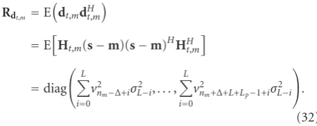
The covariance matrix of the interference termRdt,m can be calculated as
Rdt,m =E
dt,mdHt,m
=EHt,m(s−m)(s−m)HHHt,m
=diag ⎛ ⎝L
i=0 v2
nm−Δ+iσ 2
L−i,. . ., L
i=0 v2
nm+Δ+L+Lp−1+iσ 2
L−i
⎞ ⎠.
(32)
Stacking the M observation clusters together, we get the reduced-size time-domain received signal
yto=Poh+dot +not, (33)
where yo
t = [yTt,0,. . .,yTt,M−1]T, Po = ZU, with Z = diag[Z0,. . .,ZM−1] andU = [UT0,. . .,UTM−1]T, anddot and not are defined similarly toyto.
Like in the OFDM case, the linear MMSE estimate of the BEM channel coefficients can be derived as
h=RhPoHPoRhPoH+Rdo t +Rnot
−1
yo
t, (34)
whereRdo
t andRnot are similarly defined as in (25), andRdot = diag(Rdt,0,. . .,Rdt,M−1). It is easy to understand that, also in
this case, a better performance is achieved by including a larger number of observation samples [21], that is, by increasing the smoothing parameter Δ, at the price of increased complexity.
5. Simulation Results
In this section, the proposed algorithms are examined and compared by simulations. We consider a block transmission system with block lengthN =256. A rate 1/2 convolutional code with generator polynomials (5, 7) (in octal notation) and codeword length of 16384 is used. We employ random interleaving. The maximum channel delay spread and the CP length are equal to L = 7. The channel is assumed to
be Rayleigh distributed with uniform power-delay profile E{|hn,l|2} =1/(L+ 1),l=0,. . .,L, and with Jakes’ Doppler
spectrum [32,33]. We consider a high-mobility case where the normalized Doppler frequency is fdT = 0.15/N with
fd the absolute Doppler frequency shift and T the symbol
period. It can be interpreted as fd/ξ = 0.15 with ξ the
subcarrier spacing in OFDM systems. The time-domain receiver window of [27], as well as the cyclically banded equalizers, are designed for a matrix bandwidth parameter Bc = 3, unless otherwise stated. We use the generalized
complex-exponential (GCE) BEM to model the time-varying channel at the receiver [21]. Note that the (critically sampled) complex-exponential (CE) BEM would produce a cyclically banded channel matrix estimate, where the number of BEM parametersQ+ 1 coincides with the number of estimated diagonals. On the contrary, the GCE-BEM produces a full channel matrix estimate: Hence, this choice permits to increase the equalizer bandwidthBc, so that the number of
equalizer diagonals 2Bc+ 1 can exceed the number of BEM
parameters Q+ 1. The channel decoder employs a linear approximation to the log-MAP decoding algorithm.
Figure 2 shows the bit error rate (BER) performance of (the iterative block) Equalizer III [13], equipped with the proposed channel estimator for OFDM systems, as a function of the signal-to-noise ratio (SNR), which is defined as SNR = 1/σ2
n. We insert MLp = 10 frequency-domain
pilot symbols, grouped intoM =10 clusters, which means Lp=1, that is, there are no guard bands around the nonzero
pilot in each cluster. Therefore, the efficiency isη = (N−
MLp)/(N+L)= 0.94. We use the GCE-BEM withQ = 4.
The observation length parameter is set to Δ = 2, which leads to a total observation length ofM(Lp+ 2Δ)= 50 for
each block. It is clear that most of the performance gain is obtained when passing from one iteration, which represents the noniterative equalizer, to two iterations. In addition, it is relevant that the performance gain obtained by iterative equalization with respect to the noniterative equalizer is higher in case of estimated CSI: For instance, at BER=10−3, the performance gain is more than 3 dB. The performance gain with respect to noniterative approaches is confirmed by
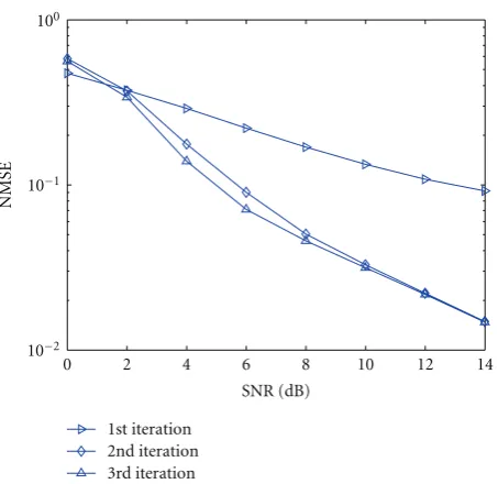
Figure 3, which displays the normalized mean square error (NMSE) of the iterative MMSE channel estimator, defined as NMSE = E{ht −(B⊗IL+1)h 2/N}. Notably, the first iteration of our channel estimator coincides with the linear MMSE channel estimator of [21].
We now compare the BER performance of the iterative block equalizer for OFDM [13], assuming different choices for the basis functions used by the channel estimation algorithm proposed in this paper. Here we assumeBc = 2,
while the other parameters are the same ofFigure 2.Figure 4
100
10−1
10−2
10−3
10−4
10−5
10−6
BER
0 2 4 6 8 10 12 14
SNR (dB)
Perfect CSI, 1st iteration Perfect CSI, 2nd iteration Perfect CSI, 3rd iteration Estimated CSI, 1st iteration Estimated CSI, 2nd iteration Estimated CSI, 3rd iteration 10−7
Figure2: BER performance of OFDM systems.
100
10−1
0 2 4 6 8 10 12 14
SNR (dB) 10−2
1st iteration 2nd iteration 3rd iteration
NMSE
Figure3: Channel estimation performance of OFDM systems.
iterations. These results, obtained for soft-decision data-aided pilot-based channel estimation, are consistent with the results obtained in [21] for nondata-aided and covariance-data-aided pilot-based channel estimation.
Figure 5shows the BER performance comparison of the proposed iterative frequency-domain block turbo equalizer for SC systems with perfect CSI. We employ MLp = 52
time-domain pilot symbols, grouped into M = 4 clusters, which means there are (Lp−1)/2 =6 guard time symbols
on each side of the nonzero pilot in each cluster. In this case, the efficiency is η = (N −MLp)/(N + L) = 0.78.
0 2 4 6 8 10 12 14
100
10−1
10−2
10−3
10−4
10−5
10−6
SNR (dB)
BER
CE-BEM, 1st iteration CE-BEM, 2nd iteration CE-BEM, 3rd iteration
GCE-BEM, 1st iteration GCE-BEM, 2nd iteration GCE-BEM, 3rd iteration
Figure4: BER performance comparison of different basis functions for OFDM systems.
We now use a BEM orderQ = 2. The observation length parameter is set toΔ= −6, which leads to a total observation length of M(Lp + L + 2Δ) = 32 for each block. It can
be observed that the time-domain receiver windowing can improve the BER performance over the system without windowing [34] under doubly selective channels. With time-domain receiver windowing, the BER performances of the average approximation ofvi =(1/N)(
N
k=1vk−vi) and the
maximum approximation ofvi=v=max{vk}Nk=1in (8) are almost the same after three iterations.
Figure 6illustrates the BER performance of the proposed iterative frequency-domain block turbo equalizer for SC systems with average approximation, for both perfect and estimated CSI. It is shown that the second iteration of our block turbo equalizer achieves about 1.5 dB gain with respect to the first iteration, which corresponds to the output of a noniterative equalizer. However, a third iteration does not help. Figure 7plots the NMSE of the MMSE channel estimator. Note that, differently from the considered SC scenario, in OFDM systems we have not used any guard bands around the nonzero pilot tone. The reason is that in OFDM systems the ICI power has a rapid decay. On the contrary, since the considered channel has a uniform power-delay profile, it generates significant ISI. Thus, the iterative process is not capable of suppressing a lot of interference, and large guard intervals are needed to accurately estimate the CSI.
0 2 4 6 8 10 12 100
10−1
10−2
10−3
10−4
10−5
10−6
SNR (dB)
BER
No windowing, ave. approximation, 1st iteration No windowing, ave. approximation, 3rd iteration Windowing, ave. approximation, 1st iteration Windowing, ave. approximation, 3rd iteration Windowing, max. approximation, 1st iteration Windowing, max. approximation, 3rd iteration
Figure5: BER performance comparison of different equalization approaches for SC systems.
100
10−1
10−2
10−3
10−4
10−5
10−6
BER
0 2 4 6 8 10 12 14
SNR (dB)
Perfect CSI, 1st iteration Perfect CSI, 2nd iteration Estimated CSI, 1st iteration Estimated CSI, 2nd iteration
Figure6: BER performance of SC systems.
CSI after three iterations. The bandwidth parameter Bc =
3 is the same for both SC and OFDM systems. It can be shown that, as the values of Doppler spread and channel length increase, a lower BER can be achieved at high SNR. The simulation results confirm that both SC and OFDM systems benefit from channel coding, by obtaining delay and Doppler diversity, respectively, which is not fully exploited in the uncoded case. However, the achievable diversity gain is difficult to analyze, since the cyclic band approximation
100
10−1
0 2 4 6 8 10 12 14
SNR (dB) 10−2
1st iteration 2nd iteration
NMSE
Figure7: Channel estimation performance of SC systems.
0 2 4 6 8 10 12 14
SNR (dB)
fd=0.03,L=7
fd=0.15,L=2 fd=0.15,L=7 fd=0.03,L=2
100
10−1
10−2
10−3
10−4
10−5
10−6
BER
10−8 10−7
Figure8: BER comparison of OFDM systems.
error impairs the performance at high SNR, and the amount of diversity also depends on the specific error correction code used [5,35].
6. Conclusions
100
10−1
10−2
10−3
10−4
10−5
10−6
BER
0 2 4 6 8 10 12 14
SNR (dB) 10−7
fd=0.03,L=2 fd=0.03,L=7
fd=0.15,L=2 fd=0.15,L=7
Figure9: BER comparison of SC systems.
from the turbo equalizers are used to improve the quality of the channel estimates. Combined with error correction coding, both OFDM and SC systems can effectively exploit the delay-Doppler diversity provided by doubly selective channels.
Acknowledgments
The authors would like to thank one of the reviewers, who provided insightful comments and interesting suggestions. This research was supported in part by NWO-STW under the VIDI program (DTC.6577) and VICI program (DTC.5893). This paper was presented in part at the International Conference on Acoustics, Speech and Signal Processing, Las Vegas, NV, April 2008, and International Conference on Acoustics, Speech and Signal Processing, Taipei, Taiwan, April 2009.
References
[1] A. M. Sayeed and B. Aazhang, “Joint multipath-doppler diver-sity in mobile wireless communications,”IEEE Transactions on Communications, vol. 47, no. 1, pp. 123–132, 1999.
[2] X. Ma and G. B. Giannakis, “Maximum-diversity transmis-sions over doubly selective wireless channels,”IEEE Transac-tions on Information Theory, vol. 49, no. 7, pp. 1832–1840, 2003.
[3] 3GPP, “LTE Physical Layer—General Description,” TS 36.201 - v1.0.0, March 2007.
[4] Z. Wang and G. B. Giannakis, “Wireless multicarrier com-munications: where Fourier meets Shannon,” IEEE Signal Processing Magazine, vol. 17, no. 3, pp. 29–48, 2000.
[5] F. Pancaldi, G. M. Vitetta, R. Kalbasi, N. Al-Dhahir, M. Uysal, and H. Mheidat, “Single-carrier frequency domain equalization: a focus on wireless applications,” IEEE Signal Processing Magazine, vol. 25, no. 5, pp. 37–56, 2008.
[6] C. Douillard, M. Jezequel, C. Berrou, A. Picart, P. Didier, and A. Glavieux, “Iterative correction of intersymbol interference: turbo-equalization,”European Transactions on Telecommuni-cations and Related Technologies, vol. 6, no. 5, pp. 507–511, 1995.
[7] M. T¨uchler, R. Koetter, and A. C. Singer, “Turbo equalization: principles and new results,”IEEE Transactions on Communica-tions, vol. 50, no. 5, pp. 754–767, 2002.
[8] M. T¨uchler, A. C. Singer, and R. Koetter, “Minimum mean squared error equalization using a priori information,”IEEE Transactions on Signal Processing, vol. 50, no. 3, pp. 673–683, 2002.
[9] R. R. Lopes and J. R. Barry, “The soft-feedback equalizer for turbo equalization of highly dispersive channels,” IEEE Transactions on Communications, vol. 54, no. 5, pp. 783–788, 2006.
[10] M. T¨uchler and J. Hagenauer, “Turbo equalization using frequency domain equalizers,” inProceedings of the Allerton Conference, Monticello, Ill, USA, October 2000.
[11] H. Liu and P. Schniter, “Iterative frequency-domain channel estimation and equalization for single-carrier transmissions without cyclic-prefix,”IEEE Transactions on Wireless Commu-nications, vol. 7, no. 10, pp. 3686–3691, 2008.
[12] P. Schniter, “Low-complexity equalization of OFDM in doubly selective channels,”IEEE Transactions on Signal Processing, vol. 52, no. 4, pp. 1002–1011, 2004.
[13] K. Fang, L. Rugini, and G. Leus, “Low-complexity block turbo equalization for OFDM systems in time-varying channels,”
IEEE Transactions on Signal Processing, vol. 56, no. 11, pp. 5555–5566, 2008.
[14] S. Ahmed, M. Sellathurai, S. Lambotharan, and J. A. Cham-bers, “Low-complexity iterative method of equalization for single carrier with cyclic prefix in doubly selective channels,”
IEEE Signal Processing Letters, vol. 13, no. 1, pp. 5–8, 2006. [15] P. Schniter and H. Liu, “Iterative frequency-domain
equaliza-tion for single-carrier systems in doubly-dispersive channels,” inProceedings of the Asilomar Conference on Signals, Systems and Computers, vol. 1, pp. 667–671, Pacific Grove, Calif, USA, November 2004.
[16] I. Barhumi and M. Moonen, “MLSE and MAP equalization for transmission over doubly selective channels,”IEEE Trans-actions on Vehicular Technology, vol. 58, no. 8, pp. 4120–4128, 2009.
[17] B. K. Ng and D. Falconer, “A novel frequency domain equalization method for single-carrier wireless transmissions over doubly-selective fading channels,” inProceedings of the IEEE Global Telecommunications Conference (GLOBECOM ’04), vol. 1, pp. 237–241, Dallas, Tex, USA, November, 2004. [18] L. Tong, B. M. Sadler, and M. Dong, “Pilot-assisted wireless
transmissions: general model, design criteria, and signal processing,”IEEE Signal Processing Magazine, vol. 21, no. 6, pp. 12–25, 2004.
[19] X. Ma, G. B. Giannakis, and S. Ohno, “Optimal training for block transmissions over doubly selective wireless fading channels,”IEEE Transactions on Signal Processing, vol. 51, no. 5, pp. 1351–1366, 2003.
[20] A. P. Kannu and P. Schniter, “Design and analysis of MMSE pilot-aided cyclic-prefixed block transmissions for doubly selective channels,”IEEE Transactions on Signal Processing, vol. 56, no. 3, pp. 1148–1160, 2008.
[21] Z. Tang, R. C. Cannizzaro, G. Leus, and P. Banelli, “Pilot-assisted time-varying channel estimation for OFDM systems,”
[22] K. A. D. Teo and S. Ohno, “Pilot-aided channel estimation and viterbi equalization for OFDM over doubly-selective channel,” inProceedings of the IEEE Global Telecommunications Conference (GLOBECOM ’06), San Francisco, Calif, USA, December 2006.
[23] S. Barbarossa, “Eigenfunctions of underspread linear commu-nication systems,” inTime-Frequency Analysis, B. Boashash, Ed., Elsevier, Amsterdam, The Netherlands, 2003.
[24] S. He and J. K. Tugnait, “On doubly selective channel estimation using superimposed training and discrete prolate spheroidal sequences,”IEEE Transactions on Signal Processing, vol. 56, no. 7, pp. 3214–3228, 2008.
[25] R. Otnes and M. T¨uchler, “Iterative channel estimation for turbo equalization of time-varying frequency-selective channels,”IEEE Transactions on Wireless Communications, vol. 3, no. 6, pp. 1918–1923, 2004.
[26] X. Li and T. F. Wong, “Turbo equalization with nonlinear Kalman filtering for time-varying frequency-selective fading channels,”IEEE Transactions on Wireless Communications, vol. 6, no. 2, pp. 691–700, 2007.
[27] L. Rugini, P. Banelli, and G. Leus, “Low-complexity banded equalizers for OFDM systems in doppler spread channels,”
EURASIP Journal on Applied Signal Processing, vol. 2006, Article ID 67404, 13 pages, 2006.
[28] L. Rugini, P. Banelli, and G. Leus, “Simple equalization of time-varying channels for OFDM,” IEEE Communications Letters, vol. 9, no. 7, pp. 619–621, 2005.
[29] S.-J. Hwang and P. Schniter, “Efficient sequence detection of multicarrier transmissions over doubly dispersive channels,”
EURASIP Journal on Applied Signal Processing, Article ID 93638, 17 pages, 2006.
[30] M. Hegland, “Divide and conquer for the solution of banded linear systems of equations,” in Proceedings of the IEEE Symposium on Parallel and Distributed Processing (PDP ’96), pp. 394–401, Washington, DC, USA, January 1996.
[31] J. Bonnet and G. Auer, “Optimized iterative channel esti-mation for OFDM,” in Proceedings of the IEEE Vehicular Technology Conference (VTC ’06), pp. 1621–1625, Montreal, Canada, September 2006.
[32] W. C. Jakes,Microwave Mobile Channels, John Wiley & Sons, New York, NY, USA, 1974.
[33] Y. R. Zheng and C. Xiao, “Simulation models with correct statistical properties for Rayleigh fading channels,” IEEE Transactions on Communications, vol. 51, no. 6, pp. 920–928, 2003.
[34] K. Fang, L. Rugini, and G. Leus, “Low-complexity frequency-domain turbo equalization for single-carrier transmissions over doubly-selective channels,” in Proceedings of the IEEE International Conference on Acoustics, Speech and Signal Pro-cessing (ICASSP ’09), pp. 2541–2544, Taipei, Taiwan, April 2009.