FPGA-based Niederreiter Cryptosystem using
Binary Goppa Codes
Wen Wang1, Jakub Szefer1, and Ruben Niederhagen2 1 Yale University, New Haven, CT, USA
{wen.wang.ww349, jakub.szefer}@yale.edu
2 Fraunhofer SIT, Darmstadt, Germany
Abstract. This paper presents an FPGA implementation of the Nieder-reiter cryptosystem using binary Goppa codes, including modules for encryption, decryption, and key generation. We improve over previous implementations in terms of efficiency (time-area product and raw per-formance) and security level. Our implementation is constant time in order to protect against timing side-channel analysis. The design is fully parameterized, using code-generation scripts, in order to support a wide range of parameter choices for security, including binary field size, the de-gree of the Goppa polynomial, and the code length. The parameterized design allows us to choose design parameters for time-area trade-offs in order to support a wide variety of applications ranging from smart cards to server accelerators. For parameters that are considered to pro-vide “128-bit post-quantum security”, our time-optimized implementa-tion requires 966,400 cycles for the generaimplementa-tion of both public and private portions of a key and 14,291 cycles to decrypt a ciphertext. The time-optimized design uses only 121,806 ALMs (52% of the available logic) and 961 RAM blocks (38% of the available memory), and results in a design that runs at about 250 MHz on a medium-size Stratix V FPGA.
Keywords: post-quantum cryptography, code-based cryptography, Nie-derreiter cryptosystem, FPGA, hardware implementation.
1
Introduction
Arguably today’s most wide-spread asymmetric cryptographic algorithms are the Rivest-Shamir-Adleman (RSA) cryptosystem, Diffie-Hellman key exchange (DH), and a variety of primitives from the field of Elliptic-Curve Cryptogra-phy (ECC), e.g., ECDSA, EdDSA, ECDH, etc. These cryptosystems are based on the hardness of the integer-factorization problem and the discrete-logarithm problem. Using today’s computing systems, no efficient algorithms for solving these problems are known. However, the picture changes drastically if quan-tum computers are taken into account. In the 1990s, Shor proposed algorithms that can solve both the integer-factorization problem and the discrete-logarithm problem in polynomial time on a quantum computer [23,24]. In order to provide
alternatives to the threatened schemes, the field of Post-Quantum Cryptogra-phy (PQC) emerged in the 2000s and has received increased attention recently, most noticeably due to a standardization process for PQC schemes started by NIST in 2017 [7].
Currently, there are five categories of mathematical problems that are under investigation for PQC: code-based systems, lattice-based systems, hash-based systems, systems based on multivariate polynomial equations, and systems based on supersingular isogenies of elliptic curves [4,22]. Each of these categories has advantages and disadvantages. They vary in the performance measures (sizes of public and private keys, sizes of ciphertext and key-exchange messages, computa-tional cost, etc.) and in maturity: some schemes (e.g., some code-based schemes and hash-based signature schemes) are considered well-understood and there is a general agreement on the required security parameters while other schemes are more recent and the exact security that they provide is yet under investigation. Conservative and well-understood choices for code-based cryptography are the McEliece cryptosystem [18] and its dual variant by Niederreiter [19] using binary Goppa codes. In this paper, we focus on the Niederreiter cryptosystem. This cryptosystem has relatively large public keys of up to 1MB for roughly 256-bit classical security (corresponding to “128-256-bit post-quantum security” meaning that a quantum computer needs to perform at least 2128 “operations” using the best known attacks) using parameters proposed in [2]. There are more efficient PQC schemes than Niederreiter with binary Goppa codes. However, some of these schemes exhibit weaknesses that restrict their application to certain use-cases (e.g., Niederreiter with QC-MDPC codes instead of binary Goppa codes is affected by decoding errors [13] which restricts their use to ephemeral applica-tions without long-term usage of keys) while how to choose security parameters for some schemes is challenging (e.g., for some lattice-based schemes that have a security reduction, parameters need to be chosen either based on best-known attacks or based on the non-tight security reduction, which results in a dilemma of choosing either more efficient or more reliable parameters [1]).
changing widths of data paths, memories, and other parameters inside the de-sign, without affecting the security level. All of the parameters can be configured for key generation, encryption, and decryption.
Inspired by the confidence in the code-based cryptosystems, there are a few hardware implementations of different variants of these cryptosystems, e.g., [14,17,26]. Most of the work only focuses on the encryption and decryption parts of the cryptosystem due to the complexity of the key generation module. More-over, none of the prior designs are fully configurable as ours nor do they support the recommended “128-bit post-quantum security” level. We are aware of only one publication [26] that provides the design of a full McEliece cryptosystem including key generation, encryption and decryption modules. However, their design only provides a 103-bit classical security level, which does not meet the currently recommended security level for defending against quantum comput-ers. More importantly, the design in [26] is not constant-time and has poten-tial security flaws. For example, within their key generation part, they generate non-uniform permutations, and within the decryption part, they implement a non-constant-time decoding algorithm. Note that our work focuses on a design that can defend against timing side-channel attacks due to its constant-time im-plementation. However, other types of side-channel attacks are out of scope of this work. A detailed comparison with related work is presented in Section5. Contributions. This paper presents the first “128-bit post-quantum secure”, constant-time, efficient, and tunable FPGA-based implementation of the Nieder-reiter cryptosystem using binary Goppa codes. The contributions are:
– full cryptosystem with tunable parameters, which uses code-generation to generate vendor-neutral Verilog HDL code,
– new hardware implementation of merge sort for obtaining uniformly dis-tributed permutations,
– new optimization of the Gao-Mateer additive FFT for polynomial evaluation, – hardware implementation of a constant-time Berlekamp-Massey decoding
algorithm, and
– design testing using Sage reference code, iVerilog simulation, and output from real FPGA runs.
2
Niederreiter Cryptosystem
The private key of the Niederreiter cryptosystem is a binary Goppa codeG that is able to correct up toterrors. It consists of two parts: a generator, which is a monic irreducible polynomialg(x) of degreet over GF(2m), and a support, which is a random sequence ofndistinct elements from GF(2m). The public key is a binary parity check matrix H ∈ GF(2)mt×n, which is uniquely defined by the binary Goppa code. To reduce the size of the public key, the matrixHof size mt×ncan be compressed to a matrixK∈GF(2)mt×kof sizemt×(n−mt) with k = (n−mt) by computing its systematic form. This is often called “modern Niederreiter” and can also be used for the McEliece cryptosystem. For encryp-tion, the sender encodes the message as a weight-t error vector e of length n. Then e is multiplied with the public parity check matrix H and the resulting syndrome is sent to the receiver as the ciphertextc. For decryption, the receiver uses the secret support and the generator to decrypt the ciphertext in polynomial time using an efficient syndrome decoding algorithm ofG. If neither the support nor the generator is known, it is computationally hard to decrypt the ciphertext, given only the public keyH. The Niederreiter cryptosystem has performance ad-vantages over the McEliece system if it is used as a key-encapsulation scheme, where a symmetric key is derived from the weight-terror vectore. The Nieder-reiter cryptosystem with properly chosen parameters is believed to be secure against attacks using quantum computers.
Security Parameters.The PQCRYPTO project [21] gives “initial recommen-dations” for several PQC schemes. For McEliece and Niederreiter using binary Goppa codes, they recommend to use a binary field of size m = 13, adding t= 119 errors, code lengthn= 6960, and code rankk=n−mt= 6960−13·119 = 5413 for “128-bit post-quantum security” [2]. More precisely, these parameters give a classical security level of 266-bit (slightly overshooting 256-bit security); they were chosen to provide maximum security for a public key size of at most 1 MB [6]. We use these recommended parameters as primary target for our im-plementation. However, since our design is fully parameterized, we can synthesize our implementation for any meaningful choice ofm,t,n, andk for comparison with prior art (see Section5).
2.1 Algorithms
There are three main operations within the Niederreiter cryptosystem: key gen-eration, encryption and decryption. Key generation is the most expensive opera-tion; it is described in Algorithm1. The implementation of the key generator has been described in detail in [28]. To generate a random sequence of distinct field elements, [28] presents a low-cost Fisher-Yates shuffle module which generates a uniform permutation. However, the runtime of the permutation module in [28] depends on the generated secret random numbers. This non-constant-time design of the permutation module might have vulnerabilities which enable timing side-channel analysis. In our work, we present a merge sort module, which generates a uniform permutation within constant time, as described in Section3.1.
Algorithm 1:Key-generation algorithm for the Niederreiter cryptosystem. Input : System parameters:m,t, andn.
Output: Private key (g(x),(α0, α1, . . . , αn−1)) and public keyK.
1 Choose a random sequence (α0, α1, . . . , αn−1) ofndistinct elements in GF(2m) as support.
2 Choose a random polynomialg(x) as generator such thatg(α)6= 0 for all
α∈(α0, . . . , αn−1).
3 Compute thet×nparity check matrix
H =
1/g(α0) 1/g(α1) · · · 1/g(αn−1)
α0/g(α0) α1/g(α1) · · ·αn−1/g(αn−1) .
.
. ... . .. ...
αt0−1/g(α0)αt1−1/g(α1)· · ·αtn−1−1/g(αn−1)
.
4 TransformH to amt×nbinary parity check matrixH0by replacing each entry with a column ofmbits.
5 TransformH0 into its systematic form [Imt|K].
6 Return the private key (g(x),(α0, α1, . . . , αn−1)) and the public keyK.
Algorithm 2: Encryption algorithm for the Niederreiter cryptosystem. Input : Plaintexte, public keyK.
Output: Ciphertextc. 1 Computec= [Imt|K]×e.
2 Return the ciphertextc.
Algorithm 3: Decryption algorithm for the Niederreiter cryptosystem. Input : Ciphertextc, secret key (g(x),(α0, α1, . . . , αn−1)).
Output: Plaintexte.
1 Compute the double-size 2t×nparity check matrix
H(2)=
1/g2(α0) 1/g2(α1) · · · 1/g2(αn−1)
α0/g2(α0) α1/g2(α1) · · · αn−1/g2(αn−1) .
.
. ... . .. ...
α20t−1/g 2
(α0)α21t−1/g 2
(α1)· · ·α2nt−1−1/g 2
(αn−1)
.
2 TransformH(2)to a 2mt×nbinary parity check matrixH0(2)by replacing each entry with a column ofmbits.
3 Compute the double-size syndrome:S(2)=H0(2)
×(c|0).
4 Compute the error-locator polynomialσ(x) by use of the decoding algorithm givenS(2).
5 Evaluate the error-locator polynomialσ(x) at (α0, α1, . . . , αn−1) and determine the plaintext bit values.
As shown in Algorithm 2, the encryption operation is very simple and maps to the multiplication between the extended public key [Imt|K] and the plain-texte. In our work, we only focus on the core functionalities of the Niederreiter cryptosystem, therefore we assume that the input plaintext e is ann-bit error message of weightt.
As shown in Algorithm3, the decryption operation starts from extracting the error locator polynomial out of the ciphertext using a decoding algorithm. We use the Berlekamp-Massey’s (BM) algorithm in our design and develop a dedicated BM module for decoding, as described in Section 3.2. One problem within BM-decoding is that it can only recover 2t errors. To solve this issue, we use the trick proposed by Nicolas Sendrier [14]. We first compute the double-size parity check matrixH(2) corresponding tog2(x), then we append (n−mt) zeros to c. Based on the fact that e and (c|0) belong to the same coset given H(2)×(c|0) =H×e, computing the new double-size syndromeS(2) enables the BM algorithm to recoverterrors. Once the error locator polynomial is computed, it is evaluated at the secret random sequence (α0, α1, . . . , αn−1), and finally the plaintexteis recovered.
2.2 Structure of the Paper
The following sections introduce the building blocks for our cryptosystem in a bottom-up fashion. Details of the GF(2m) finite field arithmetic and of the higher-level GF(2m)[x]/f polynomial arithmetic can be found in [28]. Lever-aging the arithmetic operations are modules that are used in key generation, encryption, and decryption. For key generation, the description of the Gaussian systemization and additive FFT module has been provided in [28] and in this paper we will focus on the introduction of the new merge sort module and the optimization of the additive FFT module, as described in Section3. For encryp-tion, a simple matrix-vector multiplication is needed. For decrypencryp-tion, additive FFT is used as well, and a new Berlekamp-Massey decoding module is introduced and described in Section3. Then we describe how these modules work together to obtain an efficient design for the full cryptosystem in Section4. Validation of the design using Sage, iVerilog, and Stratix V FPGAs is presented in Section5 together with a discussion and comparison with related work.
3
Modules
Algorithm 4: Fisher-Yates shuffle Output: Shuffled arrayA
Initalize:A={0,1, . . . , n−1}
1 fori fromn−1 downto 0do
2 Generatejuniformly from range [0, i) 3 SwapA[i] andA[j]
Algorithm 5: Merge sort
Input: Random listA, of length 2k
Output: Sorted listA
1 SplitAinto 2k sublists.
2 fori from 0 tok−1do 3 Merge adjacent sublists.
3.1 Random Permutation
An important step in the key-generation process is to compute a random permu-tation of selected field elements, which is part of the private key and therefore must be kept secret. In [28], the random permutation was computed by perform-ing Fisher-Yates shuffle [11] on the ordered list (0,1, . . . ,2m−1). Algorithm4 shows the operation of the Fisher-Yates shuffle. This algorithm computes a per-mutation efficiently and requires only a small amount of computational logic. As shown in in Algorithm 4, in each iteration step i (in decrementing order), this module generates a random integer 0 ≤ j < i (Alg. 4, line 2), and then swaps the data in array position iandj. In [28], a PRNG is used, which keeps generating random numbers until the output is in the required range. Therefore, this implementation of Fisher-Yates shuffle produces a non-biased permutation (under the condition that the PRNG has no bias) but it is not constant-time because different seeds for the PRNG will lead to different cycle counts for the Fisher-Yates shuffle. This causes a potential risk of timing side-channel attacks, which is hard to eliminate even if a larger PRNG is used.
To fully eliminate potential timing attacks using the Fisher-Yates shuffle approach from [28], in this work, we implemented a constant-time sorting module for permutation based on the merge-sort algorithm. Sorting a random list can be regarded as the reverse operation of a permutation: Sorting a randomly permuted list can be seen as applying swapping operations on the elements until a sorted list is achieved. Applying the same swapping operations in reverse order to a sorted list results in a randomly permuted list. Therefore, given a constant-time sort algorithm, a constant-time algorithm for generating a random permutation can easily be derived.
is only one element in each sublist, these sublists are sorted. In the first step, all the adjacent sublists are merged and sorted, into four sublists (34,92),(18,78), (65,91), and (80,99) of size two. Merging of two sorted lists is simple: Itera-tively, first elements of the lists are compared and the smaller one is removed from its list and appended to the merged list, until both lists are empty. In the second step, these lists are merged into two sublists (18,34,78,92) and (65,80,91,99) of size four. Finally, these two sublists are merged to the final sorted listAsorted= (18,34,65,78,80,91,92,99).
In general, to sort a random list of n elements, merge sort needs log2(n) iterations, where each step involvesO(n) comparison-based merging operations. Therefore, merge sort has an asymptotic complexity ofO(nlog2(n)).
Random Permutation. As mentioned above, sorting a random list can be regarded as the reverse operation of permutation. When given a random list A, before the merge sort process begins, we attach an index to each element in the list. Each element then has two parts: value and index, where the value is used for comparison-based sorting, and the index labels the original position of the element in list A. For the above example, to achieve a permutation for list P = (0,1, ...,7), we first attach an index to each of the elements in A, which gives us a new list A0 = ((92,0), (34,1), (18,2), (78,3), (91,4), (65,5), (80,6), (99,7)). Then the merge sort process begins, which merges elements based on their value part, while the index part remains unchanged. Finally, we getA0sorted= ((18,2),(34,1),(65,5),(78,3),(80,6),(91,4),(92,0), (99,7)). By extracting the index part of the final result, we get a random permutation of P, which is (2,1,5,3,6,4,0,7). In general, to compute a random permutation, we generate 2mrandom numbers and append each of them with an index. The sorting result of these random numbers will uniquely determine the permutation. In case there is a collision among the random values, the resulting permuta-tion might be slightly biased. Therefore, the bit-width of the randomly generated numbers needs to be selected carefully to reduce the collision rate and thusly the bias. If the width of the random numbers isb, then the probability that there are one or more collisions in 2m randomly generated numbers is 1−Q2m−1
i=1
(2b−i) 2b
Design Algorithm Const. Cycles Logic Time×Area Mem. Reg. Fmax
[28] FY-shuffle × 23,635 149 3.52·106 7 111 334 MHz Our merge-sort X 147,505 448 6.61·107 46 615 365 MHz
Table 1: Performance of computing a permutation on 213= 8192 elements withm= 13 andb= 32; Const. = Constant Time.
be restarted repeatedly until no bias occurs. However, the probability of this is very low (prob≈2−27.58according to [10]) form= 13 andb= 32.
Fully Pipelined Hardware Implementation.We implemented a parameter-ized merge sort module using two dual-port memory blocks P andP0 of depth 2mand width (b+m). First, a PRNG is used, which generates 2mrandomb-bit strings, each cell of memory block P then gets initialized with one of the ran-domb-bit strings concatenated with anm-bit index string (corresponding to the memory address in this case). Once the initialization of P finishes, the merge sort process starts. In our design, the merge sort algorithm is implemented in a pipelined way. The basic three operations in the merge-sort module are: read values from two sublists, compare the two values, and write down the smaller one to a new list. In our design, there are four pipeline stages: issue reads, fetch out-puts from memory, compare the outout-puts, and write back to the other memory. We built separate logic for these four stages and time-multiplex these four stages by working on independent sublists in parallel whenever possible. By having the four-stage pipelines, we achieve a high-performance merge-sort design with a small logic overhead.
Table 1 shows a comparison between our new, constant time, sort-based permutation module with the non-constant time Fisher-Yates shuffle approach in [28]. Clearly, the constant-time permutation implementation requires more time, area, and particularly memory. Therefore, a trade-off needs to be made between the need for increased security due to the constant-time implementation and resource utilization. In scenarios where timing side-channel protection is not needed, the cheaper Fisher-Yates shuffle version might be sufficient.
3.2 Berlekamp-Massey Algorithm
entry_sum (Vector mult.) Ϭ(x) = 1
β(x) = 1
l = 0 k = 0
δ-1
β'(x) Ϭ'(x) t, S(x)
GF(2m)
inv. δ = 0
d
GF(2m)
mult.
δ-1
dδ-1
Scalar mult.
β(x)
dδ-1β(x) Vector
add.
Ϭ(x)
Binary shift If condition
(d = 0 or k < 2l)
Add/Sub.
k' = k + 1
k l
k
l'
k'
δ' = d or δ
δ-1
δ'
δ
Berlekamp-Massey Step
d
Fig. 1: Dataflow diagram of the Berlekamp-Massey module.
attacks given the simplicity of the decryption steps. Consequently, we use BM algorithm in our decryption module.
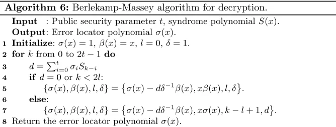
Our implementation follows the Berlekamp iterative algorithm as described in [16]. The algorithm begins with initializing polynomialsσ(x) = 1∈GF(2m)[x], β(x) =x∈GF(2m)[x], integersl= 0 andδ= 1∈GF(2m). The input syndrome polynomial is denoted as S(x) = P2i=1t−1Sixi ∈ GF(2m)[x]. Then within each iteration stepk(0≤k≤2t−1), the variables{σ(x), β(x), l, δ}are conditionally updated using operations described in Algorithm 6. Note that updating poly-nomial β(x) only involves multiplying a polynomial by x, which can be easily mapped to a binary shifting operation on its coefficients in hardware. Updat-ing integerl and field elementδonly involves subtraction/addition operations, and these operations can also be easily implemented in hardware. Therefore the bottleneck of the algorithm lies in computingdand updatingσ(x).
Algorithm 6: Berlekamp-Massey algorithm for decryption. Input : Public security parametert, syndrome polynomialS(x). Output: Error locator polynomialσ(x).
1 Initialize:σ(x) = 1,β(x) =x,l= 0,δ= 1. 2 forkfrom 0 to 2t−1do
3 d=Pt
i=0σiSk−i
4 if d= 0 ork <2l: 5 {σ(x), β(x), l, δ}=
σ(x)−dδ−1β(x), xβ(x), l, δ . 6 else:
7 {σ(x), β(x), l, δ}=
σ(x)−dδ−1β(x), xσ(x), k−l+ 1, d . 8 Return the error locator polynomialσ(x).
registerSvec= (0,0, ..., S0, S1, ..., Sk−1, Sk) for all 0≤k≤2t−1. Registerσvec is initialized as (0,0, ...,1) for the first iteration, and then gets updated with the new coefficients of σ(x) for the next iteration. Svec is initialized as all zeroes, and then constructed gradually by reading from a piece of memory which stores coefficientSiof syndrome polynomialS(x) at addressifor 0≤i≤2t−1. Within the k-th iteration, a read request for address k of the memory is issued. Once the corresponding coefficientSk is read out, it is inserted to the lowestmbits of
Svec. After the computation ofd, we start updating variables{σ(x), β(x), l, δ}.
To updateσ(x), one field-element inversion, one field-element multiplication, one scalar multiplication as well as one vector subtraction are needed. At first, field elementδ is inverted. As described in [28], the inversion of elements in GF(2m) can be implemented by use of a pre-computed lookup table. Each entry of the table can be read in one clock cycle. After reading outδ−1, a field-element multi-plication betweendandδ−1 is performed, which makes use of the GF(2m) mul-tiplication module as described in [28]. Once we getdδ−1, a scalar multiplication between field element dδ−1 and polynomialβ(x) starts, which can be mapped to an entry-wise vector multiplication between vector (dδ−1, dδ−1, ..., dδ−1) and (βt, βt−1, ..., β1, β0). The last step for updating σ(x) is to subtract dδ−1β(x) from σ(x). In a binary field GF(2m), subtraction and addition operations are equivalent. Therefore, the subtraction between σ(x) and dδ−1β(x) can simply be mapped to bit-wise xor operations between vector (σt, σt−1, ..., σ1, σ0) and vector (dδ−1β
t, dδ−1βt−1, ..., dδ−1β1, dδ−1β0). Updating polynomialβ(x) is done by conditionally replacing its coefficient registerβvec withδvec, and then shift the resulting value leftwards bym bits. Updating integer l and field element δ only involves simple and cheap hardware operations.
mulBM mulBM step Cycles Logic Time×Area Mem. Reg. Fmax
10 10 7379 6285 4.64·107 7 13,089 364 MHz
20 20 4523 7052 3.19·107 7 13,031 353 MHz
30 30 3571 7889 2.82·107 7 12,956 361 MHz
40 40 3095 9047 2.8·107 7 13,079 356 MHz
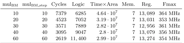
60 60 2619 11,400 2.99·107 7 13,274 354 MHz
Table 2: Performance of the Berlekamp-Massey module for m = 13, t = 119, and deg(S(x)) = 237.
We built a two-level design. The lower level is aBM stepmodule, which maps to one iteration, shown as “Berlekamp-Massey Step” in Figure 1. The higher-levelBMmodule then iteratively appliesBM stepandentry summodules. Table2 shows performance for the BM module. A time-area trade-off can be achieved by adjusting the design parameters mulBM and mulBM step, which are the number of multipliers used in the BMandBM stepmodules. mulBM and mulBM stepcan be freely chosen as integers between 1 andt+ 1.
3.3 Optimizations for Additive FFT
Evaluating a polynomial at multiple data points over GF(2m) is an essential step in both the key generation and the decryption processes. In key generation, an evaluation of the Goppa polynomial g(x) is needed for computing the par-ity check matrix H, while for decryption, it is required by the computation of the double-size parity check matrix H(2) as well as the evaluation of the error locator polynomial σ(x). Therefore, having an efficient polynomial-evaluation module is very important for ensuring the performance of the overall design. We use a characteristic-2 additive FFT algorithm introduced in 2010 by Gao and Mateer [12], which was used for multipoint polynomial evaluation by Bernstein et al. in 2013 [5]. Additive FFT consists of two parts. First, radix conversion and twist is performed on the input polynomial. Given a polynomialg(x) of 2k coef-ficients, the recursive twist-then-radix-conversion process returns 2k 1-coefficient polynomials. Then, these 1-coefficient polynomials are used to iteratively evalu-ate the input points by use of the reduction process.
We applied some modifications and improvements to both parts of the addi-tive FFT design from [28]:
Design Coeffs. Mult. Cycles Logic Time×Area Reg. Mem. Fmax
Our 120 2 385 1893 7.3·105 3541 6 305 MHz
Our 120 4 205 2679 5.5·105 3622 10 273 MHz
[28] 128 4 211 5702 1.2·106 7752 0 407 MHz
Our 120 8 115 4302 4.9·105 3633 17 279 MHz
[28] 128 8 115 5916 6.8·105 7717 0 400 MHz
Table 3: Performance of our radix-conversion module compared to [28] for GF(213).
The radix-conversion module in [28] is using dedicated logic for each round for summing up the required coefficients, computing all coefficients within one cycle. Computing all coefficients with dedicated logic for each round requires a significant amount of area although radix conversion only requires a very small amount of cycles compared to the overall additive FFT process. Therefore, this results in a relatively high time-area product and a poor usage of resources.
We improve the area-time product at the cost of additional cycles and ad-ditional memory requirements by using the same logic block for different coef-ficients and rounds. An additional code-generation parameter is used to specify how many coefficients should be computed in parallel, which equals to the num-ber of multipliers (1≤Mult.≤t+ 1) used in twist when mapping to hardware implementations. Each round then requires several cycles depending on the se-lected parameter. The computation of the new coefficients requires to sum up some of the previous coefficients. The logic therefore must be able to add up any selection of coefficients depending on the target coefficient. We are using round-and coefficient-dependent masks to define which coefficients to sum up in each specific case. These masks are stored in additional RAM modules.
Furthermore, in the design of [28], the length of the input polynomial is constrained to be a power of 2. For shorter polynomials, zero-coefficients need to be added, which brings quite some logic overhead especially on some extreme cases. For example, for a polynomial of 129 coefficients (t= 128), a size-256 radix conversion module will be needed. Instead, our improved design eliminates this constraint and allows an arbitrary input length with low overhead and therefore is able to further reduce cycle count and area requirements.
Mult. Cycles Logic Time×Area Mem. Bits Mem. Reg. Fmax
32 968 4707 4.56·106 212,160 63 10,851 421 MHz 64 488 9814 4.79·106 212,992 126 22,128 395 MHz
Table 4: Performance of our parameterized size-128 reduction module for GF(213).
the output of the last radix-conversion round. The data memory D within the reduction module is configured as follows: The depth of the memory equals to 2k, based on this, the width of the memory is determined asm×2m−k since in totalm×2mmemory bits are needed to store the evaluation results for all the elements in GF(2m). Each row of memoryDis initialized with 2m−k identical 1-coefficient polynomials. The other piece of memory within the reduction module is the constants memory C. It has the same configuration as the data memory and it stores all the elements for evaluation of different reduction rounds. Once the initialization of data memory and constants memory is finished, the actual computation starts, which consists of the same amount of rounds as needed in the radix conversion process. Within each round, two rows of values (f0andf1) are read from the data memory and the corresponding evaluation points from the constants memory, processed, and then the results are written back to the data memory. Each round of the reduction takes 2kcycles to finish. In total, the reduction process takesk×2k cycles plus overhead for memory initialization.
In our current design, we made the reduction module parameterized by in-troducing a flexible memory configuration. The width of memoriesDand Ccan be adjusted to achieve a trade-off between logic and cycles. The algorithmic pat-tern for reduction remains the same, while the computational patpat-tern changes due to the flexible data reorganization within the memories. Instead of fixing the memory width as m×2m−k, it can be configured as a wider memory of width m×2m−k+i,0 ≤ i ≤k. In this way, we can store multiple 1-coefficient polynomials at one memory address. The organization of the constants mem-ory needs to be adapted accordingly. Therefore, within each cycle, we can either fetch, do computation on, or write back more data and therefore finish the whole reduction process within much fewer cycles (k×2k−i plus overhead of few ini-tialization cycles). However, the speedup of the running time is achieved at the price of increasing the logic overhead, e.g., each time the width of the memory doubles, the number of multipliers needed for computation also doubles.
Table4 shows the performance of our parameterized reduction module. We can see that doubling the memory width halves the cycles needed for the reduc-tion process, but at the same time approximately doubles the logic utilizareduc-tion. We can see that although the memory bits needed for reduction remain similar for different design configurations, the number of required memory blocks dou-bles in order to achieve the increased memory width. Users can easily achieve a trade-off between performance and logic by tuning the memory configurations within the reduction module.
Multipliers
Design Rad. Red. Cycles Logic Time×Area Mem. Reg. Fmax
Our 4 32 1173 7344 8.61·106 73 14,092 274 MHz [28] 4 32 1179 10,430 1.23·107 63 18,413 382 MHz
Our 8 64 603 13,950 8.41·106 143 25,603 279 MHz [28] 8 32 1083 10,710 1.16·107 63 18,363 362 MHz
Table 5: Performance of our optimized additive-FFT module compared to [28] for
m= 13, deg(g(x)) = 119. Rad. and Red. are the number of multipliers used in radix conversion and twist (reduction) separately.
we are able to achieve a 28% smaller time-area product compared to [28] when Rad. = 4 and Red. = 64.
4
Key Generation, Encryption and Decryption
We designed the Niederreiter cryptosystem by using the main building blocks shown in Figure2. Note that we are using two simple 64-bit Xorshift PRNGs in our design to enable deterministic testing. For real deployment, these PRNGs must be replaced with a cryptographically secure random-number generator, e.g., [8]. We require at most brandom bits per clock cycle per PRNG.
4.1 Key Generation
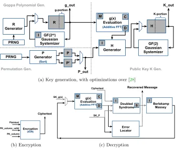
The overall design of our key-generation module is identical to the design in [28]. The dataflow diagram is shown in Figure 2a. However, we improve the security of private-key generation by substituting the Fisher-Yates Shuffle module with a merge-sort module in order to generate a uniform and random permutation in constant time (see Section3.1). The generation of the public key is improved by several optimizations applied to the additive FFT module (see Section3.3).
Table 6 shows a comparison of the performance of the old implementation in [28] with our new, improved implementation. Despite the higher cost for the constant-time permutation module, overall, we achieve an improvement in regard to area requirements and therefore to the time-area product at roughly the same frequency on the price of a higher memory demand. However, the overall memory increase is less than 10% which we believe is justified by the increased side-channel resistance due to the use of a constant-time permutation.
4.2 Encryption
Figure 2b shows the interface of the encryption module. The encryption mod-ule assumes that the public key K is fed in column by column. The matrix-vector multiplication [Imt|K]×e is mapped to serial xor operations. Once
H R
R Generator
PRNG
GF(2m)
Gaussian Systemizer g-portion g(x) Evaluation (Additive FFT) H Generator g_out P Generator (Sort) P P_out GF(2) Gaussian Systemizer K_out PRNG Permutation Gen. Goppa Polynomial Gen.
Public Key K Gen.
K-portion C D P' I I M
(a) Key generation, with optimizations over [28]
(b) Encryption
g(x) Evaluation (Additive FFT)
C
D SyndromeDoubled
SK_g(x) SK_P Berlekamp Massey Error Locator
Ciphertext Recovered Message
I I
M
(c) Decryption
Fig. 2: Dataflow diagrams of the three parts of the full cryptosystem: (a) key generation, (b) encryption, and (c) decryption. Dark gray boxes represent block memories, while white boxes represent major logic modules.
(PK column) is available at the input port, the module checks if the
correspond-ing bit of plaintexteis 1 or 0. If the bit value is 1, then anxoroperation between the current output register (initialized as 0) and the new public-key column is carried out. Otherwise, no operation is performed. After thexoroperation be-tween K and the last (n−mt) bits ofeis finished, we carry out one morexor
operation between the output register and the first mtbits of e. Then the up-dated value of the output register will be sent out as the cipheretxt c. Table7 shows performance of the encryption module. The encryption module is able to handle one column of the public key in each cycle and therefore requires a fixed number of (n−mt) cycles independent of the secret input vectore.
4.3 Decryption
comput-Case NH NR Cycles Logic Time×Area Mem. Fmax Time
Prior work [28]
logic 40 1 11,121,220 29,711 3.30·1011 756 240 MHz 46.43 ms bal. 80 2 3,062,942 48,354 1.48·1011 764 248 MHz 12.37 ms time 160 4 896,052 101,508 9.10·1010 803 244 MHz 3.68 ms
Our work
logic 40 1 11,121,214 22,716 2.53·1011 819 237 MHz 46.83 ms bal. 80 2 3,062,936 39,122 1.20·1011 827 230 MHz 13.34 ms time. 160 4 966,400 88,715 8.57·1010 873 251 MHz 3.85 ms
Table 6: Performance of the key-generation module for parametersm= 13, t= 119, and n = 6960. All the numbers in the table come from compilation reports of the Altera tool chain for Stratix V FPGAs.
m t n Cycles Logic Time×Area Mem. Reg. Fmax
13 119 6960 5413 4276 2.31·107 0 6977 448 MHz
Table 7: Performance for the encryption module.
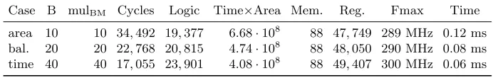
ing the double-size syndrome S(2), we combine these two steps together. The computation ofS(2) can be mapped to serial conditional xoroperations of the columns ofH(2). Based on the observation that the last (n−mt) bits of vector (c|0) are all zero, the last (n−mt) columns of H(2) do not need to be com-puted. Furthermore, the ciphertextc should be a uniformly random bit string. Therefore, for the first mt columns ofH(2), roughly only half of the columns need to be computed. Finally, we selectively choose which columns of H(2) we need to compute based on the nonzero bits of the binary vector (c|0). In total, approximatelym×t2field element multiplications are needed for computing the double-size syndrome. The computation of the corresponding columns ofH(2) is performed in a similar column-block-wise method as described in [28]. The size B (1≤B≤ mt
Case B mulBM Cycles Logic Time×Area Mem. Reg. Fmax Time
area 10 10 34,492 19,377 6.68·108 88 47,749 289 MHz 0.12 ms bal. 20 20 22,768 20,815 4.74·108 88 48,050 290 MHz 0.08 ms time 40 40 17,055 23,901 4.08·108 88 49,407 300 MHz 0.06 ms
Table 8: Performance for the decryption module form = 13, t = 119 and n= 6960, mulBM stepis set to mulBM.
5
Testing, Evaluation, and Comparison
Our implementation of the Niederreiter cryptosystem is fully parameterized and can be synthesized for any choice of reasonable security parameters. However, the main target of our implementation is the 256-bit (classical) security level, which corresponds to a level at least “128-bit post-quantum security”. For testing, we used the parameters suggested in the PQCRYPTO recommendations [2]: m= 13,t= 119,n= 6960 andk= 5413 (k=n−mt).
Testing.To validate the FPGA implementation, in addition to simulations, we implemented a serial IO interface for communication between the host computer and the FPGA. The interface allows us to send data and simple commands from the host to the FPGA and receive data, e.g., public and private key, ciphertext, and plaintext, from the FPGA. We verified the correct operation of our design by comparing the FPGA outputs with our Sage reference implementation (using the same PRNG and random seeds).
Evaluation. We synthesized our design using Altera Quartus 17.0 for these parameters on a Stratix V FPGA (5SGXEA7N). The results are given in Table9, with included logic overhead of the IO interface. We provide numbers for three performance parameter sets, one for small area, one for small runtime, and one for balanced time and area. The parameters NR and NH control the size of the systolic array in the Gaussian systemizer modules, which are used for computing the private Goppa polynomial and the public key. Parameter B is the matrix-block size used for computing the syndrome. Parameter mulBM determines the number of multipliers used in the high-level BMdecoding module. The number of multipliers (mulBM step) used in the low-levelBM stepmodule is set to mulBM for the evaluation. The memory requirement varies slightly due the differences in the memory word size based on the design parameters. These design parameters can be freely chosen as long as the synthesized result fits on the target FPGA. For security parameter set m = 13, t = 119, n = 6960, our experiment shows that the largest design parameter set we can fit on Stratix V FPGA is: NR = 250, NH= 6, mulBM = 60, mulBM step = 60, and B = 60.
Case NH NR B mulBM Logic Mem. Reg. Fmax
area 40 1 10 10 53,447 (23%) 907 (35%) 118,243 245 MHz bal. 80 2 20 20 70,478 (30%) 915 (36%) 146,648 251 MHz time 160 4 40 40 121,806 (52%) 961 (38%) 223,232 248 MHz
Table 9: Performance for the entire Niederreiter cryptosystem (i.e., key generation, encryption, and decryption) including the serial IO interface when synthesized for the Stratix V (5SGXEA7N) FPGA; mulBM stepis set to mulBM.
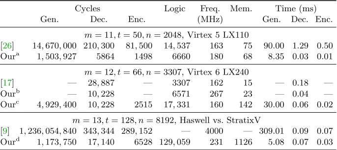
Cycles Logic Freq. Mem. Time (ms)
Gen. Dec. Enc. (MHz) Gen. Dec. Enc.
m= 11, t= 50, n= 2048, Virtex 5 LX110
[26] 14,670,000 210,300 81,500 14,537 163 75 90.00 1.29 0.50 Oura 1,503,927 5864 1498 6660 180 68 8.35 0.03 0.01
m= 12, t= 66, n= 3307, Virtex 6 LX240
[17] — 28,887 — 3307 162 15 — 0.18 —
Ourb — 10,228 — 6571 267 23 — 0.04 —
Ourc 4,929,400 10,228 2515 17,331 160 142 30.00 0.06 0.02
m= 13, t= 128, n= 8192, Haswell vs. StratixV
[9] 1,236,054,840 343,344 289,152 — 4000 — 309.01 0.09 0.07 Ourd 1,173,750 17,140 6528 129,059 231 1126 5.08 0.07 0.03
Table 10: Comparison with related work. Logic is given in “Slices” for Xilinx Virtex FPGAs and in “ALMs” for Altera Stratix FPGAs.
a(N
H, NR, B, mulBM, mulBM step) = (20, 2, 20, 20, 20), entire Niederreiter cryptosystem. b(B, mul
BM, mulBM step) = (20, 20, 20), decryption module. c(N
H, NR, B, mulBM, mulBM step) = (20, 2, 20, 20, 20), entire Niederreiter cryptosystem. d(NH, NR, B, mulBM, mulBM step) = (160, 4, 80, 65, 65), entire Niederreiter cryptosystem.
with the Xilinx tool-chain version 14.7 for a Virtex-5 XC5VLX110 FPGA. Note that the performance data of [26] in Table 10 includes a CCA2 conversion for encryption and decryption, which adds some overhead compared to our design. From Table10, we can see that our design is much faster when comparing cycles and time, and also much cheaper in regard to area and memory consumption.
secu-rity parameter set m = 12, t = 66, n = 3307 when synthesized for a Virtex 6 XC6VLX240T FPGA.
Finally, we also compare the performance of our hardware design with the to-date fastest CPU implementation of the Niederreiter cryptosystem [9]. In this case, we ran our implementation on our Altera Stratix V FPGA and compare it to a Haswell CPU running at 4 GHz. Our implementation competes very well with the CPU implementation, despite the over 10x slower clock of the FPGA.
6
Conclusion
This paper presented a complete hardware implementation of Niederreiters’s code-based cryptosystem based on binary Goppa codes, including key genera-tion, encryption and decryption. The presented design can be configured with tunable parameters, and uses code-generation to generate vendor-neutral Ver-ilog HDL code for any set of reasonable parameters. This work presented hard-ware implementations of an optimization of the Gao-Mateer additive FFT for polynomial evaluation, of merge sort used for obtaining uniformly distributed permutations, and of a constant-time Berlekamp-Massey algorithm.
Open-Source Code. The source code for this project is available under an open-source license athttp://caslab.csl.yale.edu/code/niederreiter/. Acknowledgments. This work was supported in part by United States’ Na-tional Science Foundation grant 1716541. We would like to acknowledge FPGA hardware donations form Altera (now part of Intel). We also want to thank Tung (Tony) Chou for his invaluable help. This paper has been greatly im-proved thanks to feedback from our shepherds Lajla Batina and Pedro Maat Costa Massolino and the anonymous reviewers.
References
1. Alkadri, N.A., Buchmann, J., Bansarkhani, R.E., Kr¨amer, J.: A framework to se-lect parameters for lattice-based cryptography. Cryptology ePrint Archive, Report 2017/615 (2017),https://eprint.iacr.org/2017/615
2. Augot, D., Batina, L., Bernstein, D.J., Bos, J., Buchmann, J., Castryck, W., Dunkelman, O., G¨uneysu, T., Gueron, S., H¨ulsing, A., Lange, T., Mo-hamed, M.S.E., Rechberger, C., Schwabe, P., Sendrier, N., Vercauteren, F., Yang, B.Y.: Initial recommendations of long-term secure post-quantum systems. Tech. rep., PQCRYPTO ICT-645622 (2015), https://pqcrypto.eu.org/docs/ initial-recommendations.pdf.
3. Avanzi, R., Hoerder, S., Page, D., Tunstall, M.: Side-channel attacks on the McEliece and Niederreiter public-key cryptosystems. JCEN 1(4), 271–281 (2011) 4. Bernstein, D.J., Buchmann, J., Dahmen, E. (eds.): Post-Quantum Cryptography.
Springer, Heidelberg (2009)
6. Bernstein, D.J., Lange, T., Peters, C.: Attacking and defending the McEliece cryp-tosystem. In: Buchmann, J., Ding, J. (eds.) PQCrypto 2008. LNCS, vol. 5299, pp. 31–46. Springer, Heidelberg (2008)
7. Chen, L., Moody, D., Liu, Y.K.: NIST post-quantum cryptography standard-ization, https://csrc.nist.gov/projects/post-quantum-cryptography/post-quantum-cryptography-standardization/.
8. Cherkaoui, A., Fischer, V., Fesquet, L., Aubert, A.: A very high speed true random number generator with entropy assessment. In: Bertoni, G., Coron, J.S. (eds.) CHES 2013. LNCS, vol. 8086, pp. 179–196. Springer, Heidelberg (2013)
9. Chou, T.: McBits revisited. In: Fischer, W., Homma, N. (eds.) CHES 2017. LNCS, vol. 10529, pp. 213–231. Springer, Heidelberg (2017)
10. DasGupta, A.: The matching, birthday and the strong birthday problem: a con-temporary review. J. Stat. Plan. Inference 130(1), 377–389 (2005)
11. Fisher, R.A., Yates, F.: Statistical tables for biological, agricultural and medical research. Oliver and Boyd (1948)
12. Gao, S., Mateer, T.: Additive fast Fourier transforms over finite fields. IEEE Trans-actions on Information Theory 56(12), 6265–6272 (2010)
13. Guo, Q., Johansson, T., Stankovski, P.: A key recovery attack on MDPC with CCA security using decoding errors. In: Cheon, J.H., Takagi, T. (eds.) ASIACRYPT 2016. LNCS, vol. 10031, pp. 789–815. Springer, Heidelberg (2016)
14. Heyse, S., G¨uneysu, T.: Code-based cryptography on reconfigurable hardware: tweaking Niederreiter encryption for performance. JCEN 3(1), 29–43 (2013) 15. Li, Y.X., Deng, R.H., Wang, X.M.: On the equivalence of McEliece’s and
Niederre-iter’s public-key cryptosystems. IEEE Transactions on Information Theory 40(1), 271–273 (1994)
16. Massey, J.: Shift-register synthesis and BCH decoding. IEEE transactions on In-formation Theory 15(1), 122–127 (1969)
17. Massolino, P.M.C., Barreto, P.S.L.M., Ruggiero, W.V.: Optimized and scalable co-processor for McEliece with binary Goppa codes. ACM Transactions on Embedded Computing Systems 14(3), 45 (2015)
18. McEliece, R.J.: A public-key cryptosystem based on algebraic coding theory. DSN Progress Report 42–44, 114—116 (1978)
19. Niederreiter, H.: Knapsack-type cryptosystems and algebraic coding theory. Prob-lems of Control and Information Theory 15, 19–34 (1986)
20. Patterson, N.: The algebraic decoding of Goppa codes. IEEE Transactions on In-formation Theory 21(2), 203–207 (1975)
21. Post-quantum cryptography for long-term security, PQCRYPTO, ICT-645622, https://pqcrypto.eu.org/.
22. Rostovtsev, A., Stolbunov, A.: Public-key cryptosystem based on isogenies. Cryp-tology ePrint Archive, Report 2006/145 (2006)
23. Shor, P.W.: Algorithms for quantum computation: Discrete logarithms and factor-ing. In: Foundations of Computer Science – FOCS ’94. pp. 124–134. IEEE (1994) 24. Shor, P.W.: Polynomial-time algorithms for prime factorization and discrete
loga-rithms on a quantum computer. SIAM review 41(2), 303–332 (1999)
25. Shoufan, A., Strenzke, F., Molter, H.G., St¨ottinger, M.: A timing attack against Patterson Algorithm in the McEliece PKC. In: ICISC. vol. 5984, pp. 161–175. Springer, Heidelberg (2009)
27. Sidelnikov, V.M., Shestakov, S.O.: On insecurity of cryptosystems based on gen-eralized Reed-Solomon codes. Discrete Math. Appl. 2(4), 439–444 (1992)

![Table 3: Performance of our radix-conversion module compared to [28] for GF(213).](https://thumb-us.123doks.com/thumbv2/123dok_us/7956703.1320143/13.612.150.469.128.204/table-performance-radix-conversion-module-compared-gf.webp)
![Table 5: Performance of our optimized additive-FFT module compared to [28] form = 13, deg(g(x)) = 119](https://thumb-us.123doks.com/thumbv2/123dok_us/7956703.1320143/15.612.149.465.117.199/table-performance-optimized-additive-fft-module-compared-form.webp)