SoC it to EM: electromagnetic side-channel
attacks on a complex system-on-chip
J. Longo1, E. De Mulder2, D. Page1, and M. Tunstall2
1
Department of Computer Science, University of Bristol, Merchant Venturers Building, Woodland Road,
Bristol, BS8 1UB, United Kingdom.
{jake.longo,daniel.page}@bristol.ac.uk 2
Rambus Cryptography Research Division, 425 Market Street, 11th Floor, San Francisco, CA 94105, United States.
{elke.demulder,michael.tunstall}@cryptography.com
Abstract. Increased complexity in modern embedded systems has
pre-sented various important challenges with regard to side-channel attacks. In particular, it is common to deploy SoC-based target devices with high clock frequencies in security-critical scenarios; understanding how such features align with techniques more often deployed against simpler de-vices is vital from both destructive (i.e., attack) and constructive (i.e., evaluation and/or countermeasure) perspectives. In this paper, we in-vestigate electromagnetic-based leakage from three different means of executing cryptographic workloads (including the general purpose ARM core, an on-chip co-processor, and the NEON core) on the AM335x SoC.
Our conclusion is that addressing challenges of the type aboveisfeasible,
and that key recovery attacks can be conducted with modest resources.
Keywords: side-channel, electromagnetic, system on chip, ARM, NEON.
1
Introduction
A significant proportion of academic literature on side-channel attacks already
side-channel attacks are a threat. For example, smart-phones now house multi-core, System-on-Chip (SoC) components with multi-gigahertz clock frequencies as standard, and, modulo constraints such as energy efficiency, market forces will drive increased use of similar components over time.
Within this context, use of ElectroMagnetic (EM) side-channel leakage is particularly attractive. Rohatgi [38] offers a comprehensive overview of both the physical phenomenon itself plus seminal results such as [3,21,37], neither of which we expand on unless specifically relevant. Versus power analysis [29], the non-contact, spatially flexible nature of an EM-based alternative means it a) represents a less invasive means of taking acquisitions, b) avoids issues such as on-chip voltage regulation and, most importantly, c) permits targeting of specific regions of (or components on) an SoC that otherwise offer composite leakage.
Our goal in this paper is to demonstrate that by carefully translating and refining existing techniques, EM-based side-channel attacks are viable against modern, complex targets. The challenges of evaluation and countermeasure in-strumentation already motivate such work, but are arguably magnified by other constructive applications of side-channels (e.g., protection of intellectual prop-erty [7] and Trojan hardware detection [19]) relevant to SoCs: allbenefit from better,open (noting this topic seems to represent an active but largely undoc-umented focus of various security services [40]) understanding of the associated leakage characteristics. We explore a single exemplar target device, namely the Texas Instruments (TI) AM335x SoC on a BeagleBone Black development board, with respect to three options for execution of cryptographic workloads. Following the relevant background material in Section 2, our contribution is, concretely, the EM-based analysis of
1. AES executed by an OpenSSL server on the ARM core (Section 3), 2. the proprietary AES co-processor (Section 4), and
3. the NEON3 core, including bit-sliced AES (Section 5).
A central conclusion is that, while some effort is required to characterise the leakage, attack complexity does notnecessarilyscale in line with perceived device complexity. For example, in the first case above we are able to acquire and exploit leakage at much lower frequencies than suggested by the 1 GHz system clock; this implies attack cost may also be lower than expected, and hence relying on device complexity (resp. obscurity) to provide security is dubious at best.
2
Background
2.1 An overview of the BeagleBone platform
BeagleBone Black is a single-board computer built around a AM335x “Sitara” SoC. Constituent components can be grouped logically into four sub-systems
3 Note that by targeting NEON, we specifically aim to add detail to the premise
introduced during the CHES 2014 rump session talk of Bernstein and Lange: see
Integer core NEON core
L1 I-cache L1 D-cache
L2 cache
OCP bridge 176 kB
ROM
64 kB RAM
OCP-based L3/L4 NoC interconnect PowerVR GPU
Cryptographic co-processor
64 kB RAM
Display controller
Network controller
UART
SPI
I2
C
USB
. . .
DMA
RTC
WDT
JTAG
. . .
DDR-based memory interface
Fig. 1: A block diagram of the AM335x SoC, replicating [26, Figure 1-1]; note that components and sub-systems pertinent to sections in the paper are highlighted.
per [26, Figure 1-1] (which is reproduced in Figure 1 for the sake of complete-ness); the sub-systems are able to communicate via a dedicated Network-on-Chip (NoC), or interconnect. The following sections focus on the Micro-Processor Unit (MPU) and the cryptographic co-processor. Although the latter lacks public doc-umentation of the internal design (bar device driver source code4 that interfaces with it), the former warrants further analysis: we refer to the extensive liter-ature5 for in-depth coverage. In short, however, alongside L1 and L2 caches and on-chip memory, the central 32-bit ARM Cortex-A8 MPU core is clocked up to 1 GHz. As they dominate cryptographic use-cases, we focus on the ex-ecution of integer instructions by this core, which has two distinct pipelines: the 13-stage ARM pipeline (or core) and 10-stage NEON pipeline (or core), es-sentially a SIMD co-processor marketed as an accelerator for multimedia and signal processing workloads. Within the ARM pipeline, the 6 execution stages are supported by two symmetric integer pipelines, a multiplier pipeline and a load/store pipeline; operands are supplied from a 16-entry register file of 32-bit registers. Within the NEON pipeline, the 6 execution stages are supported by integer ALU, Multiply-ACcumulate (MAC) and load-store pipelines; operands are supplied from a 256-byte register file, which can be viewed as comprising 32 double-word (64-bit) or 16 quad-word (128-bit) entries (each with sub-words of
w∈ {8,16,32,64,128} bits) depending on the instruction type. Both pipelines are dual-issue (meaning 2 instructions can be issued per cycle, modulo depen-dencies), and in-order (meaning instructions complete in the same order they were issued). Instructions enter the NEON pipeline after having been decoded by the ARM pipeline, with the two decoupled using a 16-entry queue.
4
http://github.com/torvalds/linux/blob/master/drivers/crypto/omap-aes.c 5
The central point to take away from such analysis is the high degree of architectural complexity evident, even ignoring the number of components. For example, the MPU alone has a total of 3 clock and 4 power domains. Such features make the SoC an extremely challenging target with respect to Signal-to-Noise Ratio (SNR), and underlines the advantages offered by EM-based leakage.
2.2 Experimental environment
Acquisition and measurement equipment. To allow reproducibility, the
equip-ment used throughout this paper is listed below:
– Tektronix DPO7104 1 GHz oscilloscope, – Signatec PX14400 400 MS/s digitiser,
– Langer PA303 pre-amplifier plus various (e.g., low-pass) hardware filters, – Langer RF-3 mini near-field probe set,
– Langer ICS105 IC scanner (or XY-table), – Matlab 2014b (with signal processing toolbox).
The configuration was therefore very standard: the target device was mounted on the XY-table to allow micro-positioning of the probe(s), which supplied an amplified, filtered signal to either the digitiser (Section 3 and Section 5) or oscilloscope (Section 4, to cope with a higher sampling rate). This limits our remit strictly to close-range acquisitions, rather than at a distance, e.g., per [43].
Software stack. We used a standard BeagleBone Black distribution of Debian
“Wheezy” on the target device (Linux kernel version 3.13.3). The device was booted from on-board embedded MultiMediaCard (eMMC) storage as is; no standard system processes were disabled. On top of this platform we use OpenSSL 1.0.1j, with thecryptodevextension6 enabled when appropriate.
2.3 Leakage detection and exploitation strategy
Notation. For some set or sequence x of lengthn, we let x[j] denote the j-th
element ofxsuch that 0≤j < n;xi then denotes thei-th such object within a
larger collection, with the subscript omitted where irrelevant. We useH(x) and
D(x, y) to denote the Hamming weight and distance, respectively, of somexand
y. As such,
ri=DUTfk(xi) λi
models somei-th execution of an operationfon the target deviceDUT, involving a security critical datumk (e.g., key material), accepting inputxi and yielding
an output ri and an EM-based trace of leakage λi (a sequence of samples).
Depending on the context, the target operation ranges from single instructions to entire algorithms (e.g., AES), and, from the attacker perspective, ri and/or xi may be known or unknown and controlled or uncontrolled.
6
λis essentially a function of the target device (or leakage model), the opera-tionf and inputxi,plusthe probe type and location (and any other parameters
of the experimental environment). With this in mind, mounting a concrete attack demands an attacker a) determines when and where (in time and/or frequency domains)λcontains useful, exploitable leakage, and b) selects a probe configu-ration to maximise said leakage (i.e., maximise the SNR).
Leakage detection. While several strategies, e.g., [11,12,23], have been proposed
to address the former challenge above, throughout this paper we use Welch’s t-test. More specifically, we use the Test Vector Leakage Assessment (TVLA) methodology of Goodwill et al. [23]. Although there are several varients (fixed-versus-random and semi-fixed-(fixed-versus-random for instance), the basic idea in-volves constructing two sets of test vectors V0 and V1: the former contains a single (semi-)fixed vector, whereas the latter contains (a large number of) vec-tors chosen uniformly at random. Note that Uno et al.[42, Section II.A] use a special-case of this approach, with fixed and random test vectors replaced by full- and zero-weight alternatives (the assumed maximum and minimum cases of leakage under a Hamming weight model). For eachi-th invocation of the target device, the input is selected by first randomly selecting a test vector type, i.e.,
a b ← {$ 0,1}, then a test vector from the appropriate set, i.e., an xi
$
←Vb; the
resulting trace of leakage,λi, is added to a setΛb based on the test vector type.
Then, we compute the t-statistic trace as
t=
¯
Λ0−Λ¯1
q σ2
0
|Λ0|+ σ2
1
|Λ1|
where |Λb|, ¯Λb and σb2 respectively denote the sample size, sample mean and
sample variance of set Λb. The idea is that given a threshold τ (say τ = 4.5
per [23, Section 3]), if we find |t[j]| > τ then we claim significant leakage is detected at thej-th sample: at that point there is a statistically observable dif-ference between fixed and random test vectors, so there may be data-dependent and thus potentially exploitable information present. Each following section uses this approach: section-specific detail is included where appropriate, with a com-prehensive overview deferred to Appendix A.
3
Software-based AES
ARM and NEON region
SRAM region
ARM and NEON region SRAM
region
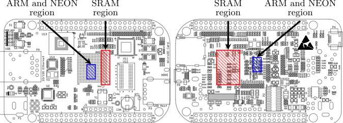
Fig. 2: BeagleBone Black schematic (source: http://github.com/CircuitCo/ BeagleBone-Black/blob/rev_a5c/BBB_PCB.zip) from front-side (left) and back-side (right), annotated with probe locations for leakage from the SRAM (red) and ARM and NEON cores (blue).
and Windows XP (on x86), Aboulkassimi et al. [1,2] who mount differential EM-based attacks on AES executing under Java ME (on ARM), and Pellegrini et al. [35] who mount voltage depletion fault attacks on RSA executing under Linux (on SPARC).
In this section we consider a systems-oriented scenario of the latter type. Specifically, we imagine the target is a communications device (e.g., a smart-phone) engaged in a TLS-based session with some server. As such, the attacker can observe computation of
ci=DUTAES-128-CBCk (mi) λi.
That is, AES-128 encryption, in CBC mode, of some unknown plaintext mi
under k to yield a known ciphertext ci (since it is communicated across the
network). Concretely, each encryption operation is performed by OpenSSL in software via the default T-tables-based [14, Section 4.2] implementation.
3.1 Experimental outline
Before considering an attack strategy to exploit λand recoverk, a host of ex-perimental challenges need to be addressed: the first relates to acquisition ofλ. In common with analysis of other unknown/as yet unprofiled target devices, we rely on initial exploration based on full control of a replica profiling device. We stress that our use of the profiling device is simply to give insight into the asso-ciated signal characteristics: although it is well known that such an approach is not necessarily sufficient for building templates [13], we simply use it to mitigate systemic features (e.g., of the OS scheduler, hardware and software interrupts etc.) inherent in the scenario above.
Probe location. An initial, manual scan of the SoC surface was conducted in
0 1000 2000 3000 4000 5000
Sample Index
Amplitude
(a) Uninterrupted.
0 1000 2000 3000 4000 5000
Sample Index
Amplitude
(b) Interrupted.
Fig. 3: Impact of interrupts on the acquisition process in Section 3: whereas the uninterrupted case (left) yields a “clean” trace, the interrupted case (right) is corrupted (during the annotated period).
0 100 200 300 400 500
Sample Index
Amplitude
(a) 300 MHz.
0 50 100 150 200 250
Sample Index
Amplitude
(b) 600 MHz.
0 50 100 150 200
Sample Index
Amplitude
(c) 800 MHz.
0 20 40 60 80 100 120 140 160
Sample Index
Amplitude
(d) 1 GHz.
Fig. 4: Impact of clock scaling on the acquisition process in Section 3: each trace represents execution of AES under one of the four available clock frequencies.
0
10
20
30
40
50
60
70
80
Time (ms)
0
200
400
600
800
1000
1200
F
requency
(MHz)
−
70
−
65
−
60
−
55
−
50
−
45
−
40
−
35
−
30
Power
(db)
0 50 100 150 200 250
Sample Index
−100
−50
0 50 100
t-statistic
(a) Fixed-versus-random test.
0 10 20 30 40 50 60 70 80
Number of Traces (×1000)
−0.3
−0.2
−0.1 0.0 0.1 0.2 0.3
Correlation
(b) Single-bit correlation.
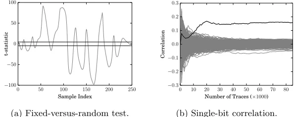
Fig. 6: Leakage analysis results for a free-running target using 85,000 sub-traces matched at 600 MHz. The leakage detection test (left) shows leakage above the significance threshold τ = 4.5 (marked in black on the Y-axis) throughout the AES execution. The single-bit analysis (right) tracks the correct key bit hypoth-esis of the first byte over the number of sub-traces used.
intensive operations (namely AES encryption, as performed by OpenSSL). By periodically cycling through the kernels and monitoring the frequency response (illustrated by Figure 5), two distinct regions of interest were identified (shown in Figure 2). We attribute one region (straddling the SoC edge and SRAM bus) to the memory intensive kernel, and hence memory access. Given that the memory bus is specific to this development kit, that no effort appears to have been made to secure it, and that a complete operational datasheet is available7, we did not feel it warranted further investigation even though it will likely yield exploitable leakage. The second region is located centrally on the AM335x surface, over a cluster of capacitors on the back-side of the board (specifically, around C94 and C46). Motivated by a) the magnitude of the frequency response observed during the AES execution, but also b) the long-term trend toward stacked fabrication processes (and associated decrease in SNR), we fixed the probe location over this support circuitry.
Acquisition tuning. The leakage from the selected region was identifiable using
relatively low frequencies alone, i.e., below 100 MHz. We expect this, to some degree, since a) AES throughout is clearly lower than the system clock frequency (one round is requires more than one instruction), and b) the on-chip discrete components coupled with the capacitor behave as a low-pass filter. As such, we applied a band-pass filter to the amplified signal centred on 45 MHz with a bandwidth of 24 MHz. This is interesting in so far as it allows use of less capable, and hence less expensive acquisition equipment. That is, rather than use a high-specification oscilloscope, we were able to use a lower-specification digitiser.
Bulk, or multi-block acquisitions. Our next step was to replace the artificial
ker-nels with a “free-running” uninstrumented OpenSSL client instance: no artificial
7
(e.g., hardware, via a GPIO pin) triggers are inserted. A coarse, soft trigger is attractive, but strictly to limit acquisitions to a target session (i.e., onek) rather than to provide alignment per se: each trace λi acquired therefore relates tol
invocations of AES rather than 1, i.e., each ci is now a (16·l)-byte or l-block
ciphertext, as generated by the TLS record layer. Such a soft trigger is easily realised via traffic analysis, and is additionally beneficial since it permits ci to
be known (i.e., sniffed) rather than controlled (i.e., injected) by the attacker. Although we argue that this choice is more realistic than the alternative, it has both positive and negative effects. On one hand, bulk acquisition significantly reduces the wall-clock time required [6, Section 3] and allows the effect of data and instruction caches to be largely ignored (since all but the first few AES invocations will occur with a warm cache). On the other, we must address various challenges relating to systematic noise that occurs over the longer time period (and which for “one-shot” devices such as smart-cards, are normally irrelevant).
Interrupt detection and synchronisation. The OS may preempt a user process if
it does not voluntarily yield, or if the kernel needs to service an interrupt: use of bulk acquisition necessitates we account for these interrupts, because they will be observed more frequently during the computation of longer ciphertexts.
Figure 3 demonstrates that an uninterrupted versus interrupted trace can be identified visually. Weautomatesimilar identification using the trace alignment scores (i.e., a measure of the least squares [31, page 208]). To do so, we manually identify and select a single uninterrupted trace for use as a template. We then perform coarse alignment of all traces and record their score (versus the tem-plate): if the score is above an experimentally determined threshold, the trace is assumed to have been interrupted. For interrupted traces, we then have two choices: discard them, or “clean” them by pruning the interrupted region. We found the low sample rate used means interrupt pruning is highly error prone (it is not always clear at which exact point the interrupt has ended and the OpenSSL process has resumed); such errors desynchronise the trace (i.e., the sub-trace for a given AES invocation) from the associated ciphertexts. Although discarding traces imposes a penalty on the total number of traces required, we opted for this approach.
Clock scaling. Finally, the OS may attempt to scale (or throttle) the clock
frequency to optimise power consumption. We observed cases where this oc-curred, although found the device would typically stabilise at 600 MHz once the OpenSSL process becomes active. AES execution under each clock configuration is shown in Figure 4, with the difference between cases clearly highlighting the resulting misalignment.
template and target trace reveals the clock frequency used, and yields a usable subset of traces whose clock frequency is uniform.
3.2 Analysis and discussion
Summarising the section above, to mount a concrete attack we performed an acquisition phase as follows:
1. Bulk acquiren= 1,000 traces, each includingl= 256 encryption operations (meaning 4 kB of traffic per trace, and∼4 MB in total).
2. Deal with systemic noise by filtering for interrupts and clock scaling; in our experience, this means discarding∼20%.
3. From each remaining trace, extract a fragment or sub-trace for each encryp-tion operaencryp-tion; match these with the associated ciphertexts.
4. Realign each sub-trace, and discard any corrupted or low-quality cases; in our experience, this means discarding a further∼5%.
This process yields a set of s < n·lremaining (sub-)traces, and for such nand
l took∼6 min. Based on this set, we then attempted to exploit the leakage. To do so, we mounted a single-bit correlation-based attack targeting the T-table (or S-box) look-up in the final AES round. Figure 6b illustrates, without loss of generality, an example for the first byte ofk: it shows growth of the correlation coefficient as the number of (sub-)traces increases. Note the correct (highlighted) hypothesis is clearly distinguished using around 20,000 (sub-)traces, meaning we
could have bulk acquired as few as 100 traces (∼ 400 kB) and still have been
successful. In reality, fine-tuningnbefore the acquisition phase is difficult since the attacker cannot control l (and indeed this may change from one trace to another). However, using an adaptive choice of n such that s is large enough, the attack still succeeds.
We benchmarked this attack against a traditional alternative where an arti-ficial hardware trigger (which simultaneously aligns traces, and avoids the issue of interrupts) and fixed clock frequency were used. We found key recovery was possible with only 3,000 (sub-)traces,∼7 times fewer than our free-running sce-nario. We posit the gap between the two canbe incrementally reduced, since it essentially represents pre-processing inefficiency, deferring this to future work.
4
Hardware-based AES
In this section, we shift focus to hardware-based execution of AES using the cryptographic co-processor. As in Section 3, the attacker can still observe the computation of
ci=DUTAES-128-CBCk (mi) λi
as invoked via OpenSSL. However, the underlying encryption operations are performed using a hardware-based AES implementation. We suggest this is likely to reflect use-cases such as Full Disk Encryption (FDE) given the potential to marshal operations via DMA. In such a use-case, the attacker can accesscisince
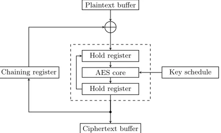
Hold register
AES core
Hold register
Key schedule Chaining register
Plaintext buffer
Ciphertext buffer
Fig. 7: Probable high-level architecture for the AES core within the AM335x cryptographic co-processor (CBC mode): note that various registers may be merged (e.g., input and output hold registers), and the chaining register should be initialised with an IV.
4.1 Experimental outline
As noted in Section 2.1, there is scant documentation for the AM335x crypto-graphic co-processor: our only insight into the internal design stems from device drivers that support interaction with it. Since the drivers do not expose any system calls for use by user processes, such interaction is realised concretely by enabling the OpenSSL cryptodev extension: each encryption operation in-voked is processed, by OpenSSL, via the associated cryptodev kernel module and ultimately performed by the co-processor.
Black-box architectural analysis. Treating the co-processor as a black-box, we
use the functionality offered (i.e., ECB, CBC and CTR modes, with 128-, 192-and 256-bit key sizes) 192-and the extensive literature on similar hardware designs to infer the (probable) internal design. Specifically, the registers exposed (e.g., for the IV) and requirement to reinitialise the key register per invocation (so the key schedule is likely recomputed for each encryption) suggest an iterative design: as illustrated by Figure 7, a single (combinatorial) core is likely used by surrounding control logic in multiple steps to realise each mode. The default driver behaviour capitalises on hardware DMA support, via the scatter-gather mechanism, to operate autonomously from the ARM core.
Signal hunting. During any exploration phase, it is important to first establish a)
unclear how AES is computed, we could not identify any periodic leakage signa-ture linked to the AES operation. This is complicated further by virtue of the fact that the co-processor operates (semi-)independently of the ARM core (thus any hardware trigger used will be asynchronous to encryption operations).
Without any visual cues nor a reliable trigger, we were unsuccessful in detect-ing leakage under fixed-versus-random tests at the probe locations identified in Section 3. Further attempts to manually scan the AM335x surface at alternative probe locations did not yield better results. However, we didmanage to detect the DMA strobes by locating a probe over the memory access region: these are, of course, inherently related to encryption operations and hence (to some degree) yield a (somewhat) synchronous trigger for activity by the co-processor. The difficulty with capitalising on this fact is thatanymemory intensive instruction sequence can cause false positives, rendering the trigger less reliable.
To combat this issue, we instead rely on saturating the DMA engine with
other work: this forces the driver into a non-DMA fall-back mode, which issues
interrupts for any memory management. These interrupts are used as a trigger for AES operations on the co-processor. While less ideal than the free-running scenario in Section 3, we argue thisisincrementally better than a GPIO-based hardware trigger. Specifically, it requires an attacker controlled process be co-resident on the target device (cf. “spy process” in access-driven cache attacks such as [36]) rather than invasive alteration of the target process.
Testing strategy. With the trigger mechanism active, we placed several probes
at various locations on the AM335x surface and repeated the same fixed-versus-random tests as above (using all available channels on the oscilloscope, sampling at a rate of 2.5 GS/s). Their repeated failure led us to abandon generic fixed-versus-random tests, and instead focus on more specifically tailored leakage de-tection test vectors. A test plan was developed to target several leakage models, using semi-fixed-versus-random [6, Section 5] test vectors. The only strategy to yield detectable leakage (which we focus on subsequently as a result) was Hamming distance; the associated test vectors force a small Hamming distance between round input and output. Figure 8 shows an averaged trace and the re-sulting t-test result (over 10,000 traces); note that the t-statistic far exceeds our significance threshold ofτ= 4.5.
Signal processing and detrending. Although the leakage detection step was
0 200 400 600 800 1000 1200
Sample Index
Sample
Amplitude
(a) Averaged trace.
0 200 400 600 800 1000 1200
Sample Index
−150 −100 −50 0 50 100 150 200 250 300
t-statistic
(b) Averaged t-test.
0 100 200 300 400
Sample Index
Sample
Amplitude
(Scaled
×
5
)
(c) Filtered trace.
0 100 200 300 400
Sample Index
−150
−100
−50
0 50 100 150 200 250 300
t-statistic
(d) Filtered t-test.
Fig. 8: Leakage detection test results for the AES co-processor running with a saturated DMA. The two columns relate to an averaged trace (left) and the related t-test result (right). The rows are indicative of raw unprocessed traces (top) and traces post-processed via the wavelet analysis (bottom).
level before resynthesising the (clean) signal. However, a high-magnitude, semi-correlated interference signal overlaid the low-magnitude signal of interest. Both signals separately had low-noise but the interference reduced the SNR of the signal of interest. As the interference contained overlapping frequencies with the signal of interest, a wavelet based detrending scheme, as used in [39], provided an effective and efficient approach for separation. After trying various wavelets, ones with a lower number of vanishing moments provided better results, indi-cating the need for a fast response to sudden changes in the interference [15,41]. The detrending technique follows a simple algorithm, inspired by the wavelet shrinkage techniques as described in [10,16]. First, perform the DWT [30] with the Haar wavelet. The low ratio of the sampling rate over frequency content of the signal required only a single level computed. Then, set all of the resulting approximation coefficients to zero before performing an inverse DWT on the detail coefficients. The resulting signal (shown in Figure 8) with the interference extracted, yields a stronger result from the leakage detection test.
4.2 Analysis and discussion
(a) AM335x surface.
0 2 4 6 8 10 12 14 16
relative x-position (mm)
0 2 4 6 8 10 12 14 16
relative
y-position
(mm)
3.0
4.5
6.0
7.5
9.0
10.5
12.0
13.5
t-statistic
(b) AM335x surface overlaid with heat-map.
Fig. 9: An illustration of results from the automatic AM335x surface scan, using a semi-fixed-versus-random strategy to identify leakage from the cryptographic co-processor running AES-256-CBC: the t-statistic highlights the region of in-terest (modulo fidelity of the probe versus the dimensions in question) used as a subsequent probe location.
1. Saturate the DMA mechanism such that the driver operates in the non-DMA fall-back mode.
2. Acquire n = 500,000 traces, each associated with 1 encryption operation and averaged overl = 1,000 trials; match these traces with the associated ciphertexts.
3. Apply wavelet post-processing to each trace to maximise SNR.
Note that our interrupt-based trigger offers the best alignment achievable; post-processing to improve alignment was impossible, due to the lack of an identifiable form for AES operations. The acquisition process took around 3 days. To exploit the leakage, we then applied a single-bit correlation-based attack: ifsi denotes
in the signal that suggests time-based hiding, but equally attempted higher-order attacks on possible masking strategies were unsuccessful. Either way, if
a countermeasure is implemented, then we conclude it only seems effective in increasing attack cost rather than preventing an attack.
5
NEON
NEON is a general-purpose SIMD extension to Cortex A-series ARM cores, harnessed, for example, by Bernstein and Schwabe [8] to both accelerate cryp-tographic workloads and deliver constant execution time. In terms of the ISA, each vector instruction w processes vector operands with l = nw elements (or sub-words), eachw-bits in size; n∈ {64,128} is determined by the instruction type (more specifically, whether the operands are double- or quad-words). For the simplest case of a pure vector operation, we can therefore say
r=xwy7→ hrw[0] =xw[0]
wyw[0], . . . , rw[l
−1] =xw[l
−1]wyw[l
−1]i
where tw[j] = t[j
·w, . . . ,(j+ 1)·w−1] is the j-th w-bit (scalar) sub-word
of vector t, and w is the operation for such sub-words. The ISA naturally captures standard logical (e.g., =⊕with w = 1) and arithmetic (e.g.,= + with w = 8, w = 16 or w = 32) operations, plus various more specialist extensions. Note that although the semantics of quad-word NEON instructions suggest they process 128-bit operands, the pipeline will in fact issue two 64-bit micro-operations.
5.1 Instruction-level characterisation
In this section we study leakage from (a subset of) NEON instructions by focus-ing on observation of
ri=DUT
w
(xi,yi) λi
for a range of w but, without loss of generality, on w∈ {8,32} bit sub-words within double-word, i.e.,n= 64 bit, operands. Given that the NEON pipeline is tightly coupled to the ARM pipeline, we reason the two will be physically close on the AM335x surface; as such, we retain the same experimental configuration (e.g., same probe location) as Section 3. However, our specific remit means we compromise by using a strictly controlled profiling device: a hardware trigger is used throughout to support instruction-level (i.e., cycle-accurate) alignment and hence a lower bound on success rate.
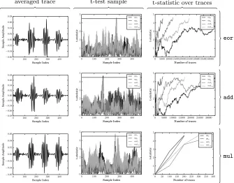
Leakage detection. We performed an initial exploration focused on a limited,
0 50 100 150 200 250
Sample Index −0.6
−0.4
−0.2 0.0 0.2 0.4 0.6
Sample
Amplitude
0 50 100 150 200 250
Sample Index 0 1 2 3 4 5 t-statistic
0 5000 10000 15000 20000 25000
Number of traces
0 1 2 3 4 5 t-statistic
0 50 100 150 200 250
Sample Index −0.6
−0.4
−0.2 0.0 0.2 0.4 0.6
Sample
Amplitude
0 50 100 150 200 250
Sample Index 0 1 2 3 4 5 t-statistic
0 5000 10000 15000 20000 25000
Number of traces
0 1 2 3 4 5 t-statistic
0 50 100 150 200 250
Sample Index −0.4
−0.2 0.0 0.2 0.4
Sample
Amplitude
0 50 100 150 200 250
Sample Index 0 1 2 3 4 5 t-statistic
0 5000 10000 15000 20000 25000
Number of traces
0 1 2 3 4 5 t-statistic
0 50 100 150 200 250
Sample Index −0.4
−0.3
−0.2
−0.1 0.0 0.1 0.2 0.3
Sample
Amplitude
0 50 100 150 200 250
Sample Index 0 1 2 3 4 5 t-statistic
0 20000 40000 60000 80000 100000
Number of traces
0 1 2 3 4 5 t-statistic
averaged trace t-test sample t-statistic over traces
veor.32
vadd.32
vmul.32
vceq.32
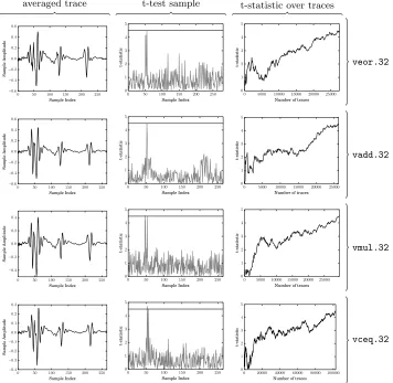
In summary, the results (as illustrated in Figure 10) show that a) clear operation-dependent SPA leakage is evident, allowing, for example, construc-tion of per-instrucconstruc-tion templates, and b) data-dependent leakage is evident, but from result write-back only: we could identify no leakage relating to operand reads. The latter fact, i.e., the statistically observable difference between write-back of random versus fixed results, confirms that the leakage point relates to said step (not reading operands from memory).
Comparing the ARM and NEON cores. Section 3 already shows that exploitable
leakage from the ARM core exists; our next goal was to roughly quantify the difference between it and the NEON core. In summary, applying the same leak-age detection strategy (as illustrated in Figure 11) shows that on the ARM core a) leakage from the operation plusboth operand reads and result write-back is evident, and b) the strength of that leakage (in terms of the t-statistic growth per sample count) is greater than on the NEON core (especially for the integer multiplication instruction). Explaining this difference seems difficult without de-tailed knowledge of the implementation(s). However, itsuggests a difference in the arithmetic (e.g., multiplier) design used.
Hamming weight leakage. Having identified a set of leakage points, our next
goal was to analyse and exploit their structure. More specifically, we attempted to align the characterisation with standard attacks by tracking the Hamming weight of results written-back against associated leakage. This is achieved by amending the fixed-versus-random methodology, so semi-fixed test vectors are selected (for a given Hamming weight).
The results of this analysis, plus their utility, are discussed in the following sections. We stress that, throughout, the Hamming weight of the entire n-bit result is considered: our results show that focusing on an individual w-bit sub-wordisfeasible, but with the expected increase the number of traces. That is, if one considers leakage with regards to a singlew-bit sub-word then the otherl−1 sub-words can be considered noise (thus overcome by acquiring more traces).
Arithmetic and logical operations. Figure 12 illustrates leakage from two
spe-cific NEON instructions pertinent to cryptography; further examples are shown in Figure 13. The (vector) XOR case is indicative of most instructions, in the sense that clear separation between distinct Hamming weights is evident. In con-trast, the vector polynomial multiplication is something of a special case. The separation between distinct Hamming weights is still evident, and potentially relevant to cryptographic use-cases (e.g., [9]). However, unlike the other instruc-tions there is some “cross over” with regard to the Hamming weight and signal that we cannot currently explain.
Comparison operations. Figure 14 illustrates leakage from a NEON vector
0 100 200 300 400
Sample Index −0.06
−0.04
−0.02 0.00 0.02 0.04 0.06 0.08
Sample
Amplitude
0 100 200 300 400
Sample Index 0 1 2 3 4 5 t-statistic opx opy outr outrD
0 5000 10000150002000025000300003500040000
Number of traces
0 1 2 3 4 5 t-statistic opx opy outr outrD
0 100 200 300 400
Sample Index −0.08
−0.06
−0.04
−0.02 0.00 0.02 0.04 0.06 0.08
Sample
Amplitude
0 100 200 300 400
Sample Index 0 1 2 3 4 5 t-statistic opx opy outr outrD
0 500010000 15000 20000 25000 30000
Number of traces
0 1 2 3 4 5 t-statistic opx opy outr outrD
0 100 200 300 400
Sample Index −0.06
−0.04
−0.02 0.00 0.02 0.04 0.06
Sample
Amplitude
0 100 200 300 400
Sample Index 0 1 2 3 4 5 t-statistic opx opy outr outrD
0 50 100 150 200 250 300 350 400
Number of traces
0 1 2 3 4 5 t-statistic opx opy outr outrD
averaged trace t-test sample t-statistic over traces
eor
add
mul
0 20 40 60 80 100 120
Sample Index
−0.10
−0.05
0.00 0.05 0.10
Sample Amplitude 0 8 16 24 32 40 48 56 64 Hamming W eight
(a)veor.u32instruction (raw).
59.5 60.0 60.5 61.0 61.5 62.0
Sample Index
0.075 0.080 0.085 0.090 0.095 0.100
Sample Amplitude 0 8 16 24 32 40 48 56 64 Hamming W eight
(b)veor.u32instruction (zoom).
0 20 40 60 80 100 120
Sample Index
−0.08
−0.06
−0.04
−0.02
0.00 0.02 0.04 0.06 0.08
Sample Amplitude 0 8 16 24 32 40 48 56 64 Hamming W eight
(c)vmul.p8instruction (raw).
65.5 66.0 66.5 67.0 67.5
Sample Index
0.0680 0.0685 0.0690 0.0695 0.0700 0.0705 0.0710
Sample Amplitude 0 8 16 24 32 40 48 56 64 Hamming W eight
(d)vmul.p8instruction (zoom).
Fig. 12: Illustration of Hamming weight leakage for a (limited) set of NEON arithmetic and logical instructions (where w= 32).
mask). Without loss of generality, we focus on equality comparison:
rw[j] =
2w−1 ifxw[j] =yw[j],
0 otherwise.
This can be used to support branch-free, constant-time implementations: the resulting mask is used to control conditional execution of subsequent operations in each sub-word, replacing conditionalcontrol-flow by conditionaldata-flow.
Our results demonstrate two important facts. First, analysis of leakage from a vector comparison reveals the (total) number of sub-word results that were true (or false); this is as expected, given the maximal and minimal Hamming weight of the outputs (i.e., masks) produced in each case. Second, as demonstrated by Figure 16, it is possible to target a specific sub-word, and hence ascertain whether it has the value 2w−1 or 0. Doing so means considering each sub-word independently, treating the remaining sub-words as noise (cf. single-bit DPA).
5.2 A concrete attack on AES
The charactisation above clearly suggests Hamming weight leakage can be lever-aged in concrete attacks. As justification, we consider a scenario where the at-tacker can observe computation of
0 20 40 60 80 100 120
Sample Index −0.10
−0.05 0.00 0.05 0.10
Sample Amplitude 0 8 16 24 32 40 48 56 64 Hamming W eight
57.5 58.0 58.5 59.0 59.5
Sample Index
0.045 0.046 0.047 0.048 0.049 0.050
Sample Amplitude 0 8 16 24 32 40 48 56 64 Hamming W eight
0 20 40 60 80 100 120
Sample Index −0.08
−0.06
−0.04
−0.02 0.00 0.02 0.04 0.06 0.08
Sample Amplitude 0 8 16 24 32 40 48 56 64 Hamming W eight
59.5 60.0 60.5 61.0 61.5
Sample Index
0.066 0.068 0.070 0.072 0.074 0.076 0.078 0.080
Sample Amplitude 0 8 16 24 32 40 48 56 64 Hamming W eight
0 20 40 60 80 100 120
Sample Index −0.08
−0.06
−0.04
−0.02 0.00 0.02 0.04 0.06 0.08
Sample Amplitude 0 8 16 24 32 40 48 56 64 Hamming W eight
63.5 64.0 64.5 65.0 65.5 66.0
Sample Index
0.006 0.008 0.010 0.012 0.014 0.016 0.018 0.020
Sample Amplitude 0 8 16 24 32 40 48 56 64 Hamming W eight
raw trace zoomed trace
vadd.u32
vsub.u32
vmul.u32
0 20 40 60 80 100 120
Sample Index
−0.08
−0.06
−0.04
−0.02
0.00 0.02 0.04 0.06 0.08
Sample
Amplitude
0 matches 1 matches 2 matches
(a)vceq.u32instruction (raw).
48.0 48.5 49.0 49.5 50.0
Sample Index
−0.034
−0.032
−0.030
−0.028
−0.026
Sample
Amplitude
0 matches 1 matches 2 matches
(b)vceq.u32instruction (zoom).
Fig. 14: Illustration of Hamming weight leakage for NEON comparison instruc-tions (wherew= 32).
0 200 400 600 800 1000 1200
Sample Index
0.00 0.05 0.10 0.15 0.20 0.25
Amplitude
(a) Single averaged trace.
0 5000 10000 15000 20000 25000 30000
Number of Traces
−0.20
−0.15
−0.10
−0.05 0.00 0.05 0.10 0.15 0.20
Correlation
(b) Single byte correlation.
Fig. 15: Illustration of decryption (for a 128-byte ciphertext) using the NEON-based bit-sliced implementation of AES in OpenSSL; the corresponding correla-tion coefficient evolucorrela-tion suggests the attack succeeds with∼5,000 traces.
but alter how AES itself is realised (compared with Section 3 and Section 4): we instead target the NEON-based bit-sliced implementation in OpenSSL (which stems from work by K¨asper and Schwabe [27], and was enabled via the pre-processor flag-DBSAES_ASM).
This particular implementation is triggered ifci is sufficiently large (namely
128 bytes, falling-back to an alternative implementation otherwise). Although we note the techniques in Section 3 remain broadly applicable, for clarity we retain the same experimental environment as Section 5.1 (e.g., with a hardware trigger). The attack then proceeds in a fairly straightforward manner: we simply use key (byte, due to the representation of data used by the implementation) hypotheses based on Hamming weight of the intermediate state after the first round InvSubBytes operation in a standard, correlation-based approach. The attack succeeds with∼5,000 traces, requiring 5000·128 = 625 kB of ciphertext.
5.3 A theoretical attack on NORX
0 20 40 60 80 100 120
Sample Index
−3
−2
−1
0 1 2 3
Difference
of
Means
×10−4
(a) Sample difference.
0 500 1000 1500 2000
Number of Averaged Trials
−6
−4
−2
0 2 4 6
Difference
of
Means
×10−4
(b) Difference over averaged trials.
Fig. 16: Illustration of a single-word attack on vceq.u32: the black hypothesis forrw[j] = 2w
−1 (i.e., where the comparison is true, without loss of generality forj= 0) is clearly distinguished after averaging over 1,000 trials.
CAESAR candidate whose reference implementation8 harnesses NEON. The NORX32-6-1 parametrisation (i.e., for 32-bit word size, 6 rounds, parallelism degree 1, and 128-bit tag size) verifies tags as follows
/* V e r i f y t a g */
A = v c e q q _ u 3 2 ( A , L O A D U ( c + 0 ) ) ;
r e t u r n 0 x F F F F F F F F == ( v g e t q _ l a n e _ u 3 2 ( A , 0) & v g e t q _ l a n e _ u 3 2 ( A , 1) &
v g e t q _ l a n e _ u 3 2 ( A , 2) & v g e t q _ l a n e _ u 3 2 ( A , 3)) ? 0 : -1;
noting the stateA(representing the computed tag) is compared with the received tag using vector comparison on 32-bit sub-words.
On one hand this is attractive since a) it is likely more efficient than four sequential 32-bit comparisons, and b) it is constant-time, unlike an alternative such as use of memcmp. On the other hand, consider a (purely hypothetical) scenario where an attacker has access to a decryption oracle, i.e., execution of
DUTNORX32-6-1k (ci) λi
for chosen ci can be observed. The resulting leakage can be used to enable tag
forgery: the attacker is able to determine the total number of matching sub-words for a candidate tag, so requiresO(232) queries (albeit with a constant factor that hides the cost of dealing with noise etc. in acquisitions) to brute-force search for a tag matching ciphertext of their choice. Whether or not such an approach is feasible in practice clearly depends on the context, but equally clear is the gap between this and the supposed (theoretical) security level.
6
Conclusions
Summary of results. In this paper we present concrete, EM-based analysis of the
AM335x SoC and software executing on it. Although hard to compare directly, a
8
Section Operation Implementation Hardware Trigger Acquisitions Data
3 Decryption T-tables ARM core GPIO-based 3,000 46 kB
3 Encryption T-tables ARM core Network-based 100 400 kB
4 Encryption Hardware Co-processor DMA-based 500,000 7 GB
5 Decryption Bit-sliced NEON core GPIO-based 5,000 625 kB
Table 1: Summary of results.
summary of our results targetting CBC-based AES is shown in Table 1. Beyond this, however, we draw several more general conclusions:
1. Despite suggestions to the contrary [32], higher clock frequency does not
implya requirement for a high sampling rate: instruction- or cycle-level
res-olutionmayyield better results, but we still observed exploitable leakage at much lower frequencies (mirroring observations such as in [22]). This fact refutes any suggestion that the impact of EM-based attacks (against targets of this complexity) is lessened by cost: for example, in Section 3 a (post-characterisation, i.e., excluding the XY-table) attack can be mounted using
∼$1,800 of equipment (including a suitable low-end oscilloscope in place of the digitiser, and hand-made 30 AWG coil, 15-turn probe).
2. For devices of this complexity, the value offered by the TVLA methodology is significant: we suggest that an ad hoc analysis would have been difficult or ineffectual, particularly in the context of an unknown target (as in Section 4). 3. Target complexity suggested at a high level does notimply the same com-plexity at lower levels. Our results demonstrate this fact in two examples. First, we were able to bypass complexity relating to the SoC architecture or fabrication technology by targeting support circuitry in Section 3. Second, in Section 5, we observed that parallelism suggested in the NEON ISA (tradi-tionally viewed as a complicating factor in DPA, for example) is not realised in the micro-architecture: This is of relevance to constructions (e.g., [33], albeit studied in the context of hardware) thatrelyon parallelism somehow. 4. Although the drive for efficient, constant-time implementation using NEON is clearly important, it seems prudent to proactively consider when/how such an approach can enable other forms of leakage. For example, Section 5 demonstrates that vector comparison, while advantageous in the sense of having a fixed latency, will still leak information about sub-word (in)equality. 5. Software such as OpenSSL is now becoming commonplace in (embedded) scenarios in which it might traditionally have been deemed too heavy-weight. As a result, alongside the challenging goal of securing such software against network-based attacks, it is starting to seem of long-term importance that countermeasures for hardware side-channels are also proactively considered.
Future work. Our limited scope suggests various items of future work; beyond
obvious directions, such as analysis of asymmetric cryptography on the platform, two stand out. First, a rigorous analysis ofallconstituent components is of gen-eral value. For example, although we deemed the9SHA, RNG and support out of
9
scope, understanding their leakage characteristics seems important. In the same way, an exhaustive analysis of the NEON unit was impractical in this paper (due to space), even though the techniques easily extend to other instructions. Doing so, and, in particular, understanding vector instructions with no natural scalar equivalent, also seem important. Second, improvements in analysis techniques could incrementally improve specific results. For example, in Section 3 the num-ber of acquisitions required to perform a successful key recovery attack is partly dictated by how effective the pre-processing is: we expect some effort to narrow the gap between results for the artificial and free-running cases. Likewise, Sec-tion 4 highlights the challenge of translating a method of leakage detecSec-tion into a leakage model; resolving this issue in the black-box setting seems difficult, but clearly important in scenarios such as the one investigated.
Acknowledgements
Jake Longo has been supported in part by a studentship under the EPSRC Doctoral Training Partnership (DTP) scheme. The authors would like to thank Pankaj Rohatgi for general discussion, and Sami Saab for specific help with signal processing/analysis. We also thank both Billy Brumley and Markku Saarinen for their insight on NEON-based implementation, Martijn Stam for discussion about AEAD, and the NORX team, all of who help improved Section 5.
References
1. D. Aboulkassimi, M. Agoyan, L. Freund, J.J.A. Fournier, B. Robisson, and A. Tria.
ElectroMagnetic Analysis (EMA) of software AES on Java mobile phones. In
Information Forensics and Security (WIFS), pages 1–6, 2011.
2. D. Aboulkassimi, J.J.A. Fournier, L. Freund, B. Robisson, and A. Tria. EMA as a
physical method for extracting secret data from mobile phones.IJCSA, 2(1):16–25,
2013.
3. D. Agrawal, B. Archambeault, J.R. Rao, and P. Rohatgi. The EM side-channel(s).
InCHES, pages 29–45. LNCS 2523, 2003.
4. J.-P. Aumasson, P. Jovanovic, and S. Neves. NORX. CAESAR submission
speci-fication, version 1.1, 2014. http://norx.io/data/norx.pdf.
5. J. Balasch, B. Gierlichs, R. Verdult, L. Batina, and I. Verbauwhede. Power analysis
of Atmel CryptoMemory – recovering secret keys from secure EEPROMS. In
CT-RSA, pages 19–34. LNCS 7178, 2012.
6. G.T. Becker, J. Cooper, E. DeMulder, G. Goodwill, J. Jaffe, G. Kenworthy, T. Kouzminov, A. Leiserson, M. Marson, P. Rohatgi, and S. Saab. Test Vector
Leakage Assessment (TVLA) methodology in practice. InICMC, 2013.
7. G.T. Becker, M. Kasper, A. Moradi, and C. Paar. Side-channel based watermarks
for IP protection. InCOSADE, pages 47–50, 2010.
8. D.J. Bernstein and P. Schwabe. NEON crypto. InCHES, pages 320–339. LNCS
7428, 2012.
9. D. Cˆamara, C.P.L. Gouvˆea, J. L´opez, and R. Dahab. Fast software polynomial
multiplication on ARM processors using the NEON engine. InCD-ARES, pages
10. X. Charvet and H. Pelletier. Improving the DPA attack using wavelet transform.
InNIST Physical Security Testing Workshop, 2005.
11. T. Chothia and A. Guha. A statistical test for information leaks using continuous
mutual information. InCSF, pages 177–190, 2011.
12. O. Choudary and M.G. Kuhn. Efficient template attacks. In CARDIS, pages
253–270, 2013.
13. O. Choudary and M.G. Kuhn. Template attacks on different devices. InCOSADE,
pages 179–198, 2014.
14. J. Daemen and V. Rijmen. The Design of Rijndael. Springer, 2002.
15. I. Daubechies. Ten Lectures on Wavelets. CBMS-NSF Regional Conference Series
in Applied Mathematics. Society for Industrial and Applied Mathematics, 1992. 16. N. Debande, Y. Souissi, M.A.E. Aabid, S. Guilley, and J. Danger. Wavelet
trans-form based pre-processing for side channel analysis. In MICROW, pages 32–38,
2012.
17. D.L. Donoho. De-noising by soft-thresholding.IEEE Transactions on Information
Theory, 41(3):613–627, 1995.
18. D.L. Donoho and I.M. Johnstone. Ideal spatial adaptation by wavelet shrinkage.
Biometrika, 81(3):425–455, 1994.
19. D. Du, S. Narasimhan, R. Subhra Chakraborty, and S. Bhunia. Self-referencing:
A scalable side-channel approach for hardware Trojan detection. InCHES, pages
173–187. LNCS 6225, 2010.
20. T. Eisenbarth, T. Kasper, A. Moradi, C. Paar, M. Salmasizadeh, and M.T. Manzuri Shalmani. On the power of power analysis in the real world: A complete break of
the KeeLoq code hopping scheme. InCRYPTO, pages 203–220. LNCS 5157, 2008.
21. K. Gandolfi, C. Mourtel, and F. Olivier. Electromagnetic analysis: Concrete results.
InCHES, pages 251–261. LNCS 2162, 2001.
22. D. Genkin, L. Pachmanov, I. Pipman, and E. Tromer. Stealing keys from PCs by radio: Cheap electromagnetic attacks on windowed exponentiation. Cryptology
ePrint Archive, Report 2015/170, 2015. http://eprint.iacr.org/.
23. G. Goodwill, B. Jun, J. Jaffe, and P. Rohatgi. A testing methodology for
side-channel resistance validation. In NIST Non-Invasive Attack Testing Workshop,
2011.
24. B. Heinz, J. Heyszl, and F. Stumpf. Side-channel analysis of a high-throughput
AES peripheral with countermeasures. InISIC, pages 25–29, 2014.
25. Cryptography Research Inc. Test Vector Leakage
Assess-ment (TVLA) Derived Test Requirements (DTR) with AES.
http://www.cryptography.com/public/pdf/TVLA-DTR-with-AES.pdf.
26. Texas Instruments. AM335x Sitara processor datasheet. Technical Report
SPRS717G, TI, 2014. http://www.ti.com/lit/ds/symlink/am3358.pdf.
27. E. K¨asper and P. Schwabe. Faster and timing-attack resistant AES-GCM. In
CHES, pages 1–17. LNCS 5747, 2009.
28. M. Kasper, T. Kasper, A. Moradi, and C. Paar. Breaking KeeLoq in a flash: On
extracting keys at lightning speed. In AFRICACRYPT, pages 403–420. LNCS
5580, 2009.
29. P.C. Kocher, J. Jaffe, and B. Jun. Differential power analysis. InCRYPTO, pages
388–397. LNCS 1666, 1999.
30. S.G. Mallat. A theory for multiresolution signal decomposition : the wavelet
rep-resentation. IEEE Transactions on Pattern Analysis and Machine Intelligence,
11(7):674–693, 1989.
31. S. Mangard, E. Oswald, and T. Popp.Power analysis attacks: Revealing the secrets
32. E. Mateos and C.H. Gebotys. Side channel analysis using Giant Magneto-Resistive
(GMR) sensors. InCOSADE, pages 42–49, 2011.
33. M. Medwed, F.-X. Standaert, and A. Joux. Towards super-exponential side-channel
security with efficient leakage-resilient PRFs. InCHES, pages 193–212. LNCS 7428,
2012.
34. A. Moradi, A. Barenghi, T. Kasper, and C. Paar. On the vulnerability of FPGA bitstream encryption against power analysis attacks: extracting keys from Xilinx
Virtex-II FPGAs. InCCS, pages 111–124, 2011.
35. A. Pellegrini, V. Bertacco, and T. Austin. Fault-based attack of RSA
authentica-tion. InDATE, pages 855–860, 2010.
36. C. Percival. Cache missing for fun and profit, 2005. http://www.daemonology.
net/papers/htt.pdf.
37. J.-J. Quisquater and D. Samyde. ElectroMagnetic Analysis (EMA): Measures and
counter-measures for smart cards. InE-SMART, pages 200–210. LNCS 2140, 2001.
38. P. Rohatgi. Electromagnetic attacks and countermeasures. InCryptographic
En-gineering, pages 407–430. Springer, 2009.
39. S. Saab, A. Leiserson, and M. Tunstall. Efficient key extraction from the pri-mary side of a switched-mode power supply. Cryptology ePrint Archive, Report
2015/512, 2015. http://eprint.iacr.org/.
40. J. Scahill and J. Begley. iSpy: The CIA campaign to steal Apple’s
se-crets. The Intercept, 2015. http://firstlook.org/theintercept/2015/03/10/
ispy-cia-campaign-steal-apples-secrets/.
41. G. Strang and G.J. Fix. An Analysis of the Finite Element Method. Automatic
Computation. Prentice-Hall, 1973.
42. H. Uno, S. Endo, Y. Hayashi, N. Homma, and T. Aoki. Chosen-message
elec-tromagnetic analysis against cryptographic software on embedded OS. InEMC,
2014.
43. A. Zajic and M. Prvulovic. Experimental demonstration of electromagnetic
infor-mation leakage from modern processor-memory systems. IEEE Transactions on
Electromagnetic Compatibility, 56(4):885–893, 2014.
A
TVLA plan and test vector generation
Throughout the paper, we make use of the Test Vector Leakage Assessment (TVLA) methodology [25,6,23] for leakage detection and analysis. This Appendix aims to clarify how the associated test vectors were generated, hence adding detail to discussion within the paper itself.
A.1 TVLA as per Section 3
Test Description Result Trace count
Round 7, round Hamming distance, 11 bytes @0x00 Leak 3,000
Round 7, round Hamming distance, 6 bytes @0x00 Leak 25,000
Round 7, round Hamming distance, 3 bytes @0x00 No Leak 10,000
Round 7, round Hamming distance, byte 1 @0x00 No Leak 10,000
Round 7, fixed round output, byte 1 @0x00 No Leak 10,000
Round 7, S-box out, byte 1 @0x00 No Leak 10,000
Round 7, round Hamming distance, byte 1 @0xFF No Leak 10,000
Round 7, round Hamming distance (beforeAddRoundKey, byte 1 @0x00No Leak 10,000
Round 7, round Hamming distance, byte 12 @0x00 No Leak 10,000
Round 7, round Hamming distance, byte 4 @0x00 No Leak 10,000
Round 7, fixed output, byte 12 (beforeAddRoundKey) @0x00 No Leak 10,000
Round 14, S-box out, byte 1 @0x00 No Leak 10,000
Round 7, fixed state byte @0x00 No Leak 10,000
Round 7, fixed state short @0x00 No Leak 10,000
Round 7, fixed state word @0x00 No Leak 10,000
Round 7, fixed state 64-bit @0x00 No Leak 10,000
Three round Hamming distance @ 7-9, multiple bytes @0x00 Leak 200
Three round Hamming distance @ 6-8, multiple bytes @0x00 Leak 200
Round 7, S-box in/out Hamming distance minimised No Leak 1,000
Round 7, S-box in/out Hamming distance maximised No Leak 1,000
Round 7, S-box output 16 bytes @0x00 No Leak 1,000
Table 2: TVLA test plan, and results, as discussed in Section 4. Note that traces are averaged over 1,000 trials (i.e., 1,000 traces equates to 1 million trials).
A.2 TVLA as per Section 4
In sharp contrast with OpenSSL, the AM335x cryptographic co-processor is a proprietary design: with no explicit documentation, we were forced to apply (informed) black-box analysis and hence develop a test plan to identify potential leakage points. Table 2 lists (a subset of) the test vectors used, which were developed according to the recommendations by Becker et al.[6] and the AES-specific TVLA requirements [25]; leakage is deemed to be evident if the t-statistic associated with a given test vector exceedsτ = 4.5.
A set of test vectors are designed to trigger specific behaviour in AES that may lead to leakage detection. For example, the test “Round 7, round Hamming distance, 11 bytes @ 0x00” will fix (the same) 11 bytes in D(s(6), s(7)) to zero whilst the remaining 5 bytes vary. Note, that for some vectors this may result in some intermediate round functions also being fixed. Each of the vectors are run on the hardware co-processor operating in AES-256-CBC mode.
A.3 TVLA as per Section 5
Ensuring isolation of NEON core versus ARM core and memory access. We
x32[0] x32[1]
y32[0] y32[1]
32 32
r32[0] r32[1]
Fig. 17: An illustration of the NEON instructionr=x32y.
memory access by the NEON core. Likewise, our analysis showed that instruc-tions executed by the ARM core exhibited strong leakage. A subtle implied issue is that we need to ensure that the leakage observed was solely from the in-structions being studied (as executed by the NEON core, versus leakage related memory access for example). To do so, we placed an adequate NOP sled on ei-ther side of the instruction being studied. We concede that this limits the scope of our analysis to exclude cross-instruction behaviour, but feel that this is an acceptable trade-off based on our original remit.
NEON fixed-versus-random test vector generation. We target four modes of
leak-age for the NEON processor, namely, the input operands (opx,opy), the output
(outr) and the output write-back stage (outrD). Furthermore, care needs to be
taken to primarily capture the leakage for a single lane of each instruction. We ran extensive analysis for all data widths (8,16,32,64) where possible, however, we primarily discuss results related to the 32-bit data-width case (see Figure 17 and Table 3). The leakage detection results showed no discernible leakage for either input operands and relatively little difference between outr and outrD.
This suggests the leakage is primarily a function of the output bits inr. This is perhaps unsurprising as we often find that the leakage is closely related to the Hamming weight of a particular state.
Hamming weight analysis of NEON instructions. We focused on the Hamming
Registers
Notes
x y r
opx fixed random random
opy random fixed random
outr pseudorandom pseudorandom fixed r=x32y.
rrandomised
prior to execution.
outrD pseudorandom pseudorandom fixed r=x32y.
rfixed prior to
execution.
Table 3: TVLA test models for NEON operations, as discussed in Section 5.
h g
↓
↓ A[1]
D[1]
h g
↓
↓ A[2]
D[2]
h g
↓
↓ A[n]
D[n]
Fig. 18: Ann-level DWT filter bank.
B
Wavelet analysis
Wavelet analysis is a powerful method of analysing the time-frequency content of a signal with respect to a wavelet function (the mother wavelet ψ). Specifi-cally, the signal is described as a function (shifting and dilation) of the mother wavelet. This offers advantages over a short-time Fourier transform, which has a limited frequency resolution based on the window size used. Generally, wavelet transforms are divided into two approaches, namely the Continuous Wavelet Transform (CWT) and the Discrete Wavelet Transform (DWT).
Continuous Wavelet Transform. The CWT is the convolution of a signal f(t)
with a set of transformations (shifting and dilation) of the mother wavelet. More formally, the CWT for a sampled signalf(t) is defined as:
CW T(d, s) = √1
d Z
f(t)ψ
t−s
d
dt
Discrete Wavelet Transform. The DWT is similar to the Fourier transform in how it decomposes a signal into a set of terms of a basis set of functions. However, the key difference is that the Fourier transform basis functions consist of sines and cosines, whereas the DWT basis functions are a set of mutually orthogonal wavelets generated from the mother wavelet. In addition, the DWT will use two parameters in the expansion, i.e. the dilation and shift factors. In effect, the DWT acts as a filter bank and the depth of the bank describes the level of the transform.
At each level of the filter bank, the frequency content of a discrete time signal is split by way of a low and high pass filter g and h respectively. The output from each of the filters now contains half the frequency information previously present. Following Nyquist, we can down-sample the data and remove half the points in the signal. The resulting signals are termed the details (denoted D)
and approximations (denoted A) for the high and low frequency components
respectively. Each subsequentilevel of DWT applies the same process toA[i−1],
![Fig. 1: A block diagram of the AM335x SoC, replicating [26, Figure 1-1]; note thatcomponents and sub-systems pertinent to sections in the paper are highlighted.](https://thumb-us.123doks.com/thumbv2/123dok_us/7932955.1317195/3.612.201.411.104.289/diagram-replicating-figure-thatcomponents-systems-pertinent-sections-highlighted.webp)