R E S E A R C H
Open Access
A unified message-passing algorithm for
MIMO-SDMA in software-defined radio
Alexander Kocian
1*, Mihai-Alin Badiu
2, Bernard Henri Fleury
2, Francesca Martelli
3and Paolo Santi
3,4Abstract
This paper presents a novel software radio implementation for joint channel estimation, data decoding, and noise variance estimation in multiple-input multiple-output (MIMO) space division multiple access (SDMA). In contrast to many other iterative solutions, the proposed receiver is derived within the theoretical framework of a unified message-passing algorithm, combining belief propagation (BP) and the mean field approximation (MF) on the corresponding factor graph. The algorithm minimizes the region-based variational free energy in the system under appropriate conditions and, hence, converges to a fixpoint. As a use-case, we consider the high-rate packet-oriented IEEE 802.11n standard. Our receiver is implemented on a software-defined radio platform dubbed MIMONet, composed of a GNU radio software component and a universal software radio peripheral (USRP). The receiver was evaluated in real indoor environments. The results of our study clearly show that, once synchronization issues are properly addressed, the BP-MF receiver provides a substantial performance improvement compared to a
conventional receiver also in real-world settings. Such improvement comes at the expense of an increase in running time that can be as high as 87. Therefore, the trade-off between communication performance and receiver
complexity should be carefully evaluated in practical settings.
Keywords: MIMO communications, Space division multiple access, Belief propagation, Mean field approximation, Factor graphs, Software-defined radios
1 Introduction
Multiple-input multiple-output (MIMO) technology is popular in wireless communications due to the increased spectrum efficiency brought along by the use of multiple antennas in transmission, reception, or both. A further performance improvement is possible when MIMO tech-nology is used in combination with orthogonal frequency division multiplexing (OFDM) modulation, namely, when different streams of information bits are modulated on orthogonal subcarriers.
The basic role of the receiver is to decode the infor-mation bits from the received signal which is affected by various unknown factors, such as the channel response and receiver noise. Receivers were originally designed to process the received signal in a cascaded fashion, starting with synchronization, then channel estimation, equaliza-tion, and finally decoding. Building on the intuition that
*Correspondence: [email protected]
1Department of Computer Science, University of Pisa, Largo B. Pontecorvo 3, 56127 Pisa, Italy
Full list of author information is available at the end of the article
(soft) information generated by one module can actually be re-used as a refined input to other modules, a multitude of receiver structures performing iterative, “turbo”-like processing have been proposed in the literature. Results unequivocally show substantial performance gains com-pared to non-iterative architectures. However, separate design of the individual modules cannot provide the guar-antee of global optimality or convergence. Moreover, it is not clear what type of information the modules should exchange and how to combine/process it. In recent years, several works have looked at the receiver design from the perspective of Bayesian inference on graphical models [1]. The use of formal frameworks for approximate infer-ence allows for a principled design of iterative receiver structures. Among the various algorithms for approximate inference [1], the belief propagation (BP) algorithm [2] (also referred to as sum-product algorithm [3]) is the most celebrated one. The algorithm operates by passing messages on the so-called factor graph, which represents the factorization of the probabilistic model of the com-munication system. The algorithm is able to compute
exact marginal probability density functions (pdfs) only when the factor graph is cycle free; otherwise, it outputs approximations of the marginal pdfs. Still, it was shown to work well in many graphs with cycles. This led to its widespread use in digital communications [3, 4]. However, BP usually yields intractable computations in probabilistic models with mixed discrete and continuous variables (see, e.g., [5]), which is also the case with our MIMO model. Different from BP, the mean field (MF) approximation [1] is a variational inference method that has been suc-cessfully applied to continuous probabilistic models. The algorithm also admits a message-passing formulation [6], and typically has simple closed-form message com-putation, especially for conjugate-exponential models. Its main drawback is that, for some models, the provided solution is not accurate enough, due to the underly-ing approximation of the joint posterior pdf (see [1] for more details). When the probabilistic model contains both continuous and discrete variables and the dependencies between them are both deterministic and stochastic, it is advantageous to apply the BP and MF algorithms in those parts of the factor graph where they are most suitable. For this purpose, we employ the recently proposed unifying inference framework that combines BP and MF [7]. In a nutshell, the factor graph is divided into two parts, the BP part and the MF part, where, respectively, BP-like and MF-like messages are computed. The framework states clear message computation rules, including specific expressions for the messages to be passed between the two parts. The unified nature of the algorithm resides in the fact that it iteratively optimizes a single objective function. Having derived a BP-MF-based MIMO-space division multiple access (SDMA) receiver in [8], we want to adapt and test it in real channels using software-defined radio (SDR).
SDR systems are becoming commonly used in the wireless networking research community due to their flexibility in rearranging different communication archi-tectures with limited effort. Three key virtues of SDR are reconfigurability, intelligence, and flexibility [9]. To reduce hardware integration costs and to increase flexibility in implementing the physical layer at the same time, SDR systems run functional modules— such as synchronization, modulation/de-modulation, coding/decoding, interleaving/de-interleaving, and chan-nel parameter estimation—in a software that is executed on personal computers. Therefore, SDR technology facil-itates implementation of reconfigurable radio systems where dynamic selection of parameters for the aforemen-tioned modules is possible. The literature reports a num-ber of SDR test-beds, designed to test network-level pro-tocols. Popular among them are theWireless Open Access Research Platform (WARP) [10, 11] developed at Rice University and the Microsoft Research Software Radio (MS-SORA) [12]. Hydra [13], developed at the University
of Texas at Austin, is a SDR testbed comprising radio soft-ware by GNU (recursive acronym for “GNU’s Not Unix”) and universal software radio peripheral (USRP)by Ettus Research™ [14]. The media access control layer (MAC) and the physical layer (PHY) design of Hydra implements the IEEE 802.11 distributed coordination function and a
2×2 MIMO-OFDM based on the IEEE 802.11a/g
stan-dard, respectively. Since then USRP hardware/GNU radio software was used to implement and test a series of heuris-tic receivers at PHY [15–17], other USRP/GNU radio implementations test a rate adaptation technique [18] and a random access protocol for MIMO networks [19]. To our best knowledge, there is only one publication related to a USRP hardware/GNU radio software implementa-tion based on a theoretical framework: the expectaimplementa-tion- expectation-maximization (EM) algorithm with a BP expectation-maximization step has been used in the context of OFDM physical-layer network coding (PNC) systems for phase tracking and single-user channel decoding [20].
This paper assesses the real performance of a MIMO-SDMA receiver, performing joint multi-user data decod-ing, multi-channel, and noise variance estimation (JDE), implemented on a self-made USRP/GNU radio test-bed dubbed MIMONet [21]. In contrast to many existing receiver implementations, ours is based on principled design, namely the combined BP-MF message-passing framework [7], where the virtues of BP and MF are kept but their respective drawbacks are avoided. Furthermore, the paper examines synchronization of (i) the USRP hard-ware, (ii) PHY burst and carrier at sample rate, and (iii) the CPU cores to process the individual data streams in parallel.
be achieved after about 20 iterations when BP-MF has converged.
Notation: In the following, (·)†, R(·), andI(·) denote the conjugate transpose and the real and the imaginary parts of a complex argument, respectively. The symbol
∠ is the argument of a complex number. The symbol
diag{·}denotes a square matrix with the argument along its main diagonal. The Hadamard product of two vectors
is denoted by. Moreover, · is the two norm of the
argument. Vectors and matrices in the frequency domain (time domain) are represented by boldface lowercase and uppercase Latin (Greek) letters, respectively, unless oth-erwise stated. The notation col{·}represents the column vector with the elements in the argument as its entries. The symbol0m×ndenotes them×n-dimensional all-zero
matrix, whereasIn represents the identity matrix of size n×n. The pdf of a multivariate Gaussian random
vec-tor with meanμand covariance matrixis denoted by
CN(·;μ,). The pdf of a Gamma distribution with scalea and ratebis denoted by Ga(·;a,b).
2 System description
We consider a packet-oriented multi-stream
MIMO-OFDM WLAN system with NT transmit (Tx) antennas
andNR receive (Rx) antennas that implements multiple
parallel, spatially segregated channels. As a working exam-ple, we refer to the IEEE 802.11n standard [22]. Each channel may support a separate data stream k ∈[1,K], Kmin{NT,NR}.
Without loss of generality, we assume that antennak∈ [1,NT] is transmitting while antennar∈[1,NR] is
receiv-ing. Thekth information stream{uk[i]}comprisesLu∈N
bits per frame. The information bit sequence uk is
for-ward error correction (FEC) encoded with rateR, fed into the symbol interleaver k, serial-to-parallel converted,
mapped onto a modulation alphabet of sizeSk = 2Mk, Mk ∈ N, and the resulting symbols modulate Na active
out of N carriers. To ease channel estimation,Np pilot
tones with indices in P ⊂ {(N −Na − Np)/2 + 1 :
(N + Na +Np)/2+ 1}are multiplexed with the data.
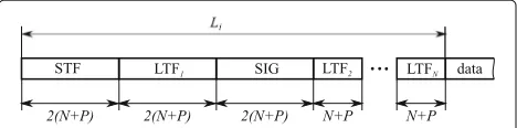
Specifically, the pilot sequence of streamk,k ∈[1,K], is repeatedly taken from thekth row of theK×Kdim. Walsh-Hadamard matrix,K =2,∈N. Figure 1 illustrates the data and pilot placement.
The composite data vectordk[n]∈ SkN of OFDM
sym-boln,n∈[1,Q], withQ Lu/(RNa) ,Lu/RmodNa =
0, is multiplexed with theN-point Fourier matrix F ∈
CN×N, fed into the permutation matrix
s∈B(N+P)×Nto add a cyclic prefix of lengthP, and sent over the channel. Without loss of generality, the relative propagation delays, caused by the channel, are incorporated in the channel impulse response (CIR). In receiverr, after analog-digital conversion the equivalent time-discrete observation vec-torζr[n]∈CN+Pis given by
whereT denotes the OFDM symbol time duration. The
Toeplitz channel matrixArk(τr) ∈ C(N+P)×(N+P) is
con-stituted of the static discrete-delay CIRαrk ∈CL,L≤ P.
The distortion matrixE(e) ∈ C(N+P)×(N+P)accounts for the frequency offset (FO) of the (common) local reference oscillator. It has the form
E(e)=diag[exp{−jφP} · · ·exp{jφ(N−1)}] (2)
with the phaseφ φ(e) =2πe/N, wheree=[−0.5, 0.5] is the FO normalized to subcarrier spacing. The matrix Tr(τr) ∈ B(N+P)×(N+P), containing the time offset (TO)
This TO is mainly caused by the signal buffers in the receiving USRPs. Finally, the entries of the vectorωr∈CN
are independent circularly symmetric Gaussian random variables with varianceσw2.
From (1), (2), and (3), the received unsynchronized time-discrete signal vector ζr[n], r = 1,. . .,NR, in
(1) is FO-corrected, fed into the permutation matrix Pr ∈ BN×(N+P) to remove the cyclic prefix, Fourier-transformed, and finally TO-corrected by the diagonal matrix D(τr) ∈ CN×N with the mth diagonal entry Dm,m(τˆr)=exp{j2πτr(m−1)/N},m=1,. . .,N, to yield
the frequency-discrete vector
yr[n]D(τr)FPrE(e)†ζr[n] , (4) r=1,. . .,NR.
2.1 Probabilistic model of the MIMO system
Suppose that exact estimations of the TO and FO are available at the receiver. Then, the signal vector in (4) simplifies to
denoting the truncated Fourier matrix, are samples of the frequency response of the channel between transmitterk and receiver r. For the design of the receiver, we make the assumption that the different channels are a priori mutually independent. Thus, we consider the prior pdf p(h11,. . .,hNRNT) =
NR r=1
NT
k=1p(hrk), where each
fac-tor is modeled as a complex Gaussian prior pdf with zero mean and covarianceph
m=
m
=
3
3
4
0
5
4
6
1
6
4
Fig. 1The placement of data symbols (diagonal stripes), pilots (filled), and unused carriers (empty) according to IEEE 802.11n (Na=52,Np=4,
N=64)
While the assumption we make does not model/take into account spatial correlation, it leads to lower plexity channel estimation [8]. We thus prefer low com-plexity over performance of the algorithm. In (5), the frequency-domain noise vectorwr has the pdfp(wr) =
CN(wr;0,λ−r1IN)withλr 1/N0being the noise preci-sion.
As design criterion, we use the bit-wise MAP decision rule, which minimizes the BER. That is, the decoded value of theith information bit of thekth stream is
ˆ
uk(i)= arg max uk(i)∈{0,1}
p(uk(i)|Y), (7)
wherep(uk(i)|Y)is the marginal posterior pdf of bituk(i)
and Y contains the observation vectors of all receive
antennas referring to all OFDM symbols of a packet:Y
{yr[n]|r∈[1,NR] ,n∈[1,Q]}.
The marginal posterior pdf required in (7) is computed from the joint posterior pdf of the variables in the proba-bilistic model of the system by marginalizing out all vari-ables but the bit of interest. Collecting all unknown system variables (channel responses, noise precision, data sym-bols, and information sequences) in , invoking Bayes’ rule and using the system assumptions, the joint posterior pdf writes
In the following, we introduce the notation for the fac-tors in (8) and give their functional form. We define the “observation” factors fYr to be the likelihood of the corresponding variables. From (5), we have
fYr(hr1,. . .,hrNT,d1[1] ,. . .,dNT[Q] ,λr)
The prior pdf of the precision of the noise at the rth receiver is denoted byf r. We choose a gamma prior pdf (i.e., a conjugate prior for the likelihood fYr) and set its parameters to be non-informative:
f r(λr)p(λr)
=Ga(λr; 0, 0).
For the prior pdf of the channel vector hrk, we write fHrk(hrk) p(hrk), with p(hrk) given by (6). The factor p(dk[1] ,. . .,dk[Q]|uk)is denoted by fCk and stands for the deterministic operations of coding, interleaving, and modulation mapping performed in transmitterk. Finally, fUk,i(uk(i)) p(uk(i))is the prior probability mass func-tion of theith information bit of transmitterk. We assume a uniform prior, i.e., the bit values are a priori equally probable.
It is helpful to visualize the probabilistic dependencies between the system variables by representing the factor-ization of the joint posterior pdf in a factor graph [3]. With the above definitions, the factor graph representing (8) is depicted in Fig. 2.
Fig. 2Factor graph representation of the pdf factorization in (8)
do not admit closed-formed expressions. That is, direct marginalization is computationally intractable. Therefore, we use an approximate inference framework to compute the estimates of the marginal pdfs of the variables, called beliefs. Then, the MAP decision in (7) will be applied to the beliefs b(uk(i)) ≈ p(uk(i)|Y) of the information
bits.
2.2 Physical layer convergence protocol
To facilitate synchronization and automatic gain control, a preamble of lengthLi symbols withLimodN = 0, is
prepended to each OFDM packet.
The preamble follows the IEEE 802.11n high-throughput (HT) greenfield format without a legacy compatible part, as sketched in Fig. 3. Notice that nei-ther coding nor scrambling is applied to generate the preamble.
The offset binary phase-shift keying (BPSK)-modulated short training field (STF) of thekth Tx antenna comprises a sequence of identical training symbols each of length
N/4, extending over two OFDM symbols [22] Section
20.3.9. The periodic structure of the STF is ideally suited for FO estimation. A subsequent BPSK-modulated first long training field (LTF), composed of two identical train-ing symbols each of lengthN, assists the receiver in esti-mating the TO and the CIR of the channel between the Tx antennakand Rx antennar. The following legacy signal
Fig. 3Greenfield preamble structure adopted from the IEEE 802.11n standard [22]
field (SIG) carries information on the HT packet format. AdditionalNT−1 high-throughput LTFs∈CNT(N+P)are
based on the same long training symbol as the first LTF in the preamble.
For the other Tx antennas k,k = k, cyclic shift is applied to the above preamble structure to prevent beam-forming when similar signals are transmitted on different spatial streams [22].
The receiver is unsynchronized and does not know the channel coefficients and the data sequences.
3 Test-bed setup and synchronization
We consider a NT × NR MIMO communication link
between one Tx node and one Rx node, comprising two host personal computers (PCs) andN=NT+NRUSRPs,
as illustrated in Fig. 4 forNT =NR=2.
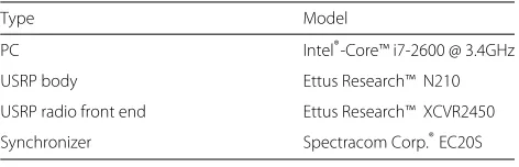
Each node was realized with the components given in Table 1. At hardware level of SDR, each USRP con-tains a bank of ADC/DACs, a wideband radio front end, and a vertical antenna. At software level of SDR, digital signal processing is distributed between internal field-programmable gate arrays (FPGA) and an external host PC.
The open source software framework GNU radio under GNU general public license (GPL) was adopted to real-ize the transceiver chain depicted in Fig. 4. The choice of GNU radio was motivated by its scalability, its flexibility in setting the signal processing components, and its wide user base.
Three different levels of synchronization are needed to realize MIMO communications on computer-hosted hardware: (i) synchronization of the USRPs; (ii) burst syn-chronization at sample level; (iii) synsyn-chronization of the CPU cores to process the individual data streams simulta-neously.
In the sequel, we describe how we addressed synchro-nization at each level.
3.1 USRP hardware synchronization
To enable MIMO communications, the transceiver must incorporate the following two functionalities: (i) each USRP hardware requires clock synchronization to derive the local oscillator frequency and timing synchroniza-tion to align the analog-to-digital converter/digital-to-analog converter (ADC/DAC) samples; (ii) all CPU cores have to align the digital signal streams in frequency [23] by the 10 MHz singleton and in time by the pulse-per-second (PPS) timing references. Our synchronizer, listed in Table 1, derives these references from GPS signals. In this way, PPS signals can be derived with an accuracy better than±50 ns.
Fig. 4A 2×2 MIMO-SDMA link with one transmitting node and one receiving node
3.2 PHY joint burst and carrier synchronization
3.2.1 Methodology
Given an observation of a random vectorZ specified by a family p(Z|θ) of pdfs parameterized byθ, the task is to compute an estimate of this parameter. The maximum likelihood (ML) point estimate ofθreads
ˆ
θ =arg max
θ p(Z|θ). (9)
Subsequently, we present a low-complex closed-form solution to joint ML time-offset and fractional frequency-offset estimation.
3.2.2 Synchronizer design
Let us return to the specific model in (1) withτrmodR=
0,r ∈[1,NR], whereRis the data rate. When two
subse-quent training symbols are identical, the received vector ζ[τr] at antennar,r∈[1,NR], and its time-shifted version ζ[τr+(N+P)T] are related by
ζ[τr+(N+P)T]=exp{j2πe(N+P)/N}ζ[τr] . (10)
To obtain a ML-based synchronizer that handles frame and frequency synchronization, one might choose the parameter vectorθ and observation vectorZ as, respec-tively, θ = {τ1,. . .,τNR,e} andZ = col{Z1,. . .,ZNR} withZrζ[τr+(N+P)T]−exp{j2πe(N+P)/N}ζ[τr].
The latter choice accounts for the time periodicity of the preamble. The synchronizer seeks to find the joint estimate
Table 1Hardware components constituting one node
Type Model
PC Intel®-Core™ i7-2600 @ 3.4GHz
USRP body Ettus Research™ N210
USRP radio front end Ettus Research™ XCVR2450
Synchronizer Spectracom Corp.®EC20S
{ ˆτ1,. . .,τˆNR,ˆe
ˆ
θ
} =arg max
θ logp(Z|θ ∈Rτ,e). (11)
Notice that the likelihood function in (11) exhibits a unique maximum in contrast to that in the work by [24].
A valid burst synchronization is achieved if θˆ is con-tained in the region
Rτ,e
τ1,. . .,τNR,e| NR
r=1
ζ[τr+(N+P)T]
= exp{j2πe(N+P)/N} NR
r=1 ζ[τr]
.
Due to the model assumptions, the log-likelihood func-tion in (11) reads
logp(Z|θ ∈Rτ,e)∝ −Z†−1Z2. (12)
The covariance matrix is given by = E{ωω†} =
N0I, whereIis the identity matrix. Expanding (12), we get
Z†−1Z2∝ NR
r=1
ζ[τr]2+ ζ[τr+(N+P)T]2
−2{exp{j2πe(N+P)/N}ζ[τr]† ζ[τr+(N+P)T]}.
(13)
The log-likelihood function in (12) can first be maxi-mized w.r.t.e, leading to
ˆ
e= − N
2π(N+P)T∠
N
R
r=1
ζ[τr]†ζ[τr+(N+P)T]
+I.
(14)
function in (12) can now be maximized w.r.t.τ1,. . .,τNR. Following this approach, we have
{ ˆτ1,. . .,τˆNR} =arg minτ
Inspecting (15), it can be seen that the TO of the rth receive stream is independent of the otherr−1 receive streams. As a result,
Substituting (16) into (14), yields
ˆ
The above burst synchronization algorithm is imple-mented in GNU radio software at the host PC. The resulting synchronized observation vector y[n,i] coly1[n,i]. . .yNR[n,i]
,n = 1,. . .,Q,i = 1,. . .,N (cf. (4)) is post-processed by MATLAB®.
3.3 Core synchronization
GNU radio 3.6.0 has an incorporated thread-per-block scheduler that allows for each signal processing block in the flow graph to run in an independent thread. The thread, associated to one block, loops until GNU radio code is terminated. In each loop, the thread calls the block’s executer. If the block has available output buffer and sufficient data in the input buffer, the execu-tor asks for signal processing on that block and then informs neighboring block(s) about its new status. Thus, all blocks in the flow graph process incoming data chunk-by-chunk [25].
4 Iterative channel estimation and data decoding In this section, we describe our proposed MIMO receiver algorithm, which recovers the information bits of the
K data streams. The various receiver tasks—channel
estimation, MIMO detection, and decoding—are jointly designed by formulating the bit recovery process as Bayesian inference on the probabilistic model of the underlying OFDM system. The resulting algorithm itera-tively computes and passes messages on the factor graph representing the probabilistic model. After a fixed number of iterations (tunable parameter), the algorithm returns the most probable configuration of the bits transmitted
in the K data streams, along with estimates of other
unknown quantities, such as the channel responses and the noise power.
4.1 Application to MIMO receiver design
The factor graph in Fig. 2 is split into the MF and BP parts by taking into account the functional forms of the factors and the specificities of the MF and BP algorithms. The factorsfYr,f r, and fHrk,r ∈[1,NR],k ∈[1,NT], and all variable nodes connected to them are placed in the MF part as they form a conjugate-exponential model. Given that BP has successfully been used for demapping and decoding, the rest of the factor nodes and the variable nodes connected to them represent the BP part.
4.1.1 Computation of messages and beliefs
The belief of each of the variables approximates the vari-able’s posterior pdf. In the forthcoming computations, the following statistics will occur:
(soft) estimate and uncertainty, respectively, of the symbol on thei th subcarrier of the nth OFDM symbol transmitted byk th antenna. Note that for pilot subcarriers (i.e.,i∈P), we have
ˆ
dk[n,i]=dk[n,i]andσd2k[n,i]=0.
• The mean and covariance matrix of the beliefb(hrk) of the respective vector of channel weights are denoted byhˆrk hrkb(hrk)and
the precision of therth receiver’s noise.
4.1.1.1 Channel estimation
Obtaining the beliefsb(hrk)≈p(hrk|Y),r∈[1,NR],k ∈
[1,NT] corresponds to channel estimation and requires
computing the MF messages related to the channel vec-tors. We readily show that the message from the observa-tion nodefYr has the Gaussian form
mMFf
represents the estimates and their uncertainty when
OFDM symbols and no prior information. Using the fact that multiplying Gaussian pdfs results in a Gaussian pdf, we obtain
and the diagonal matrixobsh
rk whose(i,i)th entry equals
with mean and covariance matrix
hrk =
4.1.1.2 Estimation of the noise precision
The message from the observation factor node mMFf
Yr→λr(λr)is found to be proportional to a gamma pdf. Given that the prior is a non-informative gamma pdf, the belief of the noise precision at receiver requals the messagemMFf
Yr→λr(λr). Therefore,
b(λr)=Ga(λr;QLd+1,βr), r∈[1,NR] , (19)
where the rate of the gamma pdf is given by
βr =
4.1.1.3 MIMO detection and decoding
The messages from the observation nodes are found to be
Note that the right-hand side of (20) is evaluated at the symbol constellation points. When normalized, those discrete messages “carry” extrinsic information on the different constellation points.
For alln∈[1,Q], the messagesNR
r=1mMFfYr→dk[n](dk[n]) are passed to the BP part. They represent the input to the demappers and decoders, which compute messages related to the coded bits and information bits using BP. For example, applying BP to decode convolutional codes is equivalent to using the BCJR algorithm [26]. The mes-sages mBPf
Ck→dk[n](
dk[n]), k ∈[1,NT], n ∈[1,Q] contain
extrinsic information on the respective symbols obtained from the decoders and soft mappers. The symbol beliefs
b(dk[n])∝
a posteriori probabilities (APPs) of the symbols. These values are further passed to the MF part.
The decoders also output the messages mBPf
Ck→uk[i]
(uk[i]),k ∈[1,NT] , i ∈[1,INk]. Given the prior pdfs, the beliefs of the information bits are obtained as
b(uk[i])∝mBPf
Ck→uk[i](uk[i])fUk,i(uk(i)).
4.1.2 Outline of the iterative algorithm
We now define the iterative algorithm by specifying a schedule for the message computations.
The BP-MF algorithm needs to be initialized. First, the algorithm sets the conditional expectations λˆr = QLd/Qn=1yr[n]2andhˆrk =0,k∈[1,NT],r∈[1,NR].
Then, the beliefs of those subvectors ofhrk,
correspond-ing to the pilot indicesP, are computed successively for eachk. Next,hˆobsrk [i]= 0 andσ−2
hobs
rk
[i]= 0, for alli ∈ D, and the beliefs of the channel vectors are computed as hrk, r ∈[1,NR], k ∈[1,NT]. Having obtained the initial
with the initial parameter settingdˆk[n,i]=0 and variance
σ2
dk[n,i]=1,k∈[1,NT],n∈[1,Q],i∈[1,INk]. The beliefs b(dk[n]), n ∈[1,Q] are computed sequentially for each k∈[1,NT], a scheme which resembles successive
interfer-ence cancelation. The initial stage ends with demapping and decoding.
During subsequent iterations, messages for soft map-ping, channel and noise precision estimation, MIMO detection, and demapping and decoding are computed.
After convergence, the information bits are determined by taking hard decisions based on the beliefsb(uk[i]),k∈
[1,NT],i∈[1,INk].
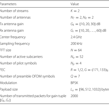
5 Performance evaluation in real environments The performance of the BP-MF iterative receiver was experimentally evaluated at some premises of the Isti-tutito di Informatica e Telematica (IIT) at the National Research Council (CNR), Pisa, Italy. The building is con-structed of concrete with steel reinforcement and with wooden doors. The measurements were conducted in the first floor in the Algorithms and Computational Mathe-matics laboratory of the institute. A map of this area is given in Fig. 5. Test cases include (i) a LOS link in an office environment, comprising the windows, office fur-niture, and computers and (ii) a non-LOS link, striking office rooms, bathrooms, and a corridor. Communication is based on the IEEE 802.11n standard for OFDM-MIMO [22]. The settings of the OFDM-SDMA system emulated on the test-bed are outlined in Table 2. The number of
counted error events per simulation point is large enough to produce sufficiently tight confidence intervals. Hence, the confidence intervals are omitted in subsequent plots.
The BP-MF receiver was benchmarked against a (low-complex) conventional MIMO receiver, composed of a linear MIMO channel filter using pilot-based channel esti-mates and a bank of individual ML-sequence decoders. Specifically, the MIMO channel estimate is based on the least squares technique given the Walsh-Hadamard pilot matrix and the synchronized observation matrix y. The composite MIMO channel estimates at all active tones,Hˆ, is obtained by piecewise linear interpolation. The decor-relating MIMO multiuser detector outputs the signal
ˆ
xHˆ−1y.
In real environments, the SNR at the individual slicer is unknown. To obtain a guess of the SNR, though, we use the following histogram techniques. Let
ˆ
γb,k[n] ˆ
σ2 b
Rσˆw2,k[n] (22)
be the packet-SNR estimate per uncoded bit of OFDM symbol n ∈[1,Q] with signal powerσˆb2 = ˆH−1H 1 and packet noise powerσˆw2,k[n]. For known transmission symbols, the latter quantity is Gamma-distributed with conditional expectation
5m
R
x1R
x2T
x1T
x2a
T
x1T
x2R
x1R
x2Table 2Parameter settings of the considered OFDM-SDMA
Number of active subcarriers Na=52
Number of pilot symbols Np=4
FEC R=1/2,G=(171, 133)8
Number of preamble OFDM symbols Q=7
Modulation BPSK
Payload size Lu= {96, 512, 1032}bytes
Number of transmitted packets for gain tuple
{Gk,Gr}
To construct a histogram fromγˆb,k, the data is split into
bins of width 0.5 dB. Each bin contains the number of occurrences of scores in the data set γˆb,k[n],n ∈[1,Q],
which fall within that bin. For the sake of fair comparison, both conventional MIMO and BP-MF receivers compute the SNR in the same way.
Experiments were conducted during nights or week-ends, to avoid as much as possible dynamic interference with employees’ movements and devices.
5.1 NLOS scenario
We first present the experimental results obtained in NLOS conditions. Without loss of generality, we focus on stream 1. Surprisingly, the BP-MF receiver was initially not able to decode the individual data streams at the out-put of the MIMO synchronizer (4) while it had done so in synthetic channels [8]. Closer examination revealed that the real channel is strongly correlated in space, a property that had not been accounted in the underlying channel model of the BP-MF receiver. When it is included in the system model, spatial channel correlation can be jointly estimated and exploited to improve the accuracy of the estimates of the other system parameters and vice versa [8]. As this estimation problem is outside the scope of the paper, spatial correlation is subsequently suppressed by an equalizer with transfer functionHˆ−1prior to MIMO reception. The same approach is pursued in the conven-tional MIMO receiver.
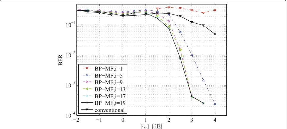
Figure 6 shows the bit-error rate (BER) vs. quantized packet-SNR per bit with the number of iterations i as a parameter. The payload size isLu = 512 bytes.
Inspect-ing Fig. 6, we see that with increasInspect-ing iteration indexi, the BER performance keeps improving until a minimum of the variational free energy is found. At the low and high SNR regimes, the BP-MF algorithm converges to a
fix-point around i i = 17 iterations. After
conver-gence, the proposed BP-MF outperforms the conventional receiver over the entire SNR range with a gain of up to 4 dB. This gain comes despite the mismatch between the real propagation conditions and those mimicked by the model used to derive the BP-MF algorithm.
The packet-error rate (PER) vs. [γˆb] with the number of iterations as a parameter is reported in Fig. 7 for a packet length ofLu = 512˙bytes. To achieve a typical target PER
of PER=0.1, the BP-MF algorithm requires [γˆb]≈2.1 dB after convergence. The conventional MIMO receiver, in contrast, meets the target-PER only at [γˆb]≈5.4 dB, leav-ing a gap of approximately 3.3 dB. The performance gap between the BP-MF and conventional MIMO receivers can be as high as 4 dB depending on the target PER value. With increasing payload size Lu, the BP-MF receiver
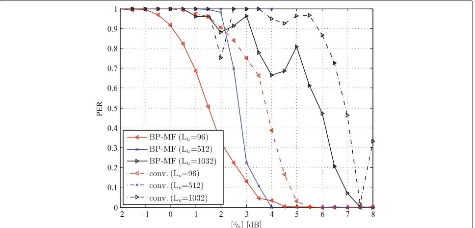
shows improved PER performance, as shown in Fig. 8. This is mainly because the individual bit errors are inde-pendent so that their impact on the packet-error rate is only 1 − (1 − BER)Lu. The target packet error-rate PER = 0.1 is met at [γˆb]≈ 1.9 (4.1) dB for Lu = 96
(Lu = 1032) bytes, corresponding to a SNR gap of 2.1 dB
for a tenfold increase in payload size. Also shown in Fig. 8, the (one-stage) conventional receiver, in contrast, has difficulties in handling large packet sizes.
5.2 LOS scenario
We now discuss the experimental results obtained in LOS conditions. From Fig. 9, it can be seen that the BER curve of the BP-MF receiver is confined in a
nar-row range around BER = 0.2 for small SNR values up
to [γˆb]= 2 dB, followed by a waterfall region for higher SNR values. Convergence is achieved after approximately i = 10 iterations. Generally speaking, the performance of the BP-MF receiver in the LOS condition is inferior to that in the NLOS condition, mainly because the num-ber of degrees of freedom of the channel that can be exploited by the receiver is higher in the latter condi-tion. The BP-MF receiver converges faster in LOS than it does in NLOS, because its convergence speed is inversely proportional to the number of degrees of freedom. The BP-MF receiver performs roughly 2 dB better than the conventional MIMO receiver over the entire SNR range.
Fig. 6BER performance of the BP-MF receiver in a NLOS condition for different values of the number of iterations (Lu=512 bytes)
the PER curve of the conventional MIMO receiver only starts decreasing towards zero beyond the SNR range of interest.
With increasing payload size, the PER performance of the BP-MF receiver still improves. However, the target of PER= 0.1 is met at [γˆb]≈3.1 (6.8) dB forLu =96 (Lu=
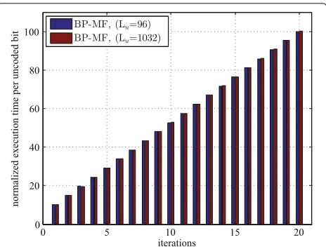
1032) bytes. The gap in SNR is now 3.7 dB (Fig. 11). Finally, Fig. 12 shows the execution time per uncoded bit of the BP-MF receiver normalized to the execution time by the conventional receiver. Payload sizes ofLu=96 and
Lu = 1032 bytes are considered. As the BP-MF receiver
operates at symbol level, its execution time is roughly independent of the payload size and, therefore, we con-clude that the per-bit computational complexity is linear in the payload size plus some offset. After the first iter-ation, the execution of the BP-MF algorithm has already required ten times more time than the execution of the conventional MIMO receiver. Ergo, the offset is ten. After convergence, typically ati =17 iterations, the ratio is as high as 87.
Fig. 8PER performance of the BP-MF receiver in a NLOS condition for different payload sizes (i=17 iterations)
6 Discussion and conclusions
In this paper, we investigated for the first time the trade-off between complexity, running time, and performance for an advanced, iterative MIMO-SDMA receiver operating in real world conditions. The receiver was derived within a unified message-passing framework that combines belief propagation and mean-field approxi-mation. At each iteration, messages related to the channel parameters and noise precision are passed from the mean
field part to the belief propagation part of the factor graph for the belief of the data and vice versa. The latter part represents the probabilistic model of the communica-tion system. The proposed receiver was implemented in USRP/GNU radio.
The study showed that while substantial performance improvements with respect to a conventional receiver can be achieved—ranging from 2 to 4 dB depending on packet size and LOS conditions—these benefits come
Fig. 10PER performance of the BP-MF receiver in a quasi-LOS condition with the number of iterations as parameter (Lu=512 bytes)
at an increase in per-bit decoding running time that increases linearly with the number of performed itera-tions. If full convergence (i.e., best performance) is sought, decoding running time can be as much as 2 orders of magnitude larger than that of a conventional receiver. However, substantial performance improvements can be
achieved also with a smaller number of iterations, espe-cially in a rich scattering environment (NLOS scenario). Summarizing, our study clearly shows that in practical settings the trade-off between receiver complexity, run-ning time, and performance should be carefully evaluated to strike the best compromise between these metrics.
Fig. 12Ratio of the execution time per uncoded bit of the BP-MF receiver to that of the conventional receiver
The results presented in this paper should be considered as a first step towards gaining an understanding of the feasibility of deploying advanced, iterative MIMO-SDMA receivers performance in real-world conditions. Future work includes considering higher-order modulations, as well as more complex MIMO configurations, including distributed MIMO channels.
Authors’ contributions
The paper presents a novel software radio implementation of a MIMO-SDMA receiver based on a recently developed unified message-passing framework. All authors read and approved the final manuscript.
Competing interests
The authors declare that they have no competing interests.
Author details
1Department of Computer Science, University of Pisa, Largo B. Pontecorvo 3,
56127 Pisa, Italy.2Department of Electronic Systems, Aalborg University,
Frederik Bajers Vej 7, 9220 Aalborg, Denmark.3Istituto di Informatica e
Telematica, National Research Council, Via G. Moruzzi 1, 56124 Pisa, Italy.
4SENSEable City Lab, Massachusetts Institute of Technology, 77 Massachusetts
Avenue, 02139 Cambridge, MA USA.
Received: 11 September 2015 Accepted: 6 December 2016
References
1. CM Bishop,Pattern Recognition and Machine Learning. (Springer, Secaucus, 2006)
2. J Pearl,Probabilistic Reasoning in Intelligent Systems: Networks of Plausible Inference. (Morgan Kaufmann Publishers Inc., San Francisco, 1988) 3. FR Kschischang, BJ Frey, H-A Loeliger, Factor graphs and the sum-product
algorithm. IEEE Trans. Inform. Theory.47(2), 498–519 (2001) 4. H-A Loeliger, J Dauwels, J Hu, S Korl, L Ping, FR Kschischang, The factor
graph approach to model-based signal processing. Proc. IEEE.95(6), 1295–1322 (2007). doi:10.1109/JPROC.2007.896497
5. M-A Badiu, GE Kirkelund, C Navarro Manchón, E Riegler, BH Fleury, inProc. IEEE Int. Symp. Inf. Th. (ISIT 2012). Message-passing algorithms for channel estimation and decoding using approximate inference, (Cambridge, 2012), pp. 2386–2390
6. J Winn, CM Bishop, Variational message passing. J. Mach. Learn. Res.6, 661–694 (2005)
7. E Riegler, GE Kirkelund, C Navarro Manchón, M-A Badiu, BH Fleury, Merging belief propagation and the mean field approximation: a free energy approach. IEEE Trans. Inform. Theory.59(1), 588–602 (2013) 8. C Navarro Manchón, GE Kirkelund, E Riegler, L Christensen, BH Fleury,
Receiver architectures for MIMO-OFDM based on a combined VMP-SP algorithm (2011). arXiv:1111.5848 [stat.ML]. http://arxiv.org/pdf/1111. 5848.pdf
9. M Dillinger, K Madani, N Alonistioti,Software Defined Radio: Architectures, Systems and Functions. (John Wiley & Sons, NJ, 2003)
10. H Yu, L Zhong, A Subharwal, D Kao, inProc. ACM Mobicom. Beamforming on mobile devices: a first study, (Las Vegas, 2011)
11. E Aryafar, N Anand, T Salonidis, E Knightly, inProc. ACM Mobicom. Design and experimental evaluation of multi-user beamforming in wireless lans, (Chicago, 2010)
12. K Tan, H Liu, J Fang, W Wang, J Zhang, M Chen, GM Voelker, inProc. ACM Mobicom. SAM: enabling practical spatial multiple access in wireless LAN, (Beijing, 2009)
13. K Mandke, S-H Choi, G Kim, R Grant, RC Daniels, W Kim, RWJ Heath, SM Nettles, inProc. IEEE 65th Vehicular Technology Conference
(VTC2007-Spring). Early results on Hydra: A flexible MAC/PHY multihop testbed, (Dublin, 2007), pp. 1896–1900
14. EttusResearch: http://www.ettus.com/. Accessed 14 Dec 2016 15. S Gollakota, SD Perli, D Katabi, inProc. ACM SIGCOMM. Interference
alignment and cancellation, (Barcelona, 2009), pp. 159–170 16. P Zetterberg, NN Moghadam, inSystems, Signals and Image Processing
(IWSSIP), 2012 19th International Conference On. An experimental investigation of SIMO, MIMO, interference-alignment (IA) and coordinated multi-point (CoMP), (Vienna, 2012), pp. 211–216 17. P Eliardsson, U Uppman, inProc. 7th Karlsruhe Workshop on Software
Radios (WSR’12). An SDR implementation of a MIMO communication testbed, (Karlsruhe, 2012)
18. WL Shen, YC Tung, KC Lee, KC Lin, S Gollakota, D Katabi, MS Chen, inProc. ACM Mobicom. Rate adaptation for 802.11 multiuser MIMO networks, (Istanbul, 2012)
19. KC Lin, S Gollakota, D Katabi, inProc. ACM SIGCOMM. Random access heterogeneous MIMO networks, (Toronto, 2011), pp. 146–157 20. T Wang, SC Liew, L You, inProc. of the 2014 ACM Workshop on Software
Radio Implementation Forum.SRIF ’14. Joint phase tracking and channel decoding for OFDM PNC: algorithm and experimental evaluation (ACM, New York, 2014), pp. 69–76. doi:10.1145/2627788.2627792
21. F Martelli, A Kocian, P Santi, V Gardellin, inProceedings of the 2014 ACM Software Radio Implementation Forum.SRIF ’14. MIMO-OFDM spatial multiplexing technique implementation for GNU radio (ACM, Chicago, 2014), pp. 85–92. doi:10.1145/2627788.2627795
22. IEEE 802.11-2012 (Clause 20), Wireless LAN Medium Access Control (MAC) and Physical Layer (PHY) Specifications (2012).
doi:10.1109/IEEESTD.2012.6178212
23. EttusResearch: Application note on synchronization and MIMO capability with USRP devices. http://www.ettus.com/content/files/kb/mimo_and_ sync_with_usrp_updated.pdf. Accessed 14 Dec 2016
24. A Saemi, V Meghadi, P-J Cances, MR Zahabi, Joint ML time-frequency synchronization and channel estimation algorithm for MIMO-OFDM systems. IET Circuits, Devices and Systems, 103–111 (2008). doi:10.1049/iet-cds:20070024
25. F Ge, C-YJ Chiang, Y Gottlieb, R Chadha, inProc. IEEE Global
Telecommunications Conference 2011 (GLOBECOM 2011). GNU radio-based digital communications: computational analysis of a GMSK transceiver, (Houston, 2011), pp. 1–6