Ghosna, Fadi and Sibley, Martin J.N.
Pulse position modulation coding schemes for optical intersatellite links
Original Citation
Ghosna, Fadi and Sibley, Martin J.N. (2007) Pulse position modulation coding schemes for optical
intersatellite links. In: Proceedings of Computing and Engineering Annual Researchers' Conference
2007: CEARC’07. University of Huddersfield, Huddersfield, pp. 112.
This version is available at http://eprints.hud.ac.uk/id/eprint/3703/
The University Repository is a digital collection of the research output of the
University, available on Open Access. Copyright and Moral Rights for the items
on this site are retained by the individual author and/or other copyright owners.
Users may access full items free of charge; copies of full text items generally
can be reproduced, displayed or performed and given to third parties in any
format or medium for personal research or study, educational or notforprofit
purposes without prior permission or charge, provided:
•
The authors, title and full bibliographic details is credited in any copy;
•
A hyperlink and/or URL is included for the original metadata page; and
•
The content is not changed in any way.
For more information, including our policy and submission procedure, please
contact the Repository Team at: [email protected].
PULSE POSITION MODULATION CODING
SCHEMES FOR OPTICAL INTERSATELLITE LINKS
F. Ghosna and M. J. N. Sibley
University of Huddersfield, Queensgate, Huddersfield HD1 3DH, UK
ABSTRACT
The rapid and significant development of communications links between satellites has made it possible to use various applications such as relay voice, video, multimedia, etc. As a result, a great deal of research has been done in this field during the last few years to reduce power consumption and increase transmission reliability.
This research project work is concerned with intersatellite links in free space, with optical links using laser sources being considered in particular. This paper discusses the use of several different coding schemes for use in such links: digital pulse position modulation (DPPM); multiple pulse position modulation (MPPM); Dicode pulse position modulation (Dicode PPM). A comparison is made using error rate performance and coding efficiency.
1 INTRODUCTION
A literature survey has been carried out in which the competing technologies of optical and microwave inter-satellite systems were examined by McCullagh et al (1993) & Ekberg (1970). These studies show that, in general, microwave radio systems can receive much lower power levels and operate in the atmosphere more efficiently than optical ones (McCullagh et al (1993)). However, optical systems can operate with much lower path loss and are considered superior to microwave ones in space (Ekberg (1970)). In addition, they have the potential of operation at Gbit/s data rates (McCullagh et al (1993)). Therefore, according to these considerations, optical links in space are receiving a great deal of attention.
At the receiver, a photodetector is needed to convert the modulated light signal back into an electrical one. There are two types of detector in use at present: avalanche photodiodes (APDs) or PIN photodiodes (Keiser (2000) & Sibley (1995)). The optimum choice depends on the wavelength of operation which, in turn, depends on how the laser source is to be modulated. In optical fibre communications, it is common practice to modulate a c.w. laser with an external Mach- Zehnder interferometer (Sibley (1995)). As these devices operate at a wavelength of 1.55 µm, this must be the wavelength of operation for the link. Therefore, work is currently being carried out to study the possibility of using a PIN photodiode with a semiconductor optical amplifier (SOA), or APD photodiode with SOA, and then select the best design for an inter-satellite link in free space at a speed of 1 Gbit/s.
2 CODING SCHEMES
According to Sibley (2004, December), digital PPM is the preferred coding scheme for use in optical inter-satellite links. This is because it operates with very low average power and offers high sensitivity. However, it does suffer from a very large bandwidth expansion problem in that a scheme coding 5 bits of PCM will have a final line rate of 6.4 times the original PCM rate (Sibley (2004, December)). This places great strain on the processing electronics and can be prohibitive.
The timing diagram of figure 1 shows examples of the MPPM, Dicode PPM and DPPM signals:
PCM
(3 BITS)
010
10010
MPPM
(5, 2)
001001
0000 0100
[image:4.595.65.534.189.483.2]Dicode PPM
DPPM
The coding alphabet for digital PPM and multiple PPM for 3 and 4 bits of PCM is shown in tables 1 and 2.
PCM (3 Bits)
DPPM
MPPM (5,2)
000
0000 0001
11000 (1,2)
001
0000 0010
10100 (1,3)
010
0000 0100
10010 (1,4)
011
0000 1000
10001 (1,5)
100
0001 0000
01100 (2,3)
101
0010 0000
01010 (2,4)
110
0100 0000
01001 (2,5)
[image:5.595.84.514.131.402.2]111
1000 0000
00110 (3,4)
Table 1. Alphabet for coding 3 bits of PCM into digital PPM and multiple PPM
As regards the coding alphabet, digital PPM codes n bits of PCM into a single pulse which occupies one of time slots. So, table 1 shows digital PPM in which a single pulse occupies one of 8 time slots to code 3 bits of PCM. However, multiple PPM scheme uses a number of pulses in a frame, with the pulse positions being determined by the original PCM word. Table 1 shows (5, 2) multiple PPM in which a 5-slot frame uses two data pulses to code 3 bits of PCM.
n
PCM (4 Bits)
DPPM
MPPM (7,2)
0000
0000 0000 0000 0001
1100000 (1,2)
0001
0000 0000 0000 0010
1010000 (1,3)
0010
0000 0000 0000 0100
1001000 (1,4)
0011
0000 0000 0000 1000
1000100 (1,5)
0100
0000 0000 0001 0000
1000010 (1,6)
0101
0000 0000 0010 0000
1000001 (1,7)
0110
0000 0000 0100 0000
0110000 (2,3)
0111
0000 0000 1000 0000
0101000 (2,4)
1000
0000 0001 0000 0000
0100100 (2,5)
1001
0000 0010 0000 0000
0100010 (2,6)
1010
0000 0100 0000 0000
0100001 (2,7)
1011
0000 1000 0000 0000
0011000 (3,4)
1100
0001 0000 0000 0000
0010100 (3,5)
1101
0010 0000 0000 0000
0010010 (3,6)
1110
0100 0000 0000 0000
0010001 (3,7)
[image:6.595.87.490.115.616.2]1111
1000 0000 0000 0000
0001100 (4,5)
Table 2. Alphabet for coding 4 bits of PCM into digital PPM and multiple PPM
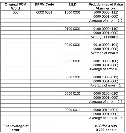
Work was carried out to show how the PCM error rate is affected by false alarm and erasure errors for digital, multiple and Dicode PPM operating with 3, 4, 5 and 6 bits of PCM.
A maximum likelihood sequence detector (MLSD) is used in the decoder and so the PCM error rate is stet as shown in tables 3, 4 and 5.
Original
PCM Word
MPPM Code
MLD
Probabilities of False
Alarm errors
000 11000
11100
01100
(100)
10100
(001)
11000
(000)
Average of error = 0.666
11010
01010
(101)
10010
(010)
11000
(000)
Average of error = 1
11001
01001
(110)
10001
(011)
11000
(000)
Average of error = 1.333
Final
average of
error
[image:7.595.86.496.168.472.2]0.999 for 3 bits
0.333 per bit
Table 3 Determination of PCM error when a false alarm occurs in (5,2) multiple PPM
Original PCM
Word
DPPM Code
MLD
Probabilities of False
Alarm errors
000
0000 0001
1000 0001 1000
0000
(111)
0000
0001
(000)
Average of error = 1.5
0100 0001
0100 0000 (110)
0000
0001
(000)
Average of error = 1
0010 0001
0010 0000 (101)
0000
0001
(000)
Average of error = 1
0001 0001
0001 0000 (100)
0000
0001
(000)
Average of error = 0.5
0000 1001
0000 1000 (011)
0000
0001
(000)
Average of error = 1
0000 0101
0000 0100 (010)
0000
0001
(000)
Average of error = 0.5
0000 0011
0000 0010 (001)
0000
0001
(000)
Average of error = 0.5
Final average of
error
[image:8.595.83.527.87.556.2]0.86 for 3 bits
0.286 per bit
Table 4 Determination of PCM error when a false alarm occurs in digital PPM
Original
PCM Word
MPPM Code
MLD
Probabilities of Erasure
errors
000 11000
01000
11000
(000)
01100
(100)
01010
(101)
01001
(110)
10000
11000
(000)
10100
(001)
10010
(010)
10001
(011)
Final
average of
error
[image:9.595.86.492.82.296.2]1.125 for 3 Bits
0.375 per bit
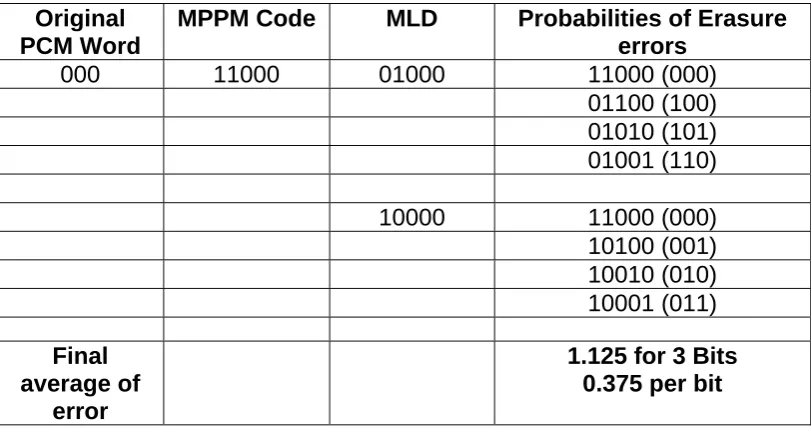
Table 5 Determination of PCM error when an erasure occurs in (5,2) multiple PPM
Taking the code 11000 MPPM, which is the code for 000 PCM, an erasure error leaves only one pulse in the detected code-word. As two pulses have to be present, the maximum likelihood sequence detector (MLSD) operates as shown in table 5.The same procedure applies if the second pulse is erased and the average error rate is obtained by taking each possible code-word in turn and averaging. Consideration of all possible code-words yields the total average erasure error as can be seen in table 6.
When a digital PPM pulse is erased, the decoded word is all zeroes. So the maximum likelihood decoder assumes it could have been any word at all. Thus the output word will be the average word – 111 (max) 000 (min) giving an average of 1.5 errors. For a 4 bit digital PPM word it would be 1111 (max) 0000 (min) average of 2 errors, etc.
3 RESULTS AND DISCUSSION
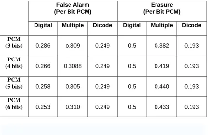
Table 6 shows how the PCM error rate is affected by false alarms and erasures for digital, multiple and dicode PPM operating with 3, 4, 5 and 6 bits of PCM.
False Alarm
(Per Bit PCM)
Erasure
(Per Bit PCM)
Digital
Multiple
Dicode
Digital
Multiple
Dicode
PCM
(3 bits)
0.286
o.309
0.249
0.5
0.382
0.193
PCM
(4 bits)
0.266
0.3088
0.249
0.5
0.419
0.193
PCM
(5 bits)
0.258
0.305
0.249
0.5
0.440
0.193
PCM
(6 bits)
0.253
0.310
0.249
0.5
0.433
0.193
Table 6 Summary of PCM errors caused by false alarm and erasures in digital, multiple and dicode PPM
As can be seen, dicode PPM is the best coding scheme in terms of error rate because it has the lowest false alarm and erasure error rates. In addition, digital PPM is better than multiple PPM in terms of false alarm error rate because it has fewer errors than multiple PPM. Multiple PPM is better than digital PPM in terms of erasure error rate. However, this data neglects the effects of bandwidth expansion and power efficiency in terms of photons per pulse and average power.
4 CONCLUSION
Digital PPM coding can operate with very low average power and offer a high sensitivity, thus it is the preferred choice for optical inter-satellite links. However, it does suffer from a very large bandwidth expansion problem. Many alternative schemes have been proposed such as differential PPM, overlapping PPM, dicode PPM and multiple PPM. The most bandwidth-efficient of these are dicode PPM and multiple PPM.
REFERENCES
Atkin, G.E., and Fung, K.-S.:’ Coded multipulse modulation in optical communication systems’, IEEE Trans. Commun., 1994, 42, (2/3/4), pp. 574-582
Ekberg, J. (1970, 6 April).Transmission Calculations for Infrared-Optical Links. Helsinki, Finland: The STATE Institute for Technical Research.
Japan Aerospace Exploration Agency (JAXA). (2006, November). “Kirari” Optical Inter-Orbit Communications Engineering Test Satellite (OICETS). Retrieved November 16, 2006, from
http://www.jaxa.jp/missions/projects/sat/tsushin/oicets/index_e.html
Keiser, G. (2000). Optical Fibre Communications (3rd Ed). McGraw-Hill Higher Education: McGraw-Hill Companies, Inc.
Lutz, H.P. (1997, August). Optical Communications in Space - Twenty Years of ESA Effort. ESA Bulletin Nr.91. Retrieved November 21, 2006, from
http://www.esa.int/esapub/bulletin/bullet91/b91lutz.htm
McCullagh , M. J., Wisely, D.R., Mobility Group, SRD. (1993, 14 October).A Comparison of Microwave and Optical Free Space point to Point links. Revision: Issue 1, QA status: Reviewed, Project: 1634 Job 00.
Park, H., and Barry, J.R.: ‘Modulation analysis for wireless infrared communications’. Proc. IEEE Int. Conf. on communications, 1995, pp. 1182-1186
Park, H., and Barry, J.R.: ’Performance analysis and channel capacity for multiple-pulse position modulation on multipath channels’. Proc. IEEE Int. Symp. On Personal, Indoor and Mobile radio communications, 1996, pp. 247-251
Park, H., and Barry, J.R.: ‘Partial-response precoding scheme for multiple pulse-position modulation’, IEE Proc., Optoelectron, 2003,150, (2), pp. 133-137
Shalaby, H.M.H.: ’A performance analysis of optical overlapping PPM-CDMA communication systems’, IEEE J. Lightw. Technol., 1999, 17, (3), pp. 426-434
Shiu, D.S., and Kahn, J.M.: ’Differential pulse-position modulation for power-efficient optical communication’, IEEE Trans. Commun., 1999, 47, (8), pp. 1201-1210
Sibley, M. J. N. (1995). Optical Communications (2nd Ed). Houndmills, Basingstoke, Hampshire RG21 2 XS, and London: The Macmillan Press LTD.
Sibley, M.J.N.: ‘Dicode pulse position modulation – a novel coding scheme for optical fibre communications’, IEE Proc., Optoelectron., 2003, 150, (2), pp. 125-131
Sibley, M.J.N.: ’Sub-optimal filtering in a zero guard, dicode PPM system operating over dispersive optical channels’, IEE Proc., Optoelectron., 2004, 151, pp. 237-243
Sibley, M. (2004, December). Analysis of multiple pulse position modulation when operating over graded-index plastic optical fiber. IEE proc –Optoelectron., Vol. 151 , No. 6, December 2004 .
Sugiyama, H., and Nosu, K.: ‘MPPM: A method for improving the band-utilization efficiency in optical PPM’, IEEE J. Lightw. Technol., 1989, 7, (3), pp. 465-472