R E S E A R C H
Open Access
An improved k-NN algorithm for localization in
multipath environments
Yang Zhao, Kaihua Liu, Yongtao Ma
*and Zhuo Li
Abstract
To improve the localization accuracy in multipath environments, this paper presents an effective localization approach with the utilization of reference tags. In this approach, an improved k-nearest neighbor (k-NN) algorithm is proposed based on radio-frequency (RF) phases. The traditional k-NN algorithm only focuses on the weighting factors of the coordinates of the selected reference tags, while the improved k-NN algorithm aims at the estimation of direct distance from a reader antenna to a target tag. Then, the location is estimated by linear least squares with a new reference selection scheme. Simulation results show that our approach is superior to the traditional
localization approaches under multipath environments. In addition, we conclude that phase has the superiority over strength in the selection of reference tags for range estimation, and range estimation is more accurate than coordinate estimation with k-NN algorithm for localization.
Keywords: Indoor environments; RF phase; Reference tags; Improved k-nearest neighbor algorithm;
Linear least squares
1 Introduction
Indoor location awareness is a hot research subject in many wireless systems due to its capability to provide a wide range of location-based services. Due to the multi-path propagation channel in indoor environments, it is hard to achieve a high accuracy in localization which is urgently needed for both commercial and industrial in-terests. Many technologies and systems have been devel-oped for indoor localization, and one of the most popular technologies is the ultrahigh frequency (UHF) radio-frequency identification (RFID) technology. UHF RFID signals can be active or passive based on whether the RFID tag has an internal source of energy or not. In this paper, we focus on passive RFID tags for their less cost, long lifetime, and maintenance-free characteristics.
Existing range measurement techniques for RFID-based application include the time of arrival (TOA) technique [1-4], the time difference of arrival (TDOA) technique [5,6], the phase of arrival (POA) technique [7-13], and the received signal strength indicators (RSSI) technique [14,15]. The TOA technique measures the one-way propa-gation time, and the distance between the transmitter and
the receiver can be calculated using the propagation velocity of the signal. But, a precise synchronization of all transmitters and receivers is required to guarantee the cor-rect localization estimation. The TDOA technique does not require the synchronization of the transmitter and receiver and uses the time difference of a transmitted signal at the receivers, so it requires that the reference receiver sub-tracted be precise. The POA technique can measure the complete propagation distance of the signal between a transmitter and receiver but has a problem of having whole-cycle phase ambiguities in the calculation. The RSSI technique uses the attenuation of the sent signal to estimate the distance between the transmitter and the receiver. Though this technique is less complex than other tech-niques, it suffers from poor accuracy because the signal strength can be easily affected by various environment fac-tors, such as multipath. So, the impact of the wireless chan-nel on the received signals [16] is significant. In a radar sensor network, information diversity has been utilized for the improvement of detection accuracy [17-19] and reliable communications [20]. Based on the above-mentioned range measurement techniques, the target location can be esti-mated by using the geometric properties of triangles [21].
Due to the inadequate accuracy of range measurement techniques, localization algorithms using scene analysis * Correspondence:[email protected]
School of Electronic Information Engineering, Tianjin University, Tianjin 300072, China
is developed to improve the overall accuracy. As an ef-fective scene analysis localization algorithm, the k-nearest neighbor (k-NN) [22] algorithm is proposed by utilizing reference tags. This algorithm estimates the tar-get localization by using the coordinates of the reference tags which are closest to the target tag with RSSI Euclidean distances. Since severe multipath and interference effects can easily affect signal strength, a distant reference may be selected as the candidate tag, significantly lowering the localization accuracy [23]. Even so, strength is still com-monly used in scene analysis algorithm. In recent years, another way to compute the location is proposed by es-timating the distance from a reader antenna to the tar-get tag with the help of selected reference tags just as range measurement techniques do [24-26]. Therefore, we consider that a similar measurement value means a similar distance between a pair of tag-and-reader an-tenna, not only the closest coordinate position in space.
In this paper, we propose an indoor localization ap-proach following the concept of reference tags in the k-NN algorithm which is a further study on the localization approach proposed in [24]. We substitute phase for strength in the Euclidean distance calculation just as the approach proposed in [24]; however, we make a lot of improvement.
This paper is organized as follows. In Section 2, the radio-frequency (RF) phase is measured with a single-frequency subcarrier amplitude modulation. In Section 3, an improved k-NN algorithm is proposed to estimate the direct distance between a reader antenna and the target tag, and the localization is estimated by linear least squares algorithm with a new reference selection scheme. Simulative results are illustrated in Section 4, and the improvement in localization accuracy is shown to prove the effectiveness of the proposed approach. In the end, the conclusion is presented in Section 5.
2 RF Phase
Assuming that all reader antennas emit pure cosine sig-nals, we can utilize the phase of arrival technique to meas-ure distance which does not exceed half of the signal wavelength. Since the UHF RFID signal wavelength is tens of centimeters, the actual distance is a few meters or even dozens of meters between a reader and a tag. So, if we utilize the extracted phases of UHF RFID signals directly, there will be a whole-cycle carrier phase ambiguities prob-lem in distance estimation. To avoid this probprob-lem, we should use a low-frequency signal with a longer wave-length to measure the phase accumulated during the sig-nal travel from the reader to the tag and back.
2.1 Traditional RF-phase-based ranging algorithm
For the purpose of eliminating the whole-cycle carrier phase ambiguities, the frequency of the signal for phase
extraction should be low. In other words, the round trip distance should be shorter than the wavelength of the signal. Meanwhile, we also need an extra energy signal to start up the passive tag. In summary, we should use a low-frequency signal to measure the phases and a high-frequency signal to support energy simultaneously in the whole communication process. With the concept of sub-carrier amplitude modulation in [27], we utilize a single-frequency subcarrier in the communication process, where the low-frequency signal is taken as the subcarrier signal and the high-frequency signal is the carrier signal. The transmitted signal is expressed as Equation 1 and the received signal expressed as Equation 2.
s nð Þ ¼A½1þmacosðωstþφsÞcosðωctþθsÞ ð1Þ
r nð Þ ¼A0m tð Þ½1þmacosðωstþφrÞ cosðωctþθrÞ þn tð Þ
ð2Þ where ωs stands for the angular frequency of the sub-carrier; φs is the original phase of the subcarrier; ωc stands for the angular frequency of the carrier;θs is the original phase of the carrier; A and A′ are the ampli-tudes of the carrier in transmitting and receiving, re-spectively; madenotes the modulation index; and n(t) is the addictive noise of the wireless channel.φrand θrare the phases of the received subcarrier and the carrier, re-spectively.m(t) is the baseband signal of the tag.
The zero-IF scheme is a way to realize the down con-version of the received signal. This scheme needs neither modification of the current structure of the RFID readers nor extra hardware, which reduces the cost to a great extent than the sub-Nyquist sampling used in [24]. In this scheme, the received signalr(n) will be converted in an in-phase/quadrature (I/Q) demodulator, which splits the received signal into two parts by mixing it with the local oscillator signal cos(ωct +φ) and the local
oscil-lator signal shift by 90°, respectively, as in Equations 3 and 4.
rIð Þ ¼t r tð ÞcosðωctþφÞ ð3Þ
rQð Þ ¼t r tð ÞsinðωctþφÞ ð4Þ
The twoIand Qcomponent signals are filtered to re-move the high-frequency signal components, leaving be-hind the subcarrier signal containing the phase of signal as in Equations 5 and 6. Then, we use the sampling fre-quency fs to sample the signals and extract the
sub-carrier phase information in the digital domain with the all-phase FFT [28].
I tð Þ ¼A
0
2m tð ÞmacosðωstþφrÞcosðθr−ϕÞ
Q tð Þ ¼−A
0
2m tð ÞmacosðωstþφrÞsinðθr−ϕÞ
þN tð ÞsinðωctþϕÞ ð6Þ
So, the subcarrier phase information extracted can be expressed as
φ¼φr−φs ð7Þ
In the end, the calculated propagation distance can be written as
d∧¼ cφ
2ωs ð
8Þ
where c is the speed of the electromagnetic wave
propagation.
2.2 RF Phase analysis
As we know, the phase of the received signal in real propagation environments can be expressed as
φ¼φpropþφmþφoþφb ð9Þ
where φprop stands for the phase accumulated during the round direct trip between a reader antenna and a tag antenna; φm is the phase offset of the multipath effect and the reflection from the obstacles; φo represents phase shifts of the reader and antenna components, as well as cables; and φbis the backscattered phase of the tag modulation [29].
For accurate localization estimation, we should only extract the φpropcomponent for distance calculation in
Equation 10. As the other phase error components can-not be eliminated completely, the exact phase for meas-uring propagation distance is a tough task.
d¼cφprop
2ωs ð
10Þ
In our paper, we introduce the reference tags just like [22,26] but substitute phase for strength in the re-ference tag selection. The positions of rere-ference tags and reader antennas are known beforehand which means that the direct distance between them can be calculated directly. As the reference tags are involved in the same environment as the tags to be located, the direct distances between them can be used to improve localization accuracy.
3 Localization approach 3.1 Traditional k-NN algorithm
The LocAtioN iDentification based on dynaMic Active Rfid Calibration (LANDMARC) [22] system uses the k-NN algorithm with reference tags to estimate the locations of target tags. Let Nbe the number of reader antennas and M be the number of reference tags. The
signal strength vector of theith target tag is defined as TSi= (ts(i,1), ts(i,2),…, ts(i,N)) where ts(i,j)denotes the
sig-nal strength of the ith target tag perceived by the jth reader antenna, where j∈(1,N). For themth reference tag, the corresponding strength vector is RSm= (rs(m,1),
rs(m,2),…, rs(m,N)). The Euclidean distance in signal
strength between the ith target tag and mth reference tag is defined as
So theith target tag has its strength Euclidean distance vectoreias
ei¼eð Þi;1;eð Þi;2;…;eði;MÞ ð12Þ
After sorting ei in ascending order, the vector can be defined as
Ei¼ Eð Þi;1;Eð Þi;2;…;Eði;MÞ
ð13Þ
Then, according to the k-NN algorithm, the first
K values can make a new Euclidean distance vector
Ei= (E(i,1), E(i,2),…, E(i,K)). The weighting factor for each
selected reference tag can be calculated by
ωð Þi;k ¼
In the last, the estimated location of the ith target tag is given by
iÞ is the estimated coordinate of the ith target tag, and (xk,yk, zk) denotes the coordinate of the kth selected reference tag.
3.2 Phase-based improved k-NN algorithm
In this paper, we propose a phase-based improved k-NN algorithm (Phase (improved k-NN)). The phase vector of the ith target tag is defined as TP = (tp(i,1), tp(i,2),…,
tp(i,N)), where tp(i,j)denotes the phase of the ith target
tag perceived by thejth reader antenna, wherej∈(1,N). And, we define the phase of the reference tags perceived by thejth reader antenna as RPj= (rp(1,j), rp(2,j),…, rp(M,j)),
where rp(m,j)denotes the phase of the mth reference tag
epðm;jÞ¼abs tp ð Þi;j−rpðm;jÞ ð16Þ
An important difference in our algorithm is that we se-lect the Knearest reference tags by calculating the differ-ence between the target tag and the referdiffer-ence tags about each one of the reader antennas as Equation 16, not the sum of all those reader antennas as Equation 11. So, the phase Euclidean distance vector epjabout thejth reader an-tenna is defined as epj= (ep(1,j), ep(2,j),…, ep(M,j)). We also
sort epjin ascending order and select the firstKvalues, i.e., EPj= (EP(1,j), EP(2,j),…, EP(K,j)). As we know, the noise is
ran-dom, we repeat the above calculation for Q times and record the selected reference tag numbers and its corre-sponding EP(k,j)each time. Then, we get a list of the
num-ber of the selected reference tag and calculate the frequency of selection for each reference tag number, then select the firstKreference tags with the highest frequency as the final selected reference tags, i.e.,f1,f2,…,fK. Meanwhile, we com-pute the averaged phase Euclidean distance of these se-lected reference tags, i.e., ave_EP(k,j). The weighting factor
for each neighboring reference tag is calculated by
ωð Þk;j ¼XKfkaveEPð ÞK;j
k¼1
fkaveEPð ÞK;j
ð17Þ
When we get the weighting factor for each selected reference tag, we use these weighting factors to estimate
the direct distance dj ∧
between ith target tag and the jth reader antenna.
dj∧ ¼X K
k¼1
ωð Þk;jRdð Þk;j ð18Þ
where Rd(k,j)is the direct distance between kth selected reference tag and thejth reader antenna, and as the ref-erence tags are fixed, Rd(k,j)is known beforehand. And, the ranging error is given by
ed¼
wheredjis the real distance of the target tag.
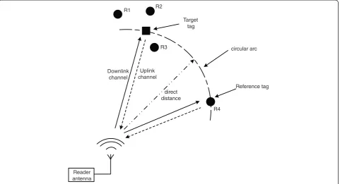
The reason that we prefer the direct distance between the reader antenna and reference tags to the coordinate of the reference tags can be explained in Figure 1. We utilize one reader antenna as an example; the transmit-ted signal is sent via the downlink channel (marked as a solid line) to the tag and returned over the uplink chan-nel (marked as a dotted line). The square stands for the target tag and the triangles (R1, R2, R3, and R4) stand for the reference tags. As the R1, R2, and R3 reference tags are surrounding the target tag, they are likely to
have some similarities in the measurement informations. Reference R4 has the same direct distance as the target tag from the reader antenna. In multipath propagation environments, the measurement of reference R4 may also be similar with the target tag. If we set the kvalue in the k-NN algorithm as 4, the selected reference tags will be R1, R2, R3, and R4. If we still use the coordinates of the selected tags, the localization will be estimated with considerable error. On the contrary, their direct distances are approximately equal. So, we think range es-timation is more appropriate for localization than co-ordinate estimation.
3.3 Localization algorithm
The distancedjbetweenith target tag and thejth reader antenna defines a spherical surface around thejth reader antenna, and the localization equation is nonlinear as Equation 19. jth reader antenna localization. We can make Equation 20 linear by fixing the expression of therth reader antenna, i.e., the reference reader antenna, subtracting it from the rest of the equations. As for the selection of therth reader antenna, we propose a reference reader antenna selection scheme. Firstly, we calculate the distance rd(m,j)between themth reference tag andjth reader antenna by Equation8 with theQ-averaged reference tag phases. Next, we com-pute the estimation error of each reader antenna as
rdj¼X
The one with the least estimation error is marked as the rth reader antenna. Then, we can get the final localization of the ith target tag by utilizing the linear least squares (LLS) algorithm. In [30], the reference selection is given by comparing the distances from the target tag to reader antennas, so we name it LLS-RS-TT.
r¼ arg min
In the end, the location estimation erroreiis given by
ei¼
ffiffiffiffiffiffiffiffiffiffiffiffiffiffiffiffiffiffiffiffiffiffiffiffiffiffiffiffiffiffiffiffiffiffiffiffiffiffiffiffiffiffiffiffiffiffiffiffiffiffiffiffiffiffiffiffiffiffi
^ xi−xi
ð Þ2þ ^
yi−yi
ð Þ2þ ^
zi−zi
ð Þ2
q
ð23Þ
where ðx∧i;y∧i;z
∧
iÞ and (xi,yi, zi) denote the estimated co-ordinate and the real coco-ordinate of the ith target tag, respectively.
3.4 Comparison with other localization approaches
To investigate the performance of the approach Phase (improved k-NN) + LLS-RS-RT proposed in our paper, we simulate some other localization approaches in the same scenario of this paper. These comparison approaches are as follows:
1) Strength (k-NN): It is processed just as the LANDMARC [17] system is processed. And for comparison, the localization results of this approach are averaged forQtimes, as we can get a result per simulation time during theQtimes.
2) Phase (k-NN): It has the same procedure of Strength (k-NN), but it utilizes the phase instead of the strength of the signals to compute the Euclidean distance. The final results are averaged forQtimes.
3) Strength (improved k-NN) + LLS-RS-TT: It calculates the strength Euclidean distance by Equation16like calculating the phase Euclidean distance and estimates the direct distances from reader antennas and the
target tag by Equations17and18. Location is estimated by LLS-RS-TT.
4) Phase (1-NN) + LLS-RS-TT: In [24], we use the 1-nearest neighbor (1-NN) to estimate the direct distance from the target tag to the reader antenna and utilize LLS-RS-TT to calculate the location. For comparison, we average the localization results of each target tag forQtimes.
5) Multi-frequency + LLS-RS-TT: Here we use the method FM2 with multi-frequency in [31] to calculate the tag distance and estimate the location by LLS-RS-TT.
6) Phase (improved k-NN) + LLS-RS-TT: It has the same ranging procedure of Phase (improved k-NN) + RT except the location is estimated by LLS-RS-TT.
4 Simulation
We evaluate the performance of Phase (improved k-NN) + LLS-RS-RT and compare it with the other five ap-proaches explained in Section 3.4. It indicates that our approach can improve the accuracy significantly under multipath environments and is superior to the other approaches.
4.1 Simulation setup
These simulations are implemented in MATLAB lan-guage and tested on a PC with an Intel Core i3-3220 CPU of 3.30 GHz and DDR3 SDRAM of 4 GB. Here, we
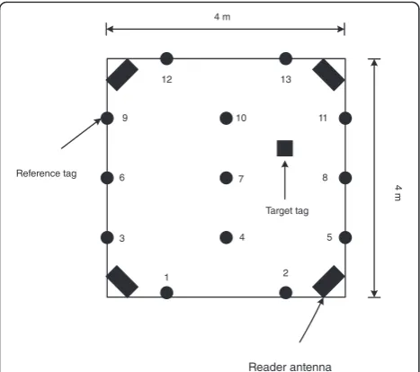
use eight reader antennas placed around the eight cor-ners of an indoor scene which is modeled in a space of 4 × 4 × 4 m3. As for the reference tags, we choose 13 refer-ence tags which are numbered and arranged as Figure 2, with a height of 2 m. The carrier frequency is 910 MHz, and the subcarrier frequency is 2 MHz. TheQvalue in the improved k-NN algorithm is 100, and theKvalue is set to 4 as a matter of experience. We set 1,000 target tags randomly in the scenario and each with a height of 2 m for space average. Because theQfactor used in the improved k-NN algorithm is like some kind of time average, we should also simulate the comparison ap-proaches without using the improved k-NN algorithm for Qtimes and average the results for comparison. In this paper, the root mean square error (RMSE) evalu-ation factor is used as the rule of localizevalu-ation accuracy. And, we express it as
RMSE¼
ffiffiffiffiffiffiffiffiffiffiffiffiffiffiffiffiffiffiffiffiffiffiffiffiffiffiffiffiffiffiffiffiffiffiffiffiffiffiffiffiffiffiffiffiffiffiffiffiffiffiffiffiffiffiffiffiffiffiffiffiffiffiffiffiffi
E ð^xi−xiÞ2þð^yi−yiÞ
2þ ^
zi−zi ð Þ2
q
ð24Þ
where E denotes the averaging operator for the 1,000
target tags, ðx∧i;y∧i;z
∧
iÞ denotes the averaged estimated position of the ith tag for Q iterations, and (xi, yi, z) denotes the real position of theith tag. So, in our simu-lation, RMSE is the average value in both space and time. The smaller the value of RMSE is, the higher the localization accuracy is.
The RFID channel contains a downlink channel and an uplink channel at one time. In our simulation, each of these two channels is modeled as a linear time variant fil-ter channel. The corresponding channel pulse response is
h tð Þ ¼alos⋅δðt−τlosÞ þ
XP
i¼1
anlos;i⋅δ t−τnlos;i
ð25Þ
contains a direct line-of-sight (LOS) path with a time delay of τlosand path gain of alosand a sum of P
non-line-of-sight (NLOS) paths of delay τnlos,i and path gain ofanlos,i. The path gain is modeled by path-loss and log-normal shadowing, and the expressions of reflection co-efficients in [32] are also considered for the calculation of path gain of each NLOS path. Then, the complex path gain model of the deterministic multipath channel be-tween the reader and the tag is given by [8]. Here, we suppose there are four propagation paths under the mul-tipath environment, including the direct ray, the two wall reflection paths, and the ground reflection path, as shown in Figure 3. For simplicity, we just consider the case that the signal propagates back just as the way it sends. Thus, the received RF signal can be expressed
y tð Þ ¼x tð Þ⊗hdð Þt ⊗huð Þ þt n tð Þ ð26Þ
wherex(t) denotes the sending signals andhdand huare channel pulse responses of downlink and uplink chan-nels, respectively, and are equal in our simulation.n(t) is the additive Gaussian noise.
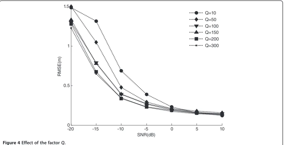
4.2 Effect of the factorQ
In our approach, the location of each target tag is esti-mated by Qiterations. So,Q is a key factor for the im-provement of performance in localization. But, the number of iterations will directly influence the running time of calculation. So, we should make a compromise between the accuracy and the time complexity. Figure 4
Figure 2The arrangement of reference tags from the top view.
shows the accuracy comparison between different Q
values. From the simulation results, we find that the loca-tion estimaloca-tion error will decrease with the increase of the
Qvalue. But when theQvalue is larger than 100, there is no obvious increase in accuracy. So, 100 is an appropriate value for factorQin our following simulations.
4.3 Ranging accuracy
In this section, the averaged ranging error is calculated by averaging the errors of all target tags. Figure 5 shows the ranging performance comparison between different approaches. From the figure, we can see that our algo-rithm is superior to the other three approaches. When the signal-to-noise ratio (SNR) value is−20 dB, the error of Phase (improved k-NN) is almost the same as the re-sult of Strength (improved k-NN), but our algorithm is much better under higher SNR values. The results indi-cate that phase is an excellent measurement indicator for range estimation in k-NN algorithm.
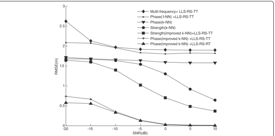
4.4 Localization accuracy
In this section, averaged location estimation error is shown as the RMSE changing with the SNR values. As shown in Figure 6, the performance of the Multi-frequency + LLS-RS-TT is the worst than other approaches under low SNR values. Phase (1-NN) + LLS-RS-TT does not improve the accuracy effectively when the SNR value increases, so the ranging procedure needs to be revised. Phase (k-NN) and Strength (k-NN) have the same perform-ance when the SNR value is low, but Strength (k-NN) works much better than Phase (k-NN) in higher SNR
values. So, we can conclude that strength is more suitable for non-ranging algorithms than phase. Strength (improved k-NN) + LLS-RS-TT is better than the above four ap-proaches but it is still worse than Phase (improved k-NN) + LLS-RS-RT and Phase (improved k-NN) + LLS-RS-TT. It means that phase has the superiority over strength in the selection of the reference tags for range measurement, and range estimation is more accurate than coordinate estima-tion with k-NN algorithm for localizaestima-tion. The accuracy of Phase (improved k-NN) + LLS-RS-RT is superior to Phase (improved k-NN) + LLS-RS-TT under low SNR environ-ments and almost equal when the SNR is higher. So, we think LLS-RS-RT is a better reference selection scheme in LLS algorithm with reference tags, and LLS-RS-TT is also an effective selection criterion in approaches without refer-ence tags. In addition, the localization accuracy of our ap-proach does not change so obviously among the range of the SNR values. So, our approach is robust to environment interferences.
Figure 7 illustrates the cumulative distribution func-tion (CDF) of the localizafunc-tion accuracy for different ap-proaches under two different SNR values. Figure 7a shows the CDF results when the SNR is −20 dB. Based on the statistics, it can be seen that the 80 percentile has a localization estimation error under 0.78 m and the 90 percentile is under 0.90 m in Phase (improved k-NN) + LLS-RS-RT which is the approach proposed in our paper. The performance of Phase (improved k-NN) + LLS-RS-TT is 0.93 and 1.04 m, respectively. Then, the results of the other approaches are much more than 1 m corresponding to the two percentiles. Figure 7b illustrates
the corresponding results when the SNR is 0 dB. The curves of the CDF for Phase (improved k-NN) + LLS-RS-RT and Phase (improved k-NN) + LLS-RS-TT overlap al-most completely. With the improvement of the SNR value, the difference between the other approaches is more obvi-ous. The error range of Phase (k-NN) is between 0.44 and 2.87 m. We think phase is more appropriate for ranging algorithms.
4.5 Cost analysis
We analyze the cost of different approaches compared in our paper. From the description of each approach, we know that Phase (improved k-NN) + LLS-RS-RT, Phase (improved k-NN) + LLS-RS-TT, and Strength (improved k-NN) + LLS-RS-TT all finish the location estimation of each target tag after Q iterations, while the other approaches can get the final results at one
Figure 5Ranging error.
time. Considering that the Q-times averaged results should be utilized to compare the performance of dif-ferent approaches, we can find that the time complex-ity of each approach is almost the same. And, we also record the running time of each approach in Table 1. From the results in Table 1, we think the time com-plexity of each approach is of the same order.
In reference to space complexity, the size of Phase (improved k-NN) + LLS-RS-RT approximately equals to QNM × 64 bits≈0.66 Mbits. So, the cost of Phase (im-proved k-NN) + LLS-RS-RT is far lower than 50 Mbits which is the standard maximum on-chip memory size of SRAM; we can consider memory costs are the same among these approaches.
As the averaged accuracy performance of Phase (im-proved k-NN) + LLS-RS-RT is significantly better than the other approaches, considering the current hardware technology, performance of our approach is superior to the other approaches.
5 Conclusions
In this paper, we use the RF phase to evaluate the similar-ity of the reference tags in an improved k-NN algorithm for range estimation. And the location is estimated by lin-ear least squares with a new reference selection scheme. To validate the performance of the approach proposed in our paper, we compare it with six different approaches. Simu-lation results show that our approach is superior to the traditional localization approaches under multipath envi-ronments. We also find that phase can provide a more effective selection of the reference tags than strength in ranging estimation. And, ranging estimation is more accu-rate than coordinate estimation with k-NN algorithm for localization. Considering the current hardware technology, the performance of our approach is superior to the other approaches. Our future work is to study the effects of the placement of the reference tags and the tag interaction on the phase measurement accuracy and develop more effect-ive localization algorithms in the NLOS environments.
Figure 7CDF of localization accuracy for different approaches when (a) SNR is−20 dB, (b) SNR is 0 dB.
Table 1 Running time
Cost analysis
Strength (k-NN)
Phase (k-NN)
Strength (improved k-NN) + LLS-RS-RT
Phase (1-NN) + LLS-RS-TT
Multi-frequency + LLS-RS-TT
Phase (improved k-NN) + LLS-RS-RT
Abbreviations
UHF:ultrahigh frequency; RFID: radio-frequency identification; k-NN: k-nearest neighbor; LLS: linear least squares; TDOA: time difference of arrival; RSSI: received signal strength indicators; I/Q: in-phase/quadrature; LOS: line-of-sight; NLOS: non-line-of-line-of-sight; CDF: cumulative distribution function; SNR: signal-to-noise ratio.
Competing interests
The authors declare that they have no competing interests.
Acknowledgments
This work is funded by the National Science Foundation of China (NSFC: 61401301), the research forums cooperation project of ZTE Corporation, and Tianjin Science and Technology support program key projects (Grant number is 13ZCZDGX02800).
Received: 5 September 2014 Accepted: 18 November 2014 Published: 2 December 2014
References
1. NA Alsindi, B Alavi, K Pahlavan, Measurement and modeling of ultrawideband TOA-based ranging in indoor multipath environments. Vehicul. Technol. IEEE Trans.58(3), 1046–1058 (2009). doi:10.1109/tvt.2008.926071
2. Y Geng, J He, K Pahlavan, Modeling the effect of human body on TOA based indoor human tracking. Int. J. Wireless Inf. Netw.20(4), 306–317 (2013). doi:10.1007/s10776-013-0227-3
3. KW Cheung, HC So, WK Ma, YT Chan, Least squares algorithms for time-of-arrival-based mobile location. Signal Process IEEE Trans.52(4), 1121–1130 (2004). doi:10.1109/tsp.2004.823465
4. A Mallat, J Louveaux, L Vandendorpe, M Di Dio, M Luise, Discrete Fourier transform-based TOA estimation in UWB systems. EURASIP J. Wireless Commun. Netw.3(2012). doi:10.1186/1687-1499-2012-3
5. C Steffes, S Rau, Multipath detection in TDOA localization scenarios, in
Sensor Data Fusion: Trends, Solutions, Applications (SDF), 2012 Workshop on, Bonn, 2012
6. H Yanchuan, PV Brennan, A Seeds, Active RFID location system based on time-difference measurement using a linear FM chirp tag signal, inPersonal, Indoor and Mobile Radio Communications, IEEE 19th International Symposium on(Cannes, 2008)
7. C Steiner, A Wittneben, Efficient training phase for ultrawideband-based location fingerprinting systems. Signal Process IEEE Trans.59(12), 6021–6032 (2011). doi:10.1109/tsp.2011.2166390
8. PV Nikitin, R Martinez, S Ramamurthy, H Leland, G Spiess, KVS Rao, Phase based spatial identification of UHF RFID tags, inRFID, 2010 IEEE International Conference on(Orlando, FL, 2010)
9. A Wille, M Broll, S Winter, Phase difference based RFID navigation for medical applications, inRFID, 2011 IEEE International Conference on
(Orlando, FL, 2011)
10. C Hekimian-Williams, B Grant, L Xiuwen, Z Zhenghao, P Kuma, Accurate localization of RFID tags using phase difference, inRFID, 2010 IEEE International Conference on(Orlando, FL, 2010)
11. Z Chenming, JD Griffin, Accurate phase-based ranging measurements for backscatter RFID tags. Ant. Wireless Pro. Lett. IEEE11, 152–155 (2012). doi:10.1109/lawp.2012.2186110
12. E DiGiampaolo, F Martinelli, Mobile robot localization using the phase of passive UHF RFID signals. Indust. Electron. IEEE Trans.61(1), 365–376 (2014). doi:10.1109/tie.2013.2248333
13. M Yongtao, Z Liuji, L Kaihua, W Jinlong, Iterative phase reconstruction and weighted localization algorithm for indoor RFID-based localization in NLOS environment. Sens. J. IEEE14(2), 597–611 (2014). doi:10.1109/jsen.2013.2286220 14. C-H Ko, RFID 3D location sensing algorithms. Autom. Constr.19(5), 588–595
(2010). doi:10.1016/j.autcon.2010.02.003
15. MB Zeytinci, V Sari, FK Harmanci, E Anarim, M Akar, Location estimation using RSS measurements with unknown path loss exponents. EURASIP J. Wireless Commun. Netw.2013(1), 178 (2013). doi:10.1186/1687-1499-2013-178 16. Q Liang, Radar sensor wireless channel modeling in foliage environment:
UWB versus narrowband. IEEE Sens. J.11(6), 1448–1457 (2011). doi:10.1109/JSEN.2010.2097586
17. D Liu, K Liu, Y Ma, J Yu, Joint TOA and DOA localization in indoor environment using virtual stations. Commun. Lett. IEEE18(8), 1423–1426 (2014). doi:10.1109/LCOMM.2014.2333006
18. Q Liang, Automatic target recognition using waveform diversity in radar sensor networks. Pattern Recognit. Lett.29(3), 377–381 (2008)
19. J Liang, Q Liang, Design and analysis of distributed radar sensor networks. Parallel Distribut. Syst. IEEE Trans.22(11), 1926–1933 (2011). doi:10.1109/ TPDS.2011.45
20. Q Ren, Q Liang, Throughput and energy-efficiency-aware protocol for ultrawideband communication in wireless sensor networks: a cross-layer approach. IEEE Trans. Mobile Comput.7(6), 805–816 (2008). doi:10.1109/ TMC.2007.70765
21. L Hui, H Darabi, P Banerjee, L Jing, Survey of wireless indoor positioning techniques and systems. Syst. Man. Cybern. Part C37(6), 1067–1080 (2007). doi:10.1109/tsmcc.2007.905750
22. LM Ni, L Yunhao, L Yiu Cho, AP Patil, LANDMARC: indoor location sensing using active RFID. Wireless Netw.10(6), 701–10 (2004). doi:10.1023/B: WINE.0000044029.06344.dd
23. LM Ni, Z Dian, MR Souryal, RFID-based localization and tracking technologies. Wireless Commun. IEEE18(2), 45–51 (2011). doi:10.1109/mwc.2011.5751295 24. Y Zhao, K Liu, Y Ma, L Zhou, J Wang, An effective phase-based localization
approach under multipath environments, inProceedings of the second international conference on communications, signal processing, and systems
(Tianjin, China, 2013)
25. W Chong, H Wu, T Nian-Feng, RFID-based 3-D positioning schemes, in INFO-COM 2007 26th IEEE International Conference on Computer Communications
(IEEE, Anchorage, AK, 2007)
26. Z Zhi, L Zhonghai, V Saakian, Q Xing, C Qiang, Z Li-Rong, Item-level indoor localization with passive UHF RFID based on tag interaction analysis. Indust. Electron IEEE Trans.61(4), 2122–2135 (2014). doi:10.1109/tie.2013.2264785 27. W Shi, K Liu, J Fang, P Luo, J Yu, X Huang, UHF RFID location algorithm
based on dual frequency subcarriers amplitude modulation. J. Harbin Inst. Technol.44(3), 81–86 (2012)
28. Z Wang, X Huang, W Yang, The measuring phase method of all-phase FFT. World Sci. Tech. R D29(4), 28–32 (2007). doi:10.3969/j.issn. 1006-6055.2007.04.006 29. D Arnitz, U Muehlmann, K Witrisal, Tag-based sensing and positioning in
passive UHF RFID: tag reflection, in3rd Int EURASIP workshop on RFID Technology(Cartagena, Spain, 2010)
30. I Guvenc, S Gezici, F Watanabe, H Inamura,Enhancements to linear least squares localization through reference selection and ML estimation(Wireless Communications and Networking Conference, WCNC IEEE, Las Vegas, NV, USA, 2008). doi:10.1109/WCNC.2008.55
31. X Li, Y Zhang, MG Amin,Multifrequency-based range estimation of RFID tags. RFID, 2009 IEEE International Conference on(IEEE, Orlando, FL, USA, 2009). doi:10.1109/RFID.2009.4911199
32. H Xia, H Bertoni, L Maciel, A Lindsay-Stewart, R Rowe, Radio propagation characteristics for line-of-sight microcellular and personal communications. IEEE Trans. Ant. Pro.41(10), 1439–1447 (1993). doi:10.1109/8.247785
doi:10.1186/1687-1499-2014-208
Cite this article as:Zhaoet al.:An improved k-NN algorithm for localization in multipath environments.EURASIP Journal on Wireless Communications and Networking20142014:208.
Submit your manuscript to a
journal and benefi t from:
7Convenient online submission
7Rigorous peer review
7Immediate publication on acceptance
7Open access: articles freely available online
7High visibility within the fi eld
7Retaining the copyright to your article