Volume 2010, Article ID 161642,14pages doi:10.1155/2010/161642
Research Article
A Next Generation Wireless Simulator Based on MIMO-OFDM:
LTE Case Study
Gerardo G ´omez, David Morales-Jim´enez, Juan J. S´anchez-S´anchez,
and J. Tom ´as Entrambasaguas
Department of Communications Engineering, University of Malaga, 29071 Malaga, Spain
Correspondence should be addressed to Gerardo G ´omez,[email protected]
Received 1 June 2009; Revised 29 September 2009; Accepted 3 February 2010
Academic Editor: Faouzi Bader
Copyright © 2010 Gerardo G ´omez et al. This is an open access article distributed under the Creative Commons Attribution License, which permits unrestricted use, distribution, and reproduction in any medium, provided the original work is properly cited.
The complexity of next generation wireless systems is growing exponentially. The combination of Multiple-Input Multiple-Output (MIMO) technology with Orthogonal Frequency Division Multiplexing (OFDM) is considered as the best solution to provide high data rates under frequency-selective fading channels. The design and evaluation of MIMO-OFDM systems require a detailed analysis of a number of functionalities such as MIMO transmission modes, channel estimation, MIMO detection, channel coding, or cross-layer scheduling. In this paper we present a MIMO-OFDM-based simulator that includes the main physical and link layer functionalities. The simulator has been used to evaluate the performance of the 3GPP Long-Term Evolution (LTE) technology for different MIMO-OFDM techniques under realistic assumptions such as user mobility or bandwidth-limited feedback channel.
1. Introduction
Orthogonal Frequency Division Multiplexing (OFDM) is one of the most popular physical layer technologies for current broadband wireless communications due to its high spectral efficiency and robustness to frequency selective fading. The use of Multiple-Input Multiple-Output (MIMO) technology in combination with OFDM increases the diver-sity gain and/or the system capacity by exploiting spatial domain. Hence, MIMO-OFDM is an attractive solution for future broadband wireless systems like 3GPP Long-Term Evolution (LTE) [1,2] and it will surely be a serious candidate for future 4G technologies.
The evaluation of the physical layer performance under “realistic” varying channel conditions requires extremely time-consuming simulations. The use of specialized math-ematical tools such as MATLAB/Simulink or Mathematica is widely extended to perform such simulations. These tools provide a wide set of built-in libraries that allow a rapid development of prototypes. There are other simulation tools like Visual System Simulator (VSS) or Ptolemy II that include standard building blocks to model and simulate complex communication systems.
However, the performance evaluation of LTE technol-ogy requires specific MIMO-OFDM-based simulators to minimize the simulation time. An open-source MATLAB-based LTE physical layer simulator is presented in [3]; nevertheless, it is proved that general purpose simulation platforms like MATLAB lead to very long execution times [4]. Other works are only focused on the LTE simulation results [5,6] under different MIMO-configurations, but no details on the employed simulator are provided. Besides, realistic assumptions such as user mobility, antenna correlation, or bandwidth limited feedback channel are often simplified or even omitted in some of previous works.
Downlink
Base station User equipments
MAC MAC
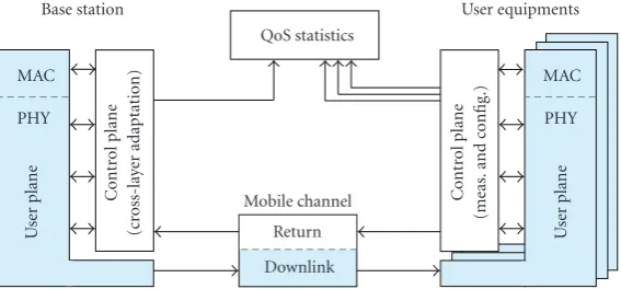
Figure1: Simplified Simulator Architecture.
simulator architecture allows having a fully configurable MIMO-OFDM transmission, including the main next gen-eration MIMO-OFDM schemes. The simulator has been used to evaluate the performance of the LTE technology according to the parameters configuration defined by the 3GPP standard [1]. The different MIMO-OFDM techniques included in LTE are evaluated under realistic assumptions such as user mobility, antenna correlation, or bandwidth-limited feedback channel.
The rest of this paper is structured as follows. First, a description of the simulator architecture and functionalities is provided in Section 2. Next, Section 3 presents several simulation results for different LTE scenarios and MIMO-OFDM configurations. Finally, the main conclusions are summarized inSection 4.
2. Simulator Architecture
The simulator is composed by a number of User Equipments (UEs) connected to a Base Station (BS) through a frequency-selective Rayleigh fading channel. The corresponding high-level architecture is depicted inFigure 1.
BS and UEs functionalities are split into user and control planes. In general, the control plane includes most of the BS/UE intelligence, acting as a decision point to configure user plane functionalities. In the case of the UEs, control plane is also responsible for performing physical layer measurements and for periodically reporting quality-related information to the BS through a return channel; such information is used by the BS to perform a cross-layer link adaptation, as described in next subsections. The user plane includes a group of functionalities (configured from the control plane) to facilitate the actual data transmission.
The simulator also includes a module responsible for collecting Quality of Service (QoS) statistics. A detailed description of the whole architecture is given in next subsections.
2.1. Base Station. The BS is responsible for scheduling
the transmission turns to different UEs, for maintaining a reliable radio link between each UE and the BS (by dynamically adapting the transmission parameters) as well
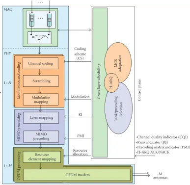
as for transmitting data packets to the UEs. A detailed block diagram of the BS architecture (downlink) is depicted in
Figure 2.
Incoming data packets arrive at the MAC layer following a “full-buffer” model; that are, data is always available at the transmission queues. Thus, typical performance indicators like spectral efficiency or Bit Error Rate (BER) are not service-dependent. User data at the MAC layer are extracted from the queues according to the decisions taken in the cross-layer (PHY-MAC) scheduling, as explained later.
Physical layer functionalities are grouped into three subsystems.
(i)Modulation and Coding: this subsystem is responsible for channel coding, scrambling, and modulation mapping of each transport block. The required number of instances of this subsystem is N, being
N the number of code words. Throughout this paper, the termcode wordwill be employed to refer an independently coded and modulated transport block. These functions are managed from the control plane, where the Modulation and Coding Scheme (MCS) adaptation is performed and the Hybrid Automatic Repeat reQuest (H-ARQ) block processes the requested retransmissions of corrupted code words.
(ii)MIMO Processing: the use of MIMO technology
requires additional processing in order to adequate the data streams to be transmitted over the multi-ple antennas. Hence, this subsystem is responsible for mapping and precoding the modulation sym-bols according to a particular configuration, which depends on the MIMO transmission mode (e.g., transmit diversity, beamforming, or spatial multi-plexing). This processing is strongly related to the rank/precoding selection carried out at the control plane (as described later).
M
-Channel quality indicator (CQI) -Rank indicator (RI)
-Precoding matrix indicator (PMI) -H-ARQ ACK/NACK
· · ·
Figure2: Base Station Architecture (downlink).
2.1.1. Cross-Layer Scheduling. The time variability of wireless channels leads to rapid changes in the short-term channel capacity over time. In an OFDM-based technology, the channel response associated to each OFDM subcarrier also varies along the frequency domain. Consequently, chan-nel response can be seen as a time-frequency random process. In a multiuser environment, channel quality also varies independently for different users. Such variations in time-frequency channel conditions for each user can be exploited by a cross-layer scheduler to increase system throughput.
Figure 3 shows an example of how the instantaneous Channel State Information (CSI) is used to perform cross-layer scheduling. Upper 3D graph depicts the instantaneous Signal-to-Noise Ratio (SNR) received by two users. SNR values are periodically reported to the BS via Channel Quality Indicators (CQIs), which are used by the scheduler to decide the time-frequency resource allocation for each UE (depicted in the lower graph).
When OFDM is jointly used with multiple antennas, a fourth dimension is added to the scenario. Hence, the
multiplexing algorithm has a high degree of flexibility as it works on a time-frequency-space-user basis.
The time-variant radio channel and user specific condi-tions (e.g., speed) imply the need for adapting or switch-ing the MIMO configuration to be applied to each user. The adaptation of the MIMO scheme is accomplished by the cross-layer scheduler, which selects dynamically the appropriate scheme for each user. The scheduler decisions are based on the per-user reported PHY measurements as CQI, Rank Indicator (RI), and Precoding Matrix Indicator (PMI). Other considerations such as the terminal speed or Quality of Service (QoS) requirements (e.g., priority handling) can be also taken into account in the scheduling process.
Instantaneous
Figure3: Example of cross-layer scheduling for two users [2].
configuration to be applied, and the PHY resources for data transmission.
2.1.2. Modulation and Coding. Adaptive Modulation and
Coding (AMC) techniques [2] are used to improve data throughput whereas BER is kept below a predefined target value (BERT). Modulation and coding schemes are jointly
changed by the BS to adapt the transmitted signal to the varying channel conditions both in time and, in frequency domains.
The control plane is responsible for making decisions on MCS adaptation, whereas the user plane enforces such decisions. MCS adaptation is based on the instantaneous CQI reported from the terminals. For the sake of simplicity, only the processing chain for transport channels is described below as the equivalent one for control channel is usually similar except for the channel coding scheme applied.
User plane processing includes the following functional-ities:
(i)Channel Coding: the channel coding procedure is
based on LTE specifications [6]. In the first place, a Cyclic Redundancy Check (CRC) is appended to each transport block coming from the MAC layer. The resulting bit sequence is segmented, if needed, and an additional CRC is added to each resulting segment. Then, a turbo coding with mother coding rate 1/3 is applied to each segment for transport channels. On the other hand, a tail biting convolutional coding with mother rate 1/3 is applied to control channels. Finally, a rate matching process is applied to each coded segment to match the final coding rate indicated by the MCS information. Rate-matched coded sequences are concatenated to form a code word.
(ii)Scrambling: the purpose of this block is to ensure that the receiver-side decoding can fully utilize
the processing gain provided by the channel coding. Scrambling operation consists of an exclusive-or operation between the code word and a bit-level scrambling sequence.
(iii)Modulation Mapping: scrambled code words are mapped onto the modulation scheme selected from the control plane, thus generating a sequence of complex modulated symbols.
Hybrid-ARQ (Automatic Repeat-reQuest) has become an essential physical layer feature in mobile communication systems like WiMAX or LTE [7,8]. H-ARQ allows retrans-missions of a packet at the MAC/PHY level, with significant advantages like delay reduction and/or increased capacity. H-ARQ may be jointly used with Chase Combining (CC)
andIncremental Redundancy(IR) features [9]. WhenChase
Combiningis applied, an erroneous code word is stored at the receiver in order to be combined with other retransmitted code words.Incremental Redundancyis based on the trans-mission of a punctured version of the original code word. If the decoding fails, additional redundancy information is transmitted thus having a different puncturing scheme and hence, facilitating the decoding. The process may be repeated until either a successful decoding or a maximum number of retransmissions is reached. H-ARQ procedures are tightly integrated with the cross-layer scheduler, which takes into account pending retransmissions (from ACK/NACK reports) and associated redundancy versions.
2.1.3. Transmit MIMO Processing. The MIMO-OFDM
trans-mission schemes currently being incorporated to next gener-ation wireless standards have been included in the simulator in order to provide a fully configurable MIMO-OFDM transmission. The transmit MIMO processing framework may be configured by the control plane in order to apply different MIMO schemes, including both transmit diversity and spatial multiplexing.
(I)Transmit Diversity: it is used to overcome the effects of fading by transmitting redundant information from different antennas. In particular, the following schemes are supported:
(i) space-frequency block codes (SFBC), (ii) transmit beamforming (BF).
(II)Spatial Multiplexing: it is used to increase the spectral efficiency by transmitting simultaneously several data streams from the multiple transmit antennas. The following schemes are supported:
(i) open-loop spatial multiplexing (MUX without precoding),
(ii) precoded spatial multiplexing (Precoded MUX).
···
(a) Precoded SM with 2 codewords, 3 layers, and 4 antennas
(b) Transmit Beamforming with 4 antennas
Figure4: Transmit MIMO processing with different configurations for (a) precoded spatial multiplexing and (b) Transmit beamforming.
C -Channel quality indicator (CQI) -Rank indicator (RI)
-Precoding matrix indicator (PMI) -H-ARQ ACK/NACK
Frequency
Figure 6: Example of 2D pilot arrangement with 2-antenna transmission.
port. As shown in Figure 2, the complete transmit MIMO processingis separated into two functionalities,layer mapping
andMIMO precoding, which are defined in a different way
depending on the MIMO scheme to be applied.
(1)Layer Mapping: its purpose is to map the modulation symbols of different code words (independently coded transport blocks) onto the spatially multi-plexed streams (layers) that will be transmitted. The number of code words must be less than or equal to the number of layers, which is indicated by the RI. Symbols from the same code word can be mapped to one or several layers, as shown in Figure 4. The number of layers may be dynamically adapted to the rank of the channel matrix in spatial multiplexing schemes, thus making possible to performrank adap-tation. The cross-layer scheduler selects the number of layers of the transmission, which is forwarded to the layer mapping functionality by means of the RI. Although the concept of layer does not apply to transmit diversity schemes, the same mapping is assumed with some distinctions: BF is considered as a special case of spatial multiplexing with one-layer transmission, whereas in SFBC the number of layers is always equal to the number of antennas.
(2)MIMO Precoding: one modulation symbol is
extracted from each layer, being the resulting vector processed according to the applied MIMO scheme. In case of closed-loop schemes (i.e., BF and precoded SM) the precoding matrix indicated by PMI is applied. In the open-loop SM scheme, the PMI is set to the identity matrix (i.e., no precoding is applied). If SFBC is selected (with a reserved value in PMI), the coding and mapping procedure defined by SFBC [10] is performed consequently. The output of MIMO precoding is an M-size vector of complex values to be mapped onto the M antennas.
An example of MIMO processing is depicted inFigure 4with two different configurations for three-layer spatial multiplex-ing and beamformmultiplex-ing. The particular configuration of spatial multiplexing depicted inFigure 4(a)corresponds to 2 code words that are transmitted over 3 spatially multiplexed layers and 4 transmit antennas. The precoding stage performs the conversion from 3 layers to the 4 antennas of the base station by means of the precoding matrix, which is selected from the corresponding indexed position (PMI) within a codebook. On the other hand, Figure 4(b)shows the transmit beamforming configuration corresponding to 4 transmit antennas. In this case, only one code word and one layer are allowed since no spatial multiplexing will be performed (i.e., the layer mapping functionality is transparent). Therefore, the precoding matrix becomes a precoding vector, also called beamformer, which is also determined by the corresponding PMI value.
The configurable MIMO processing framework allows for selecting dynamically the MIMO scheme to be applied to different physical channels. A MIMO scheme is completely determined (including precoding details if necessary) by the pair of values {RI, PMI}. Thus, the complete MIMO processing is configured by the control plane with proper RI and PMI values for each of the physical channels being processed.
The adaptation of the MIMO scheme is accomplished by the cross-layer scheduler, which selects dynamically the appropriate scheme for each user. Once the scheduling functionality has made the decision, the different physical data channels are processed by the MIMO framework. As detailed above, this framework allows for changing the settings of a certain MIMO configuration (e.g., number of layers or precoding matrix), as well as switching to a different MIMO scheme by simply updating the RI and PMI values.
2.1.4. Transmit OFDM Processing. The generation of the
OFDM signal to be transmitted towards the radio interface requires the following processing blocks.
(i)Resource Element Mapping: resource allocation infor-mation from the control plane is used to map modulation symbols to specific resource elements in the time-frequency resource grid for each antenna.
(ii)OFDM Transmission Modem: once a subframe is
completed, OFDM symbols must be sent orderly to the receiver. In the first place, OFDM symbols are converted into the time domain by means of an M-point Inverse Fast Fourier Transform (M-IFFT). Afterwards, a cyclic prefix (CP) is added to each OFDM symbol. Finally, the power of the transmitted signal is normalized.
0
512 carriers 1024 carriers 2048 carriers
WM-SIM VSS
Simulink Ptolemy II
Figure 7: Execution time consumption for different simulation platforms.
Control plane in the UE plays two roles.
(i)Physical Layer Measurements and Reporting: a set of indicators are periodically reported to the BS so that link adaptation can be applied at the transmitter side. In particular, the UE shall estimate the Signal to Interference-plus-Noise Ratio (SINR), suggest the BS to use a certain rank (RI) and precoding matrix (PMI) for a given transmit MIMO configuration, and request potential retransmissions via H-ARQ ACK/NACK messages.
(ii)Physical Layer Configuration: control channels (CCH) sent from the BS carry essential control informa-tion for user plane configurainforma-tion. Therefore, CCH decoding (whose details are omitted for the sake of simplicity) is the first task to be fulfilled before processing user data. Concretely, control channels include scheduling assignments (i.e., resource allo-cation, modulation and coding scheme) as well as MIMO-related information like the RI and PMI applied by the BS. All this control information is used to configure the different user plane functions, as depicted inFigure 5.
User plane subsystems are analogous to the ones listed for the base station, although specific processing is required at the receiver side.
(i)OFDM Processing: received time-domain symbols
through each of the M antennas must be syn-chronized and processed to form a complete time-frequency resource grid.
(ii)MIMO Processing: this subsystem is in charge of
detecting the different data streams (or layers) that have been transmitted from the BS. This task requires certain information from the control plane, like the estimated CSI and the RI/PMI used by the BS (decoded from control channels). In MIMO-OFDM systems, CSI is essential at the receiver in
order to coherently detect the received signal and to perform diversity combining or spatial interference suppression.
(iii)Demodulation and Decoding: this subsystem is responsible for the channel decoding, descrambling and modulation demapping of each of the N data streams. The configuration of these functions is per-formed from the MCS, which is previously decoded from control channels.
2.2.1. Receive OFDM Processing. Each UE must process
OFDM signals from the different receive antennas. This pro-cessing is differentiated between control plane and user plane functionalities. Processing at the user plane is performed by the two following blocks.
(i)OFDM Modem: this block is dual to the OFDM
transmission modem at the BS; that is, cyclic prefix is removed from the received OFDM symbol in the time domain; then, an N-FFT is applied to convert OFDM symbols into the frequency domain. It also recovers the reference pilots required by the channel estimation block.
(ii)Resource Element Demapping: once all the OFDM
symbols corresponding to a subframe are received, the complete subframe is processed in a dual manner as done at the transmitter side. That is, information from the control plane is used to extract the mod-ulated symbols from their corresponding resource elements.
At the control plane, several estimates and measurements are derived upon reception of the OFDM signal. Specifically, the following functionalities are included.
(i)Channel Estimation: Channel estimation is based on pilot symbol arrangement within the 2D OFDM resource grid, where pilots are spread along both time and frequency domains (seeFigure 6). With this pilot arrangement, an efficient channel estimation method may apply a 2D time-frequency interpolation in order to estimate the channel frequency response at all subcarriers within the complete subframe time interval (i.e., for the entire OFDM resource grid). Channel estimate (H) is employed with different purposes both in user and control planes at the receiver. On the one hand, the channel estimate is provided to the MIMO detection block in the user plane to recover the transmitted complex symbols from the received signals. On the other hand, the channel estimate is used to derive several channel measurements that will be reported back to the base station for link adaptation purposes. These measurements include the channel quality, rank, and precoding indicators (namely CQI, RI, and PMI). (ii)SINR Estimation: effective (or postdetected) SINR
Frequency
Ti
m
e
1200 data subcarriers (20 MHz) 12
Subcarriers
· · ·
· · ·
··· ···
TT
I
(14
O
FDM
sy
m
bols)
Slot
#1
Slot
#2
PRB #1
PRB #1
PRB #2
PRB #2
PRB#100
PRB#100
Pilot symbol
Not used (reserved for pilots from other antennas)
Minimum allocable unit
Figure8: LTE physical resources structure.
10−5 10−4 10−3 10−2 10−1 100
BER
0 5 10 15 20 25 30
SNR (dB) MUX w/o precoding Precoded MUX
SFBC BF
Figure9: Average BER for different MIMO-OFDM techniques with a fixed spectral efficiency of 4 bits/s/Hz and low spatial correlation (v=3 km/h,ρ=0.3).
applied and it is derived from the channel estimate
H. Note that the MIMO link can be seen as an equivalent end-to-end SISO channel with an effective SNR which depends on the applied MIMO scheme. The effective SINR is then converted into a quantized CQI value for reporting the channel quality back to the base station through the uplink control channels. In case of spatial multiplexing, a different CQI value is derived for each layer of the transmission.
(iii)Rank/Precoding Estimation: the suitable rank and preferred precoding matrix are derived from the channel estimateH for each frequency subband, so that RI and PMI values can be reported back to the base station for adapting the MIMO transmission.
2.2.2. Receive MIMO Processing. The receive MIMO
process-ing block is in charge of recoverprocess-ing the complex modula-tion symbols that were transmitted through the multiple antennas. The per-antenna received complex symbols are taken as inputs to provide, as a result, a detected version of the complex modulation symbols that were transmitted for each code word. Following a similar approach to that of the transmitter, the receive MIMO processing is separated into two functionalities: MIMO detection andlayer demapping. These functionalities are defined according to the MIMO scheme applied at the transmitter, provided that several schemes are supported in the simulator (seeSection 2.1.3).
10−5 10−4 10−3 10−2
BER
0 5 10 15 20 25 30 35
SNR (dB) BF
MUX w/o precoding
Precoded MUX SFBC BERT
ASE
(bits/s/Hz)
0 5 10 15 20 25 30 35
SNR (dB) BF
MUX w/o precoding
Precoded MUX SFBC 0
2 4 6 8 10 12
Figure10: Average BER and ASE with adaptive modulation and BERT=10−3(v=3 km/h,ρ=0.3).
(i)MIMO Detection: the objective of the detection
process is to provide the complex modulation sym-bols that were transmitted onto the different layers. Different detection strategies are implemented since the detection problem is associated to the MIMO technique applied at the transmitter. Linear detection and low-complexity algorithms based on successive interference cancellation [11] are supported by the simulator. In case of SFBC transmission, the linear processing defined in [10] is carried out in order to obtain the transmitted complex modulation sym-bols. When precoding-based schemes are applied, the effective channel matrix is needed in order to perform the detection. The effective channelHeff =
H∗Vis derived from the channel estimateHand the precoding matrixVindicated by PMI.
(ii)Layer Demapping: it performs exactly the inverse
function of the layer mapping, described in
Section 2.1.3. In this case, the complex symbols transmitted over the different layers of the transmission are de-mapped into the corresponding code words to be subsequently decoded (as described in the next section).
2.2.3. Demodulation and Decoding. At the receiver side,
incoming modulated symbols are converted to bit sequences and processed in order to recover the original transport blocks. The UE is aware of the instantaneous MCS applied to the data from the signalling information contained in the corresponding control channels. The following processing blocks are included.
(i)Modulation Demapping: the sequence of received
complex symbols is demapped according to the MCS information provided by the control plane.
(ii)Descrambling: the scrambling process carried out at the receiver is undone to recover the descrambled code word.
(iii)Channel Decoding: the received code word has to be processed to reverse the rate-matching process before being decoded. Once the decoding is complete, the transport block CRC integrity is checked. If segmentation took place at the transmitter, the CRC of each individual segment is checked before.
If data integrity is preserved, an ACK message is sent to the transmitter through uplink control channels. Otherwise, a NACK message is sent to request a retransmission. If CC and/or IR features are applied, the erroneous code word is stored at the receiver to be combined (CC) or added (IR) to forthcoming code words, as described in
Section 2.1.2.
2.3. Mobile Channel. The mobile channel subsystem allows
simulating a MIMO transmission through the radio link. The effects of antenna spatial correlation and frequency-selective Rayleigh fading are included. Specifically, the standard spatially correlated Rayleigh-faded multiantenna channel model [12] is considered. Channel gain is modeled by a 2×2 complex matrixH, so that the entriesH =(hi j) denote the
channel gain between the jth transmit and theith receive antenna. The multitap channel delay profile is fully con-figurable. Assuming the well-known Kronecker correlation structure [12], the channel matrix can be decomposed as
H=R1/2
rx ·G·R1tx/2, where the entries ofGare independent
5 10 15 20 25 30 35 40
Figure11: Mean transmission delay for different MIMO schemes when using adaptive modulation subject to restriction BERT=10−3in a
pedestrian channel (v=3 km/h,ρ=0.3) with different average SNRs.
antennas, thus being the correlation matrices Rtx and Rrx
identical and given by
Rtx=Rrx=
The effect of Additive White Gaussian Noise (AWGN) at the receive antennas is also included. Assuming the frequency domain baseband model, the received signal vector can be expressed as y = H ·x +n, where x is the transmitted signal vector andnis the channel noise vector, whose entries are i.i.d. Gaussian RVs with zero mean and varianceσ2
n. As
the transmitted signal is power normalized, the average SNR determines the average noise power. Thus, we define the average SNRγin terms of the transmit power constraint and the noise power asγ=1/σ2
n[13].
The simulator includes the ability to run over a time domain channel model (with higher accuracy) or over an equivalent frequency domain channel model (to minimize computational costs). If the later is selected, OFDM modems are disabled, being OFDM symbols merely affected by chan-nel frequency response. However, it should be noted that performance results over an equivalent frequency domain channel are only valid under the premise that transmission is free of Intersymbol Interference (ISI) and Intercarrier Interference (ICI).
2.4. QoS Statistics. A QoS statistics block allows assessing the impact of PHY layer impairments on upper layers’ QoS by collecting performance statistics from both sides of the communication (as shown in Figure 1). This block is aware of the status of the BS and all UEs in the simulation scenario (queue occupancy at BS, transmitted/received bits
sequences, etc.). This global knowledge allows obtaining QoS indicators like BER, BLock Error Rate (BLER), transmission delay, throughput, as well as occupancy and loss rate in the transmission queues.
3. Simulation Results
The presented simulator allows for evaluating the main physical and MAC layer functionalities of a MIMO-OFDMA-based system. The performance of different adaptive trans-mission techniques and MIMO schemes may be evaluated in a complete downlink system that takes into account most of the impairments of a realistic scenario.
As aforementioned, the proposed simulator is proved to outperform Simulink, VSS and Ptolemy II.Figure 7shows a performance comparison among these platforms for a simplified OFDM scenario (see [4] for further details).
This simulator has been used to support several research works in the context of adaptive OFDMA, and MIMO based systems. In [11], different low-complexity MIMO detection algorithms are evaluated in a realistic LTE downlink scenario and a performance-complexity tradeoff is established. An adaptive MIMO transmission is proposed in [14] for an OFDMA-based cellular system under practical limitations such as imperfect CSI at the transmitter due to user mobility. Along this section, simulation results are shown for a typical configuration of the 3GPP LTE technology [1], which is summarized in the next subsection.
3.1. LTE Configuration. LTE radio resources are structured
in slots of lengthTslot = 0.5 millisecond. The Transmission
10−5 10−4 10−3 10−2
BER
0 5 10 15 20 25 30 35
SNR (dB) BF (10 kmh)
BF (20 kmh) BF (30 kmh)
BF (40 kmh) BF (60 kmh) BF (80 kmh) BERT
10−5 10−4 10−3 10−2
BER
0 5 10 15 20 25 30
SNR (dB) SFBC (60 kmh)
SFBC (70 kmh) SFBC (80 kmh)
Precoded MUX (10 kmh) Precoded MUX (20 kmh) Precoded MUX (30 kmh)
BERT
Figure12: Evaluation of the maximum admissible user speed for different MIMO schemes under adaptive modulation.
10−5 10−4 10−3 10−2
BER
0 5 10 15 20 25 30 35
SNR (dB) BF-ideal
Precoded MUX-ideal
BF-codebook
Precoded MUX-codebook BERT
(a)
ASE
(bits/s/Hz)
0 5 10 15 20 25 30 35
SNR (dB) BF-ideal
Precoded MUX-ideal
BF-codebook
Precoded MUX-codebook 0
2 4 6 8 10 12
(b)
Figure13: Performance degradation due to codebook based precoding.
slots. Each slot can be seen as a time-frequency resource grid composed by several OFDM symbols. Each slot is divided into a number of Physical Resource Blocks (PRBs), each of them consisting of 12 consecutive subcarriers along 7 consecutive OFDM symbols. Assuming a system bandwidth BW = 20 MHz, a total of 1200 data subcarriers (i.e., 100 PRBs) is available for transmission. The minimum allocable unit to a user is formed by two consecutive PRBs along the time. Although LTE specifications state that the first OFDM symbols (from 1 to 3) in a TTI are reserved for control channels (signaling), our simulations only assume reference signals overhead, as shown inFigure 8.
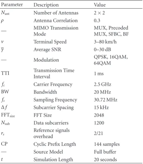
A typical value of antenna correlationρ =0.3 has been considered from previous works on the antenna correlation for a typical suburban scenario and linear antenna arrays [15]. A 9-tap typical urban channel delay profile has been considered [16]. The rest of simulation parameters is summarized inTable 1.
50
Figure14: Multiuser diversity gain with Proportional Fair schedul-ing (average SNR 20 dB).
Table1: Simulation parameter values.
Parameter Description Value
Nant Number of Antennas 2×2
ρ Antenna Correlation 0.3
— MIMO Transmission
Mode
MUX, Precoded MUX, SFBC, BF
v Terminal Speed 3–80 km/h
γ Average SNR 0–30 dB
— Modulation QPSK, 16QAM,
64QAM
TTI Transmission Time
Interval 1 ms
fc Carrier Frequency 2.5 GHz
BW Bandwidth 20 MHz
fs Sampling Frequency 30.72 MHz Δf Subcarrier Spacing 15 kHz
FFTsize FFT Size 2048
Nsub Data subcarriers 1200
rs Reference signals
overhead 2/21
CP Cyclic Prefix Length 144 samples
— Source Model Full buffer
t Simulation Length 20 seconds
in terms of average BER, average spectral efficiency (ASE), and mean transmission delay.
The presented results are organized as follows. First, the average BER is evaluated without any adaptive modulation mechanism, that is, under a fixed given spectral efficiency. Afterwards, the performance analysis is focused on the adaptive modulation mechanism and, thus, the average BER, spectral efficiency, and mean transmission delay are provided
for the different MIMO-OFDM schemes. Next, different impairments associated to a realistic scenario are tackled. Specifically, the maximum admissible user speed under a given target BER (BERT) requirement is evaluated for the
different MIMO techniques. Finally, the performance degra-dation due to nonideal (i.e., codebook based) precoding is addressed.
Figure 9shows the average BER results associated to the four MIMO-OFDM techniques. In order to provide a fair comparative analysis, a fixed spectral efficiency of 4 bits/s/Hz is achieved by employing different modulation order for the different MIMO techniques; that is, QPSK is employed for spatial multiplexing schemes whereas 16-QAM is used in case of transmit diversity (i.e., SFBC and BF schemes). Simulation results show that the transmit diversity schemes outperform (for the entire range of SNR) the multiplexing ones in terms of BER. Besides, precoding allows reducing significantly the interference among transmitted signals at the receiver and, therefore, it improves the performance when applied to the MUX technique.
Figures10and11show different performance metrics of the different MIMO-OFDM schemes with adaptive modula-tion. An instantaneous BER restriction is assumed for all the simulations so that BER is maintained below a predefined target (BERT = 10−3). Possible modulation schemes are
QPSK, 16-QAM, and 64-QAM, as well as no transmission (outage). An error-free feedback channel is assumed and ideal precoding based on singular value decomposition (SVD) of the channel matrix is employed for the BF and precoded MUX techniques.
InFigure 10, the average BER and corresponding ASE is depicted as a function of the average SNR for the different MIMO-OFDM schemes. It can be seen that the average BER remains under the BERT within the entire SNR range for
all the schemes. Regarding the ASE, different results for the low and high SNR regime are obtained (seeFigure 10). In the low SNR regime, BF provides the highest ASE compared to other schemes; however, the achieved ASE for transmit diversity techniques (both BF and SFBC) reaches a satura-tion level (6 bits/s/Hz) as the average SNR increases. This saturation level corresponds to the maximum achievable ASE by transmitting only one data stream with the maximum modulation order (64-QAM). On the other hand, the spatial multiplexing techniques provide the highest ASE (close to 12 bits/s/Hz) in the high SNR regime due to the simultaneous transmission of two data streams. Moreover, a significant ASE improvement is shown for the MUX technique when precoding is applied (ASE increases 2 bits/s/Hz when average SNR is 20 dB).
limit for the admissible load with BF is about 30–35 Mbps, significantly higher than the one achieved with the other schemes. In case of high SNR regime (Figure 11(b)), it is shown that MUX schemes (specially the precoded MUX) clearly outperform the transmit diversity schemes.
Figure 12shows how average BER is degraded as user speed increases due to the outdated CQI and PMI reports. It is observed that the maximum user speed that fulfills the BER requirement for BF is around 60–70 km/h, which is significantly higher that the one for precoded MUX scheme (about 20 km/h). However, SFBC is shown to be the most robust technique in high mobility scenarios as the maximum admissible user speed is around 80–90 km/h. This is due to the fact that, unlike the BF scheme, SFBC is not affected by the outdated PMI reports.
Another impairment associated to a realistic sce-nario is the bandwidth limited feedback channel, which makes unfeasible to report the exact (ideal) precoding matrix to the base station. Therefore, codebook-based precoding is employed and only an index which indi-cates a predefined precoding matrix (within the code-book) is reported. Figure 13 shows the performance degradation in terms of average BER (a) and ASE (b) when a codebook-based precoding is applied instead of ideal (SVD based) precoding. The two-bit codebook defined in LTE [17] is assumed for the simulations. It is observed that the performance degradation (both in average BER and ASE) associated to BF is negligible, while the precoded MUX performance is degraded signifi-cantly.
As described in Section 2.1.1, the scheduling policy applied at the MAC layer plays an important role in the overall system performance. Figure 14 shows the total cell throughput for a different number of users in the cell when applying a Proportional Fair (PF) scheduling policy. Simulation results show the multiuser diversity gain achieved by PF for different MIMO schemes, which can be seen as an effective SNR gain in the radio link. For SFBC and BF, the maximum achievable cell throughput is
Rcell ≈ 91.5 Mbps, which corresponds to the maximum
ASE of 6 bits/s/Hz shown inFigure 10, taking into account the physical resources structure defined in Table 1, that is,
Rcell ≈ ASE·Nsub·(1−rs)· fs/(CP + FFTsize). Although
MUX without precoding is the worst scheme for a single user in the cell, both MUX-based schemes achieve the highest multiuser diversity gain as the transmission of two simultaneous streams provides a higher degree of freedom. Anyhow, precoded MUX outperforms the previous scheme both in throughput and BER due to the reduction of the cochannel interference achieved by means of precoding.
4. Conclusions
In this paper, we present a simulator for next genera-tion MIMO-OFDM-based wireless systems. The simulator includes the main functionalities carried out at the physical and MAC layers of a wireless MIMO-OFDM system. Further on, a detailed description of the simulator architecture and main functionalities is provided. With this architecture, it is
shown that a fully configurable MIMO-OFDM transmission is supported, including all the MIMO-OFDM schemes being incorporated to next generation wireless standards.
This simulator has been used to evaluate the perfor-mance of the 3GPP LTE technology, whose simulation results are here presented and analyzed. Performance results are provided for the different MIMO-OFDM techniques included in LTE under realistic assumptions such as user mobility or bandwidth limited feedback channel. It has been proved that spatial multiplexing techniques provide the best spectral efficiency for high SNR although very low terminal speeds (up to 20 km/h) are supported to fulfill the reliability requirements. On the other hand, SFBC is shown to be the most robust technique in high mobility scenarios as the maximum admissible user speed is around 80–90 km/h.
Acknowledgments
This work has been partially supported by the Spanish Gov-ernment (projects TIC2003-07819 and TEC2007-67289), Junta de Andaluc´ıa (Proyecto de Excelencia TIC 03226), and AT4wireless.
References
[1] 3GPP TS 36.201, “Long Term Evolution (LTE) physical layer; General description,” Release 8, V8.3.0, March 2009.
[2] G. G ´omez, D. Morales-Jim´enez, F. J. L ´opez-Martinez, J. J. S´anchez, and J. T. Entrambasaguas, “Radio-interface physical layer,” inLong Term Evolution: 3GPP LTE Radio and Cellular
Technology, chapter 3, pp. 49–98, Auerbach, Boca Rat ´on, Fla,
USA, April 2009.
[3] C. Mehlfuhrer, M. Wrulich, J. C. Ikuno, D. Bosanska, and M. Rupp, “Simulating the long term evolution physical layer,”
inProceedings of 17th European Signal Processing Conference
(EUSIPCO ’09), pp. 1471–1478, Glasgow, Scotland, August
2009.
[4] J. J. S´anchez, D. Morales-Jim´enez, G. G ´omez, E. Martos-Naya, U. Fern´andez-Plazaola, and J. T. Entrambasaguas, “WM-SIM: a platform for design and simulation of wireless mobile systems,” inProceedings of the 2nd ACM Workshop on Performance Monitoring and Measurement of Heterogeneous
Wireless and Wired Networks (PM2HW2N ’07), pp. 124–127,
Chania, Greece, October 2007.
[5] D. Mart´ın-Sacrist´an, J. F. Monserrat, J. Cabrejas-Pe˜nuelas, D. Calabuig, S. Garrigas, and N. Cardona, “On the way towards fourth-generation mobile: 3GPP LTE and LTE-advanced,”EURASIP Journal on Wireless Communications and
Networking, vol. 2009, Article ID 354089, 10 pages, 2009.
[6] J. Lee, J.-K. Han, and J. Zhang, “MIMO technologies in 3GPP LTE and LTE-advanced,”EURASIP Journal on Wireless
Communications and Networking, vol. 2009, Article ID 302092,
10 pages, 2009.
[7] J. J. S´anchez, D. Morales-Jim´enez, G. G ´omez, and J. T. Enbrambasaguas, “Physical layer performance of long term evolution cellular technology,” inProceedings of the 16th IST
Mobile and Wireless Communications Summit, July 2007.
[8] M. Ergen, Mobile Broadband Including WiMAX and LTE, Springer Science+Business Media LLC, 2009.
redundancy for HSDPA,” in Proceedings of the 54th IEEE
Vehicular Technology Conference (VTC ’01), vol. 3, pp. 1829–
1833, Atlantic City, NJ, USA, October 2001.
[10] M. J. Dehghani, R. Aravind, S. Jam, and K. M. M. Prabhu, “Space-frequency block coding in OFDM systems,” in Pro-ceedings of IEEE Region 10 Conference: Analog and Digital
Techniques in Electrical Engineering (TENCON ’04), pp. A543–
A546, Chiang Mai, Taiwan, November 2004.
[11] D. Morales-Jim´enez, J. F. Paris, and J. T. Entrambasaguas, “Performance tradeoffs among low-complexity detection algorithms for MIMO-LTE receivers,”International Journal of
Communication Systems, vol. 22, no. 7, pp. 885–897, 2009.
[12] D.-S. Shiu, G.J. Foschini, M.J. Gans, and J. M. Kahn, “Fading correlation and its effect on the capacity of multielement antenna systems,”IEEE Transactions on Communications, vol. 48, no. 3, pp. 502–513, 2000.
[13] A. Goldsmith,Wireless Communications, Cambridge Univer-sity Press, New York, NY, USA, 2005.
[14] D. Morales-Jim´enez, G. G ´omez, J. F. Paris, and J. T. Entram-basaguas, “Joint adaptive modulation and MIMO transmis-sion for non-ideal OFDMA cellular systems,” inProceedings of the 5th IEEE Broadband Wireless Access Workshop Colocated
with IEEE GLOBECOM, Honolulu, Hawaii, USA, December
2009.
[15] K. I. Pedersen, J. Andersen, J. Kermoal, and P. Mogensen, “A stochastic multiple-input-multiple-output radio channel model for evaluation of space-time coding algorithms,” in
Proceedings of the 52nd IEEE Vehicular Technology Conference
(VTC ’00), vol. 2, pp. 893–897, Boston, Mass, USA, September
2000.
[16] 3GPP TS 36.521-1, “User Equipment (UE) conformance specification Radio transmission and reception, Part 1: Con-formance Testing,” Release 8, V8.1.0, March 2009.
![Real time processing on the road: a guided tour of [iks]'s abstr/cncr setup](data:image/gif;base64,R0lGODlhAQABAIAAAP///wAAACH5BAEAAAAALAAAAAABAAEAAAICRAEAOw==)