R E S E A R C H
Open Access
A low-complexity peak cancellation scheme
and its FPGA implementation for
peak-to-average power ratio reduction
Jiajia Song
*and Hideki Ochiai
Abstract
The power amplifier (PA) is the most power-hungry component in a wireless base station transmitter, and reducing the peak-to-average power ratio (PAPR) of wireless signals is an important issue for its effective use. In this paper, we focus on a field-programmable gate array (FPGA) implementation of the peak cancellation (PC) technique, which is known as the simplest method for PAPR reduction. The design issue of effective peak-cancelling pulses under the constraint on the out-of-band emission is addressed. In order to reduce its hardware complexity, a novel approach for generating peak-cancelling pulses is also presented. The experimental results based on long-term evolution
(LTE)/LTE-Advanced and multi-band Wideband Code Division Multiple Access (WCDMA) signals demonstrate the validity of the proposed scheme. It has been shown that the proposed PC scheme can achieve lower in-band distortion than the conventional PC with an acceptable loss in out-of-band performance. Our study also includes mapping the signal processing methods onto a Xilinx virtex-7 FPGA device running at 245.76 MHz and addresses the resource utilization and the hardware design in detail.
Keywords: PAPR reduction; Peak cancellation; FPGA; OFDM; LTE; LTE-Advanced; Multi-band; WCDMA
1 Introduction
Signals such as orthogonal frequency division multiplex-ing (OFDM) [1] and direct-sequence spread spectrum (DS-SS) for code division multiple access (CDMA) [2] are widely adopted in modern wireless communication systems due to their remarkable advantages such as flexi-ble allocation of resources and high-spectrum utilization. As these signals are essentially a sum of multiple sub-carriers/codes of multiple users in either frequency or time domain, the probability density functions (PDFs) of their signals tend to approach Gaussian, and thus, they exhibit high peak-to-average power ratio (PAPR) [3]. This poses strict demands on the dynamic range of data converters and especially limits efficient opera-tion of the power amplifiers (PAs). Reducing the PAPR is hence important for boosting the PA efficiency by allowing higher average input power before saturation
*Correspondence: [email protected]
Department of Electrical and Computer Engineering, Yokohama National University, 79-5 Tokiwadai, Hodogaya, Yokohama 240-8501, Japan
occurs. To mitigate this issue, extensive studies have been performed [4-6].
Some of the PAPR-reduction techniques for Wideband Code Division Multiple Access (WCDMA) system can be found in, for example, [7,8]. On the other hand, those for multi-carrier and OFDM signals are much more abundant and appear in many forms including selected mapping (SLM) [9] and partial transmit sequence (PTS) [10,11], just to mention a few. The aforemen-tioned techniques do not incur distortion, but they either have a large computational complexity or have to modify the signal, which makes their implementa-tion in high-speed real-time systems challenging or hin-ders standard-compliant operations. It should be noted that, as the digital techniques in a transmitter continue to scale, the power consumed by digital circuits also takes up a large portion of the total power consumption. Implementing the PAPR reduction with a high-speed and power-hungry digital signal processor (DSP) is obviously detrimental to the cost and power efficiency of the entire system.
regrowth caused by the filtering effect, and the amount of regrowth is generally intractable. This is undesirable for a transmitter with digital predistorter (DPD), as the DPD needs to strictly keep the peak below a predefined value to ensure that no signal sweeps into the saturation region of the PA. Although PAPR regrowth can be somewhat alleviated by iterative use of CAF [20,21], the resulting complexity will be increased several fold because of the duplicated functional blocks. Furthermore, the latency issue becomes also prohibitive.
In contrast, PC is a much overlooked technique that has advantages in several aspects. PC simply generates inde-pendent cancelling pulses to cancel the peak values to a given threshold. It allows more cost-effective hardware implementation than the CAF as no filtering operation, which involves either a large number of multipliers or a bank of fast Fourier transform (FFT) blocks, is required. Moreover, PC can be easily configured to make com-pliant operation to signals of different communication standards. This is because the cancelling pulses can be updated to support a variety of carrier configurations and bandwidths. The concept of PC can be also used to facil-itate generating cancelling pulses in ACE [22] and tone reservation (TR) [23,24]. In [24], the cancelling pulse is generated by performing inverse fast Fourier transform (IFFT) of the distorted signal after clipping and filtering located in the peak reduction tones (PTRs). This method thus generates neither in-band distortion nor out-of-band (OOB) emission but at a cost of data rate loss. In [19], the cancelling pulse generated using the PRTs is repeti-tively employed without FFT and IFFT for low-complexity implementation. Nevertheless, given the high computa-tional complexity and high latency, the above-mentioned approaches may not be suitable for practical applications. Until now, only a few papers address hardware imple-mentation of the PC, and even fewer of them have mentioned its application to actual signals observed in commercial transmitters. Therefore, it is meaningful to investigate the applicability of PC in practical settings through field-programmable gate array (FPGA)-based experiments, and this is our main contribution in this work. Specifically, we investigate the feasibility and real-izability of PC through elaboration of hardware design issues upon FPGA implementation. Furthermore, a novel
approach with much reduced hardware complexity is pro-posed and its implementation issues are discussed. Exper-iments using various signals are performed in Section 4 to demonstrate the benefits that can be achieved with the proposed PC scheme. Finally, our conclusion is given in Section 5.
2 PAPR reduction by peak cancellation
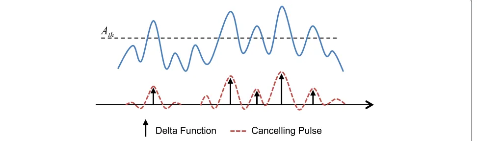
A basic diagram of the PC process considered in this work is sketched in Figure 1. Its principle is to generate can-celling pulses at the time instants where the peaks higher than the predetermined threshold are found. The gener-ated pulses are linearly scaled and rotgener-ated with appropri-ate phase shift such that after their addition the original signals have the peaks reduced to the threshold [17].
2.1 Peak-cancelling process
To perform peak cancellation on the complex baseband signal, the target signal should be oversampled as the Nyquist-rate-sampled signals cannot correctly represent the actual amplitude of peaks of the continuous-time sig-nals [3]. The discrete complex baseband signalsnhas the general form of:
sn=rnejθn, (1) where rn and θn represent the amplitude and phase, respectively, at thenth time instant. Suppose that there areNppeaks that are larger than the predefined threshold
Athwithin a given time periodT, and letρ1,ρ2,· · ·,ρNp denote the corresponding successive peaks observed at the time instants n1,n2· · ·,nNp, respectively. Let gn denote the impulse response of the cancelling pulse cen-tred at n = 0, i.e.g0 representing its maximum value.
Then, theith peak cancelling pulse at the time instantni, wherei∈ {1,· · ·,Np}, is expressed as:
p(ni)=rni−Ath
Figure 1A simplified block diagram of the PC process.
where pn is all the combined cancelling pulses located at the time instant ni. If we ignore the change of the amplitude and average power due to the addition of all the cancelling pulses, Ath is the maximum ampli-tude after peak cancellation. In what follows, we refer to the corresponding PAPR determined by Ath as a
target PAPR.
2.2 Effect of the cancelling pulse
The impulse response of the cancelling pulse gn deter-mines the resulting OOB radiation. In general,gn should be compliant to the spectral mask of a given target stan-dard. Suppose thatsn is the oversampled version of the band-limited signal and letJdenote the oversampling fac-tor such that the˜skJrepresents the samples at the Nyquist rate for an integerk.
The resulting signalsnis then expressed as:
sn=
k
˜
skJhn−kJ, (4)
where hn is the corresponding impulse response of the pulse-shaping filter, and the summation is over the range of k where the impulse response has a non-negligible effect. It is worth mentioning that even though the OFDM signal is not explicitly shaped by a filter, we can still find an equivalent form [25] to represent the virtual pulse-shaping filter. Therefore, Equation 4 also applies to the conventional OFDM signals.
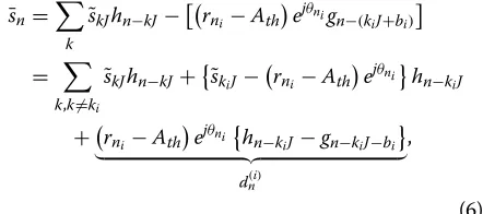
Now we consider the scenario where one peak ρi is detected and subtracted by a cancelling pulsep(ni). It then follows that:
Suppose that the peak position is precisely given at
ni = kiJ +bi, whereki andbi are some integers. Then, Equation 5 is rewritten as:
¯
which indicates that a proper design ofgn will avoid the out-of-band emission, but we still observe that distortion componentd(ni)will affect all the other sampling instants. This distortion component can be nullified only ifgnis set equal tohn and the peak position occurs at the Nyquist point, i.e.hn−kiJ =gn−kiJ−bi.
In other words, if the cancelling pulsegnis identical to
hn, then no out-of-band regrowth will occur as the sig-nal power is confined inside the pass-band ofhn. In fact, the clipping and filtering approach presented in [13] cor-responds to this special case wheregnis the periodic sinc function [25]. Since the periodic sinc function has non-negligible impulse response over entire OFDM symbol, it causes considerable peak regrowth. Therefore, in prac-tice, we wish to choosegnsuch that its side lobe (in time domain) vanishes rapidly, and yet, its frequency response has acceptable out-of-band emission in terms of adjacent channel leakage ratio (ACLR).
2.3 Design of the cancelling pulse
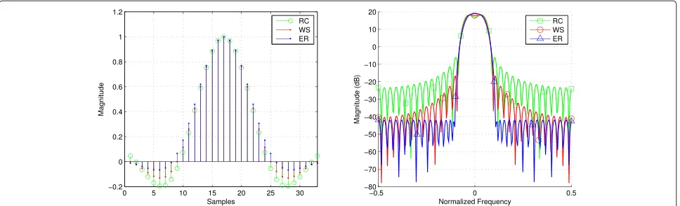
Figure 2Performance comparison of the three different cancelling pulses designed based on different FIRs.The left hand side figure shows their impulse responses, whereas the right hand side figure shows the corresponding frequency responses. RC, raised cosine; WS, windowed sinc; ER, equal ripple.
shorter impulse response results in lower in-band dis-tortion, but it will cause an increasing amount of out-of-band radiation that may violate the specified spectral mask. Therefore, careful design of the cancelling pulse is essential.
However, there exists no solid algorithm or closed-form deviation for finding the best cancelling pulse, and thus, exhaustive attempts are necessary to find the suit-able one for a specified signal and to satisfy the design requirements. For instance, three different filters (can-celling pulses) of the same length are illustrated in Figure 2 with their respective impulse response and frequency response. Here, the windowed sinc (WS) is obtained by multiplying Kaiser window to sinc function. The raised cosine (RC) and sinc are both Nyquist filters as can be seen from the left hand of the figure. The equal ripple (ER) filter is obtained by the well-established Parks-McClellan algorithm [26] which minimizes the error in pass and stop bands by employing Chebyshev approximation. The
performance of the peak cancellation based on the three cancelling pulses is demonstrated in Figure 3 using numerical simulation, where a WCDMA signal is used as its test signal. In this figure, as a practical measure for PAPR, we adopt the complementary cumulative dis-tribution function (CCDF) of the instantaneous power normalized by its average power.
From the left hand side of Figure 3, we observe that sim-ilar PAPR performance is achieved. However, comparison of the power spectra in Figure 3 with their corresponding frequency responses in Figure 2 reveals that the frequency response of the cancelling pulses has the dominant effect on the resulting spectrum after peak cancellation.
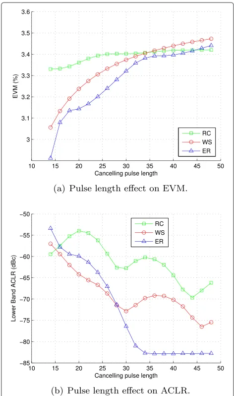
The effects of pulse length on the in-band distortion (i.e. EVM) and out-of-band distortion (i.e. ACLR) are reported in Figure 4a,b, respectively. The measurement of EVM and ACLR follows the 3rd Generation Partner-ship Project (3GPP) frequency division duplexing (FDD) WCDMA downlink specification [27]. We have concluded
Figure 4Effect of different pulse length.(a)Pulse length effect on EVM.(b)Pulse length effect on ACLR. RC, raised cosine; WS, windowed sinc; ER, equal ripple; EVM, error vector magnitude; ACLR, adjacent channel leakage ratio.
in the last subsection that a longer pulse introduces more symbol errors to the target signal, and this is val-idated by Figure 4a. On the other hand, it can be easily grasped by inspection of Figure 4b that ACLR reduces with longer cancelling pulse length. However, the curves shown in the figure have some fluctuations. This can be understood by inspecting Figure 5, where the impulse response for a typical low-pass filter is shown. Trun-cation length of the impulse response also affects the shape of the resulting frequency response. For instance,
L1 has worse out-of-band attenuation than L3 but may
be better thanL2, becauseL2has non-zeroes at the head
and end. This heuristic observation reveals a basic clue for choosing the cancelling pulse length: the cancelling pulse should be as short as possible to minimize the
distortion but should be long enough to give admissible ACLR.
It can also be observed from Figure 4a,b that the can-celling pulse generated by an equal ripple filter gives the best performance both in terms of EVM and ACLR. Bet-ter EVM performance is due to the lower side lobe in time domain, and lower ACLR is due to higher out-of-band attenuation of the cancelling pulse, as can be seen from Figure 2. It can also be seen from Figure 4a that even though the raised-cosine filter completely conforms to the pulse-shaping filter for WCDMA signal, it shows worst performance when the cancelling pulse length is short. This is mainly due to the distortion effect and the high sidelobe of the raised-cosine filter. In general, design-ing cancelldesign-ing pulse with Parks-McClellan algorithm leads to better performance than other filter types that are frequently found in the literature.
3 Hardware implementation of peak cancellation
From this section and later, we focus on efficient imple-mentation of PC by hardware. We first introduce the conventional approach for the implementation of PC as well as its alternative method, which is followed by the description of the proposed PC as well as their detailed implementation issues.
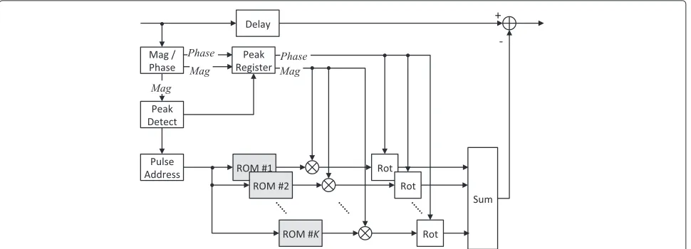
3.1 Conventional implementation: scheme 1
A conventional scheme for implementing the PC [28], which we refer to as ascheme 1in what follows, is shown in Figure 6. The instantaneous magnitude and phase of the complex signal are computed with coordinate rotation digital computer (CORDIC) algorithm. The ‘Peak Detect’ block, which contains some registers and comparators, identifies the peak magnitude higher than the thresh-old. When a peak is detected, the corresponding phase and the magnitude amount higher than the threshold are latched. These values are used to scale and rotate the nor-malized real cancelling pulses, and these operations are accomplished by multiple CORDIC cores.
The cancelling-pulse generator block contains one counter, which is directly connected to the address port of the read only memory (ROM). The pre-determined can-celling pulse, which is compliant with the target signal spectrum, is stored in the ROM. The counter will be trig-gered as soon as one peak is found, and it is reset when it counts to the length of cancelling pulseL.
Figure 5An example of typical impulse response of cancelling pulse with various truncation lengths.
still on, the second and third generators will be triggered to generate the second and third cancelling pulses. If the fourth peak is detected when ROM 1 is free, the first gen-erator will be reused to generate the fourth cancelling pulse. In summary, when the previous cancelling-pulse generator is triggered and the next peak is found, the next cancelling-pulse generator will be triggered in sequel. This successive process continues until no peak higher than the threshold is found. All the outputs of the cancelling-pulse generators are summed and finally subtracted from the delayed original signal.
It becomes clear that the resource complexity of this scheme is bounded by the number of available cancelling-pulse generators. Note that whether this scheme can can-cel all the peaks in one pass or not depends on the specific parameters such as the required pulse length, targeted PAPR and the number of cancelling-pulse generators. It is easy to see that the generators in the upper side of Figure 6
have a higher probability to be used while the cancelling-pulse generators in the bottom may be idle most of the time. Therefore, some compromise is necessary to deter-mine how many cancelling-pulse generators are used. As a rule of thumb, five or six cancelling-pulse generators are enough when a reasonable threshold value is assumed, as the average number of the peaks above the thresh-old monotonically decreases as the threshthresh-old increases [3]. However, since the number of peaks itself is a ran-dom variable, with the fixed number of pulse generators, a failure to peak cancellation may occasionally happen. In this case, some iterative processing structure should be introduced, which may lead to increasing latency.
3.2 Conventional implementation: scheme 2
To overcome the issue of a peak cancellation failure, an alternative implementation scheme [29], which we refer to asscheme 2, can be applied. Let us rewrite Equation 3 as:
Figure 7Principle of multiple cancelling pulse generation.
¯
sn=sn− Np
i=1
rni−Ath
·δ (n−ni)ejθni∗gn, (7)
wheregnserves as the coefficients (impulse response) of an FIR filter and∗denotes the convolution operation. The cancelling pulses can be thus generated by propagating the delta function train to this filter, and this principle is illustrated in Figure 8 and its hardware implementation is given in Figure 9.
Similar to the first scheme, a CORDIC core is used to compute the magnitude and phase of the signal. The ‘Pulse Gen’ block outputs a sample which is properly scaled and rotated when a peak is detected. The resulting delta func-tion train is complex-valued. It is easy to see from Figure 9 that the resource complexity relies primarily on the fil-ter, while the complexity of its counterpart in Figure 6 depends on the number of CORDIC cores. Implement-ing an FIR filter requires a large number of multipliers, which makes the scheme 1 preferable as it consumes less resources.
In summary, the first scheme has lower complexity in terms of fewer multipliers but has the problem of peak generation failure. The second scheme is easier to imple-ment but has higher resource complexity due to the use of FIR filter. In order to cope with the peak generation failure, however, the first scheme may require more iter-ations which in turn increase the complexity several fold. In this sense, the second scheme that has a fixed hardware overhead is preferred.
3.3 The proposed peak cancellation
As can be observed from Figure 7, a sum of multiple overlapped pulses forms the final pulse when intensive peaks occur. The tails of the previous pulses may hap-pen to be added in-phase to the peaks in sequel, result-ing in less effective peak reduction. Inspired by these observations, we proposed a novel approach of peak cancellation. The principle of the proposed approach is illustrated in Figure 10. Instead of generating complete cancelling pulses stored in the ROMs as the one shown in Figure 6, the proposed scheme generates truncated
Figure 9Architecture of conventional hardware implementation of peak cancellation - scheme 2.FIR, finite impulse response.
cancelling pulses when they are overlapping with each other. More specifically, when the interval of two con-tiguous peaks is detected to be less than the predefined cancelling-pulse length, the generation of the first can-celling pulse terminates in the middle of the interval and immediately triggers the second cancelling pulse. Since this scheme reduces the length for overlapping cancelling pulses, lower in-band error can be expected in view of the observation given in the Section 2.3.
However, as can be seen from Figure 10, the cancelling pulses show obvious discontinuity which would produce substantial band emission. To mitigate the out-of-band emission, a filter can be applied to smooth the dis-continuities, and the resulting waveform of the smoothed cancelling pulse is also denoted by the dashed curve in Figure 10. In our method, we use a simple moving aver-age filter as a smoothing filter, with which the out-of-band spurious level caused by non-continuous cancelling pulses can be reduced. Note that the smoothing filter is actu-ally optional as we can still obtain a moderate out-of-band emission without it, considering that the occurrence of high peaks is a rare event [3]. The smoothing filter is only necessary in the ACLR-prior circumstance. Normally,
Figure 10Principle of the proposed peak cancellation approach.
a short-length smoothing filter is adequate to further improve the ACLR performance. As the filter length is very short, it gives negligible effect on EVM.
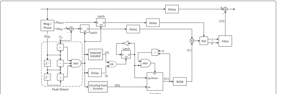
3.4 Implementation of the proposed peak cancellation We now describe the hardware implementation aspects of the proposed scheme. A detailed block diagram of the proposed scheme is given in Figure 11. Some example waveforms of the internal signals labelled in Figure 11 are plotted in Figure 12.
Similar to the previous schemes, a CORDIC core is used to compute the instantaneous magnitude and phase of the signal. The ‘Peak Detect’ block, which contains some reg-isters and comparators, outputs a ‘1’ when a magnitude peak is found, as shown in the second plot in Figure 12. The output of the ‘Peak Detect’ block is connected to the enable ports of the two latches which store the magnitude and phase of the corresponding peak. The ‘Interval Loca-tor’ block generates a ‘1’ in the middle of two peaks when the interval of these peaks is less than the cancelling-pulse length. The outputs of ‘Interval Locator’ and ‘Peak Detect’ (I) and (II) are combined with an OR gate. A ‘Delay’ block is used to align these two signals as the ‘Interval Locator’ has a fixed delay. The ‘Cancelling Pulse Duration” block produces enable signal (III) for the counter which outputs the address of the ROM. The counting direction of the counter is controlled by a latch output which is reversed when triggered by the output of the OR gate. Operation of these signals can be easily seen from the second and third plots in Figure 12.
The ROM output (V) is then scaled and rotated by the latched magnitude and phase to form the cancelling pulses and fed to the FIR filter. The smoothed cancelling pulses (VI) are subtracted from the delayed original signal to form the PAPR-reduced signal. It should be noted that the four ‘Delay’ blocks shown in Figure 12 do not neces-sarily indicate that the delay values for these blocks are identical.
Figure 11Hardware circuit of the proposed PC scheme using FPGA.ROM, read only memory.
Figure 9. Thus, it has less hardware complexity, even though both of them contain two CORDIC cores.
4 Performance evaluation of the proposed peak
cancellation
In this section, the experimental results for implementa-tion with FPGA are reported. We will compare the hard-ware complexity (in terms of resource utilization) of the proposed PC and conventional PC first. This is followed by the experimental results using a standard-conforming long-term evolution (LTE) signal as well as multi-standard signals.
4.1 Experiment description
The implementation is carried out using an FPGA eval-uation board VC707, which contains a Xilinx Virtex-7
XC7VX485T-2FFG1761C device. The test WCDMA/LTE signal (baseband IQ) is generated by Matlab on the computer and is stored in a bank of RAMs in the FPGA as the signal source. The output of peak cancellation is captured by a series of integrated logic analyzers (ILAs) in parallel, which is arranged in a time-interleaved manner so as to receive the signal of long length. This signal is then transferred to computer through USB port and circularly shifted to align with the original signal and is analysed by Matlab.
A 245.76-MHz clock is synthesized by the on-chip mixed-mode clock manager (MMCM), which uses the on-board 200-MHz oscillator as the reference. The clock is set to integer times (64 times in our example implementa-tion) of 3.84 MHz, targeting the specification of the 3GPP WCDMA and LTE signals.
magnitude multiplying the complex cancelling pulse in I/Q) so that the total consumption of multipliers is 17.
4.2 Resource utilization
The FPGA resource utilization, which is evaluated with Resource Estimator using post-mapping, for the three PC approaches introduced are summarized in Table 1 where the scheme 1 is operated either without iteration or with one iteration. Only primary resources such as the slices and look-up tables (LUTs) are listed here, since they are generic for any FPGA, while the other resources used for our test (primarily block RAMs and IOs for ChipScope) are specific to the FPGA board and thus are not taken into consideration.
In scheme 1, the PC is comprised of four cancelling-pulse generators, and therefore, four RAMs are used to store the cancelling pulse and accordingly four CORDIC cores are needed. One can see that with a single iter-ation, the hardware resource of scheme 1 is roughly doubled. It is obvious that all of the three schemes con-sume only a small portion of the resources such as flip flops (FFs) and slice LUTs. The conventional scheme 2 costs more multipliers. This is because it requires imple-menting the FIR filter to generate the cancelling pulses of equivalent length. For circuit integration, the multi-pliers are most concerned as they generally cost more power and take up larger area than other simple arith-metic elements. In this sense, the proposed PC is rather cost effective as it consumes fewer multipliers. Although the conventional scheme 1 without iteration requires even
Table 1 FPGA resource utilization table
FFs Slice LUTs DSP48 RAM
(Multipliers)
Proposed 3,920 3,439 17 1
Conventional scheme1 3,354 3,117 15 4
(no iteration)
Conventional scheme1 6,785 6,341 30 8
(one iteration)
Conventional scheme2 5,749 5,383 171 0
Available in FPGA 607,200 303,600 2,800 1,030
FF, flip flop; LUT, look-up table.
4.3 Test results using LTE signals
The rest of the paper is devoted to the comparison of the three approaches in terms of in-band distortion, out-of-band emission and realizable PAPR.
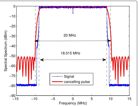
The applied LTE signal is a 16-QAM OFDM signal with 1,200 subcarriers within 18.015-MHz occupied band-width and 20-MHz channel bandband-width. The basic sam-pling rate for such signal is 30.72 MHz since the FFT size is 2,048. The PC for LTE signal is operated at 245.76 MHz which represents an oversampling rate of 8. The sig-nal spectrum and cancelling-pulse spectrum are demon-strated in Figure 13. The cancelling pulse used here was designed by Chebyshev approximation, as described in Section 2.3.
4.3.1 Peak power reduction capability comparison for different PC schemes
In what follows, we evaluate the CCDF of the normal-ized instantaneous power after employing the PC schemes considered in this work.
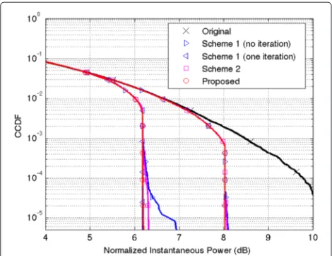
The CCDF plots of the signal with the proposed PC and the two conventional PC schemes are demonstrated in Figure 14 where the target PAPR values are set as 6 and 8 dB. As can be seen from the figure, the conventional scheme 1 without iteration exhibits high peaks due to
Figure 14CCDF comparison in terms of normalized
instantaneous power for different PC schemes with the target PAPR of 6 and 8 dB.CCDF, complementary cumulative distribution function.
the cancelling peak generation failure under the condi-tion that only four ROMs are made available for this purpose. This problem can be solved by adding a sin-gle iteration, but this doubles the required resources as can be seen from Table 1. The conventional scheme 2 outperforms the scheme 1 without iteration, at a cost of increasing hardware complexity. The proposed PC, on the other hand, achieves performance comparable to the scheme 1 with iteration, even with lower hardware complexity.
Considering the fact that the scheme 1 may not nec-essarily achieve a target peak power reduction perfor-mance without iteration, the experiments hereinafter will be focused exclusively on the proposed scheme and con-ventional scheme 2.
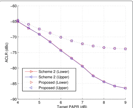
An important factor for evaluating the performance of a PAPR-reduction technique is the actually realizable PAPR. It is well known that the CAF causes an unavoid-able peak power regrowth, and this will make the precise control of PAPR challenging without resorting to increas-ing complexity such as iterative use of CAF [20], which may also introduce a prohibitive amount of latency. In contrast, the peak power achieved by PC schemes can reduce the effect of the peak power regrowth and thus achieve the PAPR close to the target PAPR. Figure 15 compares the peak power reduction capabilities of the schemes 2 and the proposed scheme. In this figure, in response to the target PAPR, the actual threshold values of the normalized instantaneous power at given specific CCDF of 10−4and 10−5are plotted as a realizable PAPR. It is observed that the proposed scheme outperforms the scheme 2 from the viewpoint of PAPR reduction as well.
Figure 15Realizable PAPR versus target PAPR for LTE signal.The realizable PAPR is defined as the corresponding threshold-normalized instantaneous power values measured at the CCDF of 10−4and 10−5. PAPR, peak-to-average power ratio.
4.3.2 In-band and out-of-band distortion comparison for different PC schemes
The constellation plots of the user data, which are 16-QAM signal, with target PAPR of 5 and 7 dB, are delin-eated in Figure 16. The pilot points (reference signal) in red, which is QPSK, are used to rotate, rescale and equal-ize the user data. It can be inspected from the figure that, for a target PAPR of 5 dB, the constellation of the user data is rather dispersive.
The measured EVM and ACLR with different target PAPRs are demonstrated in Figures 17 and 18, respec-tively. It can be inspected from the figures that the pro-posed scheme yields lower in-band distortion (in terms of lower EVM) and higher out-of-band distortion (in terms of higher ACLR). This stems from the fact that since the proposed method generates shorter cancelling pulses, it can essentially reduce the in-band distortion in time domain but with the broader side lobes in frequency domain, as discussed in Section 2. Also, even though the proposed scheme has higher out-of-band emission, the observed ACLR with this parameter setting is still satisfactory for practical applications.
4.4 Test results using various signals
Finally, multiple tests have been performed to validate the proposed scheme for a more general framework with multi-carrier and multi-standard signals.
4.4.1 Carrier-aggregated LTE signals
Figure 16Constellation plots of user data.(a)When target PAPR = 5 dB.(b)When target PAPR = 7 dB. PAPR, peak-to-average power ratio.
PAPR is set to 7 dB which can yield reasonable EVM. The resulting CCDF is plotted in Figure 19a to show the effectiveness of the proposed scheme. The spectral den-sity plots provided in Figure 19b show that, with the given cancelling pulse, the proposed scheme yields very lim-ited spectral regrowth. The EVMs for the respective CCs under the condition of different realizable PAPRs are plot-ted in Figure 20. We observe that the EVM curves for
Figure 17EVM versus target PAPR for LTE signal.EVM, error vector magnitude; PAPR, peak-to-average power ratio.
different CCs almost overlap with each other, indicating the effectiveness of the proposed PC under the system operated with multiple carrier frequencies.
4.4.2 Multi-standard signals
The second test uses a multi-standard signal, which con-tains three WCDMA carriers and a 20-MHz LTE carrier, where the two standard signals are spaced by 40 MHz. The WCDMA signal used in this paper is generated following the specification defined by 3GPP test model 3, for which 64 users (16-QAM) are multiplexed in dedicated physical data channel (DPDCH) to form the 3.84 Mc/s chip rate. The WCDMA chip is oversampled 64 times, and the PC is operated at a corresponding sampling frequency of 245.76 MHz.
Figure 19The performance comparison of PC for three-carrier LTE-Advanced signal.(a)CCDF when target PAPR is set to 7 dB.(b)
The power spectral density plots when target PAPR is set to 7 dB. CCDF, complementary cumulative distribution function; PC, peak cancellation.
Figure 20EVM of each LTE-Advanced component carrier.EVM,
error vector magnitude; PAPR, peak-to-average power ratio.
The resulting CCDF and power spectral plots are given in Figure 21a,b, which demonstrate the adaptability of the proposed PC to the signal with non-contiguous spec-trum. The proposed scheme, with a realizable PAPR of around 7 dB, can meet the imposed requirement on power spectrum well as can be inspected from Figure 21b.
5 Conclusions
In this paper, the peak cancellation technique as a gen-eral purpose PAPR reduction has been addressed. The design issues of cancelling pulses that determine the per-formance of PC have been also discussed. Our main focus was on their FPGA implementation with a special consid-eration on the hardware complexity. A novel PC scheme with notably low-hardware complexity has been also pre-sented. The experimental results using various signals have demonstrated the validity of the proposed approach.
Figure 21The performance comparison of PC for the aggregated
in OFDM signals. Commun. IEEE Trans.49(2), 282–289 (2001) 4. SH Han, JH Lee, An overview of peak-to-average power ratio reduction
techniques for multicarrier transmission. Wireless Commun IEEE.12(2), 56–65 (2005)
5. T Jiang, Y Wu, An overview: peak-to-average power ratio reduction techniques for OFDM signals. Broadcasting IEEE Trans.54(2), 257–268 (2008)
6. Y Rahmatallah, S Mohan, Peak-to-average power ratio reduction in OFDM systems: a survey and taxonomy. Commun. Surveys Tutorials IEEE.15(4), 1567–1592 (2013)
7. O Väänänen, J Vankka, K Halonen, Simple algorithm for peak windowing and its application in GSM, EDGE and WCDMA systems. IEE Proc. Commun.152(3), 357–362 (2005)
8. W-J Kim, K-J Cho, SP Stapleton, J-H Kim, Doherty feed-forward amplifier performance using a novel crest factor reduction technique. Microwave Wireless Components Lett. IEEE.17(1), 82–84 (2007)
9. RW Bauml, RFH Fischer, JB Huber, Reducing the peak-to-average power ratio of multicarrier modulation by selected mapping. Electron. Lett. 32(22), 2056–2057 (1996)
10. SH Müller, RW Bäuml, RFH Fischer, JB Huber, OFDM with reduced peak-to-average power ratio by multiple signal representation. Ann. Des Té, lécommunications.52(1-2), 58–67 (1997)
11. RJ Baxley, GT Zhou, Comparing selected mapping and partial transmit sequence for PAR reduction. Broadcasting IEEE Trans.53(4), 797–803 (2007)
12. X Li, LJ Cimini, Effects of clipping and filtering on the performance of OFDM. Commun. Lett. IEEE.2(5), 131–133 (1998)
13. H Ochiai, H Imai, Performance analysis of deliberately clipped OFDM signals. Commun. IEEE Trans.50(1), 89–101 (2002)
14. R O’Neill, LB Lopes, inIEEE International Symposium on Personal, Indoor and Mobile Radio Communications (PIMRC’95). Wireless: Merging onto the Information Superhighway. Envelope variations and spectral splatter in clipped multicarrier signals. vol. 1 IEEE (Toronto, 1995) 71–75 15. HN Mistry, Implementation of a peak windowing algorithm for crest
factor reduction in WCDMA Master’s thesis, School of Engineering Science-Simon Fraser. University, Burnaby, BC, Canada, (2006) 16. M Pauli, H-P Kuchenbecker, Minimization of the intermodulation
distortion of a nonlinearly amplified OFDM signal. Wireless Personal Commun.4(1), 93–101 (1997)
17. T May, H Rohling, inIEEE Vehicular Technology Conference (VTC98). Reducing the peak-to-average power ratio in OFDM radio transmission systems, vol. 3 (IEEE Ottawa, 1998), pp. 2474–2478
18. L Dan, Y Xiao, W Ni, S Li, Improved peak cancellation for PAPR reduction in OFDM systems. Commun. IEICE Trans.E93-B(1), 198–202 (2011) 19. H-B Jeon, J-S No, D-J Shin, A new PAPR reduction scheme using efficient
peak cancellation for OFDM systems. Broadcasting IEEE Trans.58(4), 619–628 (2012)
20. J Armstrong, Peak-to-average power reduction for OFDM by repeated clipping and frequency domain filtering. Electron. Lett.38(5), 246–247 (2002)
21. Y Wang, Z Luo, Optimized iterative clipping and filtering for PAPR reduction of OFDM signals. Commun. IEEE Trans.59(1), 33–37 (2011) 22. BS Krongold, DL Jones, inProceedings of 2003 IEEE International Conference
on Acoustics, Speech, and Signal Processing (ICASSP ’03). PAR reduction in OFDM via active constellation extension, vol. 4, (April 2003), pp. IV–525–8 23. J Tellado, JM Cioffi, PAR reduction in multicarrier transmission systems.
ANSI Document, T1E1.4 Tech. Subcommittee.4, 1–14 (1998)
29. CA Azurdia-Meza, K Lee, K Lee, PAPR reduction by pulse shaping using Nyquist linear combination pulses. IEICE Electron. Express.9(19), 1534–1541 (2012)
Submit your manuscript to a
journal and benefi t from:
7Convenient online submission 7Rigorous peer review
7Immediate publication on acceptance 7Open access: articles freely available online 7High visibility within the fi eld
7Retaining the copyright to your article