Innovative Design and Analysis of Support Arrangement for Double
Walled Tank Containing Primary Sodium
S.K.Pandey, B.C.Sati, R.Srinivasan, P.Selvaraj, P.Chellapandi and S.C.Chetal
Indira Gandhi Centre for Atomic Research, Kalpakkam-603102, India
ABSTRACT
In Prototype Fast Breeder Reactor, an on line purification circuit for primary sodium is provided. The purification circuit comprises an electromagnetic pump, priming tank, economizer and cold traps. The priming tank of purification circuit is located in the down streamside of its electro magnetic pump. Since it contains radioactive primary sodium, it is not freely accessible. Priming tank is a vertical tank with torispherical dished ends on both top and bottom. The total weight of priming tank, including the sodium in it is 1.6 t. It is provided with double envelope to avoid release of radioactive sodium in reactor control building in case of leak in tank. Nitrogen is filled in annular space to provide an inert atmosphere. The material of the priming tank and the double envelope is SS 304 LN. The normal operating temperature of the priming tank is 400°C. During SGDHR the temperature rises to 540° C and reduces to 200° C during fuel handling condition. The tank is insulated to reduce the heat loss to surroundings. This paper aims at arriving at a support arrangement for the tank with the features (i) weight shall be transferred to support from main shell (ii) main shell shall be covered fully by double envelope, (iii) split flange with a conical shell in between the double envelope and support flange from thermal stress consideration, (iv) temperature at bolt location is less than 70° C and (v) easy manufacturing.
To meet the above features, a conical support shell is designed to support the priming tank. The conical support shell is attached to the priming tank through a ring. The double envelope is also attached to the ring. Inside diameter and shell thickness of the tank main shell are 750 mm and 8 mm respectively. Based on parametric study, the height of the cone and height of insulated portion of cone from the junction are arrived at. This supporting arrangement is analysed for dead load and thermal loads during normal operation, fuel handling condition and SGDHR condition. Design check for the tank is carried out as per RCC-MR 2002 procedure for class-1 component. Two governing events namely loss of steam water system occurring 47 times in design life and the offsite power failure occurring 160 times in design life are considered for the analysis. The operating time for the tank at 540° C during SGDHR (corresponding to the two events) is ~1480 h. Since this exceed the creep cross over curve limit of RCC-MR, the hot junction between the cone and cylinder is analysed for creep fatigue damage.
Parametric study is carried out using finite element model with axi-symmetric thin shell element in CAST-3M FE software. The cylindrical shell of priming tank, along with the double envelope and support shell and flange are modeled. After finalizing the height of the cone and insulation height, detailed analysis using 8 noded axi-symmetric solid elements is carried out to get the peak stresses at the junctions needed for creep-fatigue damage evaluation. The creep-fatigue damage is found to be negligible. The creep damage at the junction of conical support shell to ring attached to main tank is found to be 0.074, which is acceptable. The structural integrity of proposed configuration is thus confirmed by analysis.
INTRODUCTION
During reactor operation, impurity concentration of the primary sodium changes. Impurities in sodium may cause problems like corrosion of structural materials, plugging of flow passages, and alteration in mechanical properties of metals in contact and sodium oxide precipitation. Hence it is required to purify sodium at continuous or at regular interval. The oxygen level in sodium is to be kept very low (~2 ppm). In PFBR an on line purification circuit for primary sodium is provided. The purification circuit comprises an electromagnetic pump, priming tank, economizer and cold traps. The priming tank of primary sodium purification circuit (PSPC) is located in the down streamside of its EM pump. The main functions of the tank are (i) to prime the EM pump and (ii) to avoid any siphoning of the sodium from reactor vessel in case of leak in purification circuit or in the event of EM trip. Since it contains radioactive primary sodium, it is categorized as safety class –1. Further the tank is not freely accessible during operation. This tank is Primary tank is a vertical tank with torispherical-dished ends on both top and bottom. It is provided with double envelope to avoid release of radioactive sodium in case of leak in tank. It is supported at the middle. Different options studied for supporting the priming tank are described below:
(i) The supporting flange is directly attached to the priming tank (Fig.1). But in this option (option-1) the double envelope is not covering the main support location hence not favored. Also due to conduction the
temperature at the bolt location is becoming higher otherwise a large flange is required, which is not feasible.
(ii) In the second option it is proposed that the double envelope is covering the tank fully and the tank is resting on dished end of the double envelope (Fig. 2). Double envelope is supported through a flange. This arrangement involves complex interaction between tanks and double envelope, particularly under seismic loading, hence discarded.
Hence this note aims at proposing an alternative support arrangement for priming tank (option-3) with the following features.
• Weight shall be transferred to support from main shell. • Main shell shall be covered fully by double envelope.
• Split flange with a conical shell, in between the double envelope and flange from thermal stress consideration.
• Temperature at bolt location is less than 70° C. • Easy manufacturing.
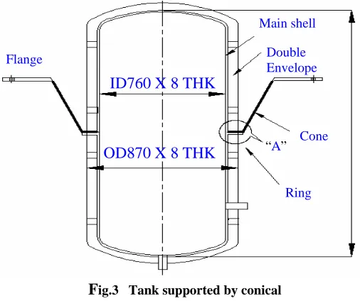
To meet the above features, a conical support shell is proposed to support the priming tank. The conical support shell is attached to the priming tank through a ring. The double envelope is also attached to the ring (Fig. 3). The above proposed supporting arrangement is then analysed for dead load and thermal loads during normal operation, fuel handling condition and SGDHR condition. Parametric study has been carried out to finalize the geometric details of the junction which will meet the design criteria especially 3Sm limit. For each case, temperature distribution has been obtained from detailed thermal analysis [1]. Finally, creep-fatigue damage is assessed for the junction and the support configuration meeting all the criteria is recommended.
INPUT DATA
2450
OD 750 X 8 THK
OD 870 X 3 THK
Fig. 1 Supporting flange directly welded To main shell – option 1
OD 750 X 8 THK
OD 870 X 3THK
Fig.2 Tank supported by dished end of Double envelope – option 2
2450
Main shell
Double Envelope Flange
Cone “A”
Ring
ID760 X 8 THK
OD870 X 8 THK
F
ig.3 Tank supported by conical Shell - option 3The inside diameter of the tank main shell is 750 mm and its thickness is 8 mm. The outer diameter of the double envelope is 870 mm and its thickness is 3 mm. Thickness of the ring is 15 mm and that of the flange is 20 mm. The height of the cone is kept as a parameter varying from 300 mm – 600 mm. The insulation height is also varied as a parameter (100 mm – 300 mm). Ultimately the component is bolted through a flange at the upper end of the conical shell.
The material of the priming tank and the double envelope is SS 304 LN. The normal operating temperature of the priming tank is 400°C. During SGDHR the temperature rises to 540° C, and reduces to 200° C during fuel handling condition. The physical properties of SS 304 LN at 400° C are [2] used. The modulus of elasticity is 1.68E+5 MPa and Poisson’s ratio is 0.3. The coefficient of thermal expansion is 17.8E-6 mm/mm/K and the allowable stress intensity (Sm) is 107 MPa.
LOADING
The total weight of priming tank, including the sodium in it is ~1.6 t. For analysis the weight is conservatively considered as 2 t. The temperature distribution on the tank, double envelope, support-shell to tank junction and support shell are taken from thermal hydraulic studies [1].
DESIGN CRITERIA
Design check for the tank is carried out as per RCC-MR 2002 procedure for class-1 component. Two governing events namely loss of steam water system occurring 47 times in design life [3] (8.5 h for decay heat removal each time [4]) and the offsite power failure occurring 160 times in design life time (6.75 h for decay heat removal each time) are considered for the analysis. Hence the operating time for the tank at 540° C during SGDHR is ~1480 h. The temperature limit corresponding to 1500 h obtained from creep cross over curve for SS304 LN is ~ 485° C. As the temperature at the tank shell junction is expected to cross this value during SGDHR, the creep is considered to be significant at this junction. Since the temperature near the flange junction is much less, the creep effects are negligible at the flange junction.
However, the time independent stress intensity (Sm) is found to be lower than the time dependent stress intensity (St) corresponding to 540° C for 1500 h. Hence the following stress limits are checked.
Pm < Sm
PL + Pb < 1.5 Sm Range of (PL + Pb + ∆Q) < 3.0 Sm
Further creep fatigue damage is assessed by detailed analyses for the final geometry after finalizing the height of the cone and insulation height, which meet the above limits.
ANALYSIS AND RESULTS
Parametric Study to Meet Stress Limits
For finalizing the major dimensions, parametric study has been carried out by varying the height of the cone and the insulation region. A portion of conical shell in the upper end is left bare (without insulation). The aim of parametric study is to arrive at the insulated and bare lengths of the cone which can meet the following requirements:
(i) nearly linear gradient near the hot junction and
(ii) lower temperature at the top flange junction so as to limit the temperature at the bolt location. For each case temperature distribution has been obtained by detailed thermal analysis as reported in ref [1]. The cylindrical shell of priming tank, along with the double envelope and support shell and flange are modeled using axisymmetric thin shell elements in CAST-3M FE software, developed by CEA France. Finite Element model is shown in fig. 4. The outer periphery of flange is fixed only in vertical direction, as it is free to move in radial direction (oblong bolt holes are provided to cater radial thermal expansion). Analyses have been carried out by varying insulation lengths for a fixed cone height. Finally a cone height of 600 mm with insulation up to 300 mm above the tank junction have been arrived at for which case the stress limits are found to meet with comfortable margin as shown
Fig.4 FE model using axisymmetric thin shell element
Junction-A Junction-B
below.
Table: 1 Stress intensity under dead load
Description Axial stress (MPa) Hoop stress (MPa) Stress Intensity (MPa)
Membrane
1.1 1.1 1.1
Membrane +
bending 14.3 4.9
Membrane – bending
-12.1 -2.6 14.3
Pm = 1.1 MPa < Sm
PL + Pb = 14.3 MPa < 1.5 Sm
The junction A between ring and cone (Fig. 3&4) is the critical location, at which the membrane and bending stresses in the axial direction are -5 MPa and 121 MPa respectively for thermal loading under SGDHR condition. For the same loading the membrane and bending stresses in the hoop direction are 11.2 MPa and 37.1 MPa respectively. The stress components during SGDHR are conservatively taken as the range (without subtracting the corresponding value during normal operation or fuel handling) as there is no case of sign change in the stress components.
Table: 2 Secondary stress intensity range
Description Axial stress (MPa) Hoop stress (MPa) Secondary stress intensity range -∆Q (MPa)
Membrane + bending
116 48
Membrane –bending -126 -26
126
Fig.5 Finite element model using 8 noded axisymmetric solid element
Fig.6 Temperature (deg. C) distribution on the priming tank during SGDHR condition
58
106
152
174
219
265
310
355
401
446
491
540
No variation in the primary stresses is expected as the weight loading is not changing. However, the absolute value of primary membrane plus bending stress intensity (14 MPa) itself is small and hence the range of (PL + Pb + ∆Q) is less than 3.0 Sm.
Creep-Fatigue Evaluation for the chosen configuration
For the chosen configuration of support, the structure is modeled with 8 noded axi-symmetric solid elements to get the peak stresses at the junctions needed for creep-fatigue damage evaluation. The FEM model is shown in Fig. 5. Typically, the temperature distribution during SGDHR condition is shown in Fig. 6. The deflection pattern under thermal loading (SGDHR condition) is shown in Fig. 7. The radial stress, axial stress, hoop stress and Von Mises stress distribution at the junction are shown in Fig. 8 -11. The stress components at the critical location are linearised. Typically the linearised axial stresses are shown in Fig. 12, which is comparable with the corresponding values obtained from thin shell elements. The difference is due to the small change in the geometry between the two cases and the fact that linearization is done at the fillet location, which is slightly away from the junction. The creep-fatigue damage evaluation is given below.
The peak surface stress intensity at the critical location is 148 MPa as can be seen from Fig. 11 during SGDHR condition. The corresponding values during normal operation and fuel handling are 107 MPa and 48 MPa respectively. Considering 207 cycles between SGDHR and fuel handling the stress range (∆σ) is 100 MPa (148 -48).
-120.0 -104.0 - 87.7 - 71.6 - 55.4 - 39.3 - 23.1 - 6.9 9.2 25.4 41.5 49.6
Fig. 8 Radial stress (MPa) distribution during SGDHR
-127.0 -106.0 - 84.8 - 63.8 - 42.8 - 21.7 - 0.7 20.3 41.3 62.3 83.7
Fig. 9 Axial stress (MPa) distribution during SGDHR
Fig. 11 Von Mises stress distribution (MPa) during SGDHR
0.6 14.6 28.6 42.6 56.6 70.6 84.6 98.6 113.0 127.0 141.0 148.0
Fig. 10 Hoop stress distribution (MPa) during SGDHR
0.6 14.6 28.6 42.6 56.6 70.6 84.6 98.6 113.0 127.0 141.0 148.0
Fig.7 Deflected pattern under thermal loading
The elastic plus plastic strain range is evaluated from the elastic analysis results as per RCC-MR. The coefficients Kε and Kν are not given for SS 304 LN and the values given for SS316 LN are used. The elastic plus plastic strain range works out to be 0.11% as per RCC-MR 2002.
∆ε = 0.11 % The corresponding number of allowable cycles is 106
Fatigue damage = 207/ 106 (negligible) ∆σ* = 170 MPa
Symmetrization coefficient Ks = 0.75
σk = (mean P + Ks x∆σ*) /0.9 = 158 MPa Allowable time = 2 E4 h
Creep damage = 1480 / 20000 = 0.074
CONCLUSION
The priming tank of primary sodium purification circuit is located in the down streamside of its EM pump. The main functions of the tank are to prime the EM pump and to avoid any siphoning of the sodium from reactor vessel in case of leak in purification circuit or in the event of EM pump trip. This tank is categorized as safety class –1. Studies have been carried out to arrive at a support arrangement for the tank with the features (i) weight shall be transferred to support from main shell (ii) main shell shall be covered fully by double envelope, (iii) split flange with a conical shell in between the double envelope and support flange from thermal stress consideration, (iv) temperature at bolt location is less than 70° C and (v) easy manufacturing. The final support arrangement is then analysed for the dead load and thermal loading during fuel handling condition, normal operation and SGDHR condition. The various stress intensities on the support and the priming tank are found to be within the respective limits of RCC-MR 2002 for class-1 components. Subsequently the creep-fatigue damage is also assessed at the junctions. The fatigue damage is found to be negligible. The creep damage at the junction of conical support shell to ring attached to main tank is found to be 0.074, which is acceptable.
REFERENCES
1. G.R.Ravi Prasan et al,” Thermal analysis of the priming tank support flange” PFBR/32250/DN/1003/R-A- Internal report.
2. RCC-MR Règles de Conception et Construction des Matériels Mécaniques des Ilots Nucléaires RNR AFCEN Paris, 2002.
3. U. Parthasarthy et. al.,” Idealized load cycle for creep and fatigue damage assessment of hot pool components”.. PFBR/32100/DN/1000/R-A, Internal report.
4. U. Parthasarthy et. al.,” Comparative analysis of 6 MWt and 8MWt SGDHR circuits”. PFBR/34000/DN/1012/R-A, Internal report.
8 mm Membrane stress = 5 MPa Linearised stress distribution
Actual stress distribution
Fig. 12 Longitudinal thermal stress distribution at ring to cone junction (SGDHR condition)
Distance from inner edge-mm