Available online: http://edupediapublications.org/journals/index.php/IJR/ P a g e | 289
STC-Mimo Block Spread OFDM in
Frequency Selective AWGN Channels
1V Siva Bhaskara Rao ,2 G. Sasibhushan Rao ,3 L V Santosh Kumar Y
1[email protected], 2 [email protected], 3 [email protected]
1GITAM University, 2 Andhra University, 3 Raghu Engineering College
ABSTRACT:
OFDM is a method of encoding data on multiple carrier frequencies in digital domain and it is developed into a popular
scheme for wide band digital
communication, which is essentially a Frequency-Division Multiplexing (FDM) scheme used as a digital multi-carrier modulation method. There is tremendous technological growth towards exploiting the bandwidth of a system. Especially, in wireless domain, 60 GHz RF band has a great scope which can offer a bandwidth of 5 GHz. OFDM systems transmit multiple parallel low bandwidth channels of data through a wideband channel. This technique achieves high data rate
providing transmission using low
bandwidth sub channels within the allocated channel. The more the number of sub-carriers the better will be the immunity to the frequency selective fading of signals and similarly higher will be the data-rates for that complex architecture with large number of oscillators and filters are required to implement an OFDM system in hardware. Initially after coding as per the Space Time code (STC), we multiply the symbols with the channel and then add white Gaussian noise to it,
and then equalize the received symbols. Perform hard decision decoding and count the bit errors. Finally by repeating
the same for multiple values of we
obtain the plot for simulation and theoretical results. The code for
simulation is done in MATLAB.
Keywords: OFDM, STC, frequency
selective fading, multi carrier modulation, White Gaussian noise.
I. INTRODUCTION
Available online: http://edupediapublications.org/journals/index.php/IJR/ P a g e | 290
bandwidth. The primary advantage of OFDM [2] over single-carrier schemes is its ability to cope up with severe channel conditions without complex equalization filters. There is necessity in simplifying channel equalization as OFDM uses many slowly modulated narrow band signals instead of one modulated wide band signal. As user's demands exceed the capacity of wireless networks, in order to provide an acceptable level of service, the operators find ways to improve the network capacity and throughput in great difficulty. There is tremendous technological growth towards exploiting the bandwidth of a system. Especially, in wireless domain, 60 GHz RF band has a great scope which can offer a bandwidth of 5 GHz. In Fourth generation (4G) mobile communication systems, they are highly projected to overcome enduring problems of 3G (third generation) systems and to provide a wide variety of new technological services, from high quality voice to high-definition video to high-data-rate wireless channels. As an assurance for the future, 4G systems, that is, cellular broadband wireless access systems have been attracting much interest in the mobile communication arena [5]. The 4G systems support the next generation of mobile service and also the fixed wireless networks. There are actually three major objectives which the 4G technologies to fulfil continuous connectivity, data rate of 100 MBPS at user terminal and other services like ITS to deploy. Continuous communication for automobiles is a fresh World Standard for ITS operation. It includes millimetre wave radar, GPS, 2G air interface to support ITS activities.
The organization of the paper is as follows, in section I basic OFDM, its advantages and applications are discussed. In section II OFDM transceiver is discussed and in which transmitter and receiver are also discussed in detail, later in section III MIMO technology is explained. In section IV MIMO STC and Spatial multiplexing concepts and way of implementation with channel capacity is discussed. In section V, simulation results and finally in section VI the project is concluded.
II. OFDM TRANSCEIVER
Available online: http://edupediapublications.org/journals/index.php/IJR/ P a g e | 291
block. This implementation was aided by the improved VLSI implementation of various fast algorithms of FFT/IFFT. The number of sub-carriers could thus be increased without much increase in hardware requirement.
The input serial data is mapped into constellation symbols using a modulation scheme and grouped into a block. The block of data is split up into parallel data streams using serial to parallel converter (S/P), with the number of elements in one parallel block of size, say M, where M is the number of subcarriers. The parallel block of data is then passed through an N point IFFT block to obtain the OFDM symbol. The obtained OFDM symbol is in digital time domain. Guard time is introduced between two successive OFDM symbols in the form of cyclic prefix to prevent ISI due to channel dispersion. The digital data is then converted to real time waveform using digital to analog converter (DAC). Baseband signal is up-converted to appropriate RF pass-band with IQ mixer or modulator as shown in figure 1.
Figure 1: OFDM Transmitter
To down-convert the modulated OFDM signal to base band signal IQ demodulator is used. The analog signal is sampled and quantized using an ADC. Demodulation is done by performing DFT. Baseband signal
processing is done to recover the data. OFDM implementation requires Inverse Fast Fourier Transform (IFFT) in transmitter section and Fast Fourier Transform (FFT) processing in the receiver section respectively as shown in figure 2. In this IFFT and FFT orthogonality of subcarriers are ensured. The IFFT and FFT becomes the most critical module in transmitter and receiver. They also constitute the most computationally intensive part of transceiver design, which avoids cross talks.
Figure 2: OFDM Receiver
III. MIMO TECHNOLOGY
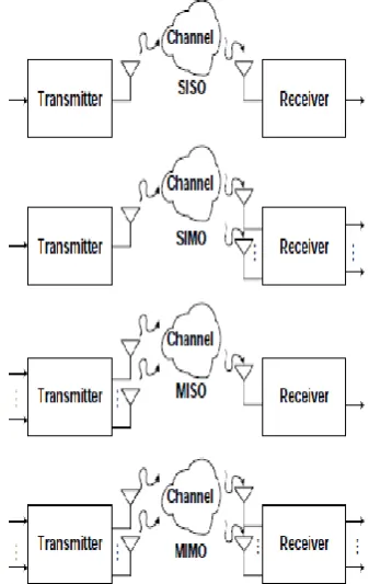
The different forms of antenna technology refer to different levels of inputs and outputs. These are related to the radio link. The different forms of single / multiple antenna links are defined as below and also shown in figure 3:
SISO - Single Input Single Output
SIMO - Single Input Multiple output
MISO - Multiple Input Single Output
MIMO - Multiple Input multiple Output
Available online: http://edupediapublications.org/journals/index.php/IJR/ P a g e | 292
interference. As the requirements on data rate and quality of service for wireless communications systems are increased, call for new techniques became necessary in order to increase spectrum efficiency and to improve link reliability. The use of multiple antennas at both the ends of a wireless link promises significant improvements in terms of spectral efficiency and link reliability. This technology is known as multiple-input multiple-output.
Figure 3: SISO and MIMO models
When there is more than one antenna at either end of the radio link, then it is termed as MIMO - Multiple Input Multiple Output. MIMO can be used to provide improvements in both channel robustness as well as channel throughput. To get benefited from MIMO completely it is necessary to utilise coding on the channels to separate the data from the
different paths. This requires processing, but provides additional channel robustness / data throughput capacity.
There are different formats of MIMO that can be used from SISO, through SIMO and MISO to the full MIMO systems. These are all able to provide significant improvements of performance, but at the cost of additional processing, the number of antennas used will be increased. Balancing the performance against costs, size, processing available the battery life also must be saved.
IV. MIMO STC AND SPATIAL MULTIPLEXING
To take advantage of the additional throughput capability, MIMO utilises several sets of antennas. In many of the MIMO systems only two transmitting and receiving antennas are used, as we further employ antennas it increases the throughput but there is great complexity. In any case for MIMO spatial multiplexing the number of receiver side antennas must be greater than or equal to the number of transmitting side antennas.
Initially after coding as per the Space Time code (STC), we multiply the symbols with the channel and then add white Gaussian noise to it, and then equalize the received symbols. Perform hard decision decoding and count the bit errors. Finally, repeat for multiple values
of and plot the simulation and theoretical results.
Available online: http://edupediapublications.org/journals/index.php/IJR/ P a g e | 293
transmitted from antennas 1, 2,…..n. Then there can be variety of paths that are used with each path having different channel properties. The receiver must be able to differentiate between the different data streams which are necessary to be used for further processing. These can be represented by the properties h12, travelling from transmit antenna one to receive antenna 2 and so forth. In this way for a three transmit, three receive antenna system a matrix can be set up:
r
1 =h
11t
1 +h
21 t2 +h
31t
3r
2 =h
12t
1 +h
22 t2 +h
32t
3r
3 =h
13t
1 +h
23 t2 +h
33t
3Where r1 = signal received at antenna 1, r2 is the signal received at antenna 2 and so forth.
In matrix format this can be represented as:
[R] = [H] x [T]
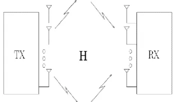
The basic MIMO Antenna System is shown in the figure 4. To recover the transmitted data-stream at the receiver it is necessary to perform a considerable amount of signal processing. First the MIMO system decoder must estimate the individual channel transfer characteristic
h
ij to determine the channel transfermatrix. Once all of this has been estimated, then the matrix [H] has been produced and the transmitted data streams can be reconstructed by multiplying the received vector with the inverse of the transfer matrix.
[T] = [H]-1 x [R]
This process can be the effective method for solving of a set of N linear simultaneous equations to reveal the values of N variables.
In reality the situation is a little more difficult than this, as propagation is never quite straightforward, and in addition to this each variable consists of an ongoing data stream, this nevertheless demonstrates the basic principle behind MIMO wireless systems.
Figure 4: Basic MIMO Antenna System
IV.I CHANNEL CAPACITY
A fundamental theory of communication channel capacity (C) was first proposed by Claude Shannon for additive white Gaussian channels in 1948. This theorem stipulates that the maximum error-free data rate that a channel can convey is given by-
C = log2(1 + ρ) (bps/Hz)
Where ρ is the SNR. Since then the
Shannon bound represents the upper limit
Available online: http://edupediapublications.org/journals/index.php/IJR/ P a g e | 294 C = {log2(1 + ρ|h|2)} (bps/Hz)
V. SIMULATION RESULTS:
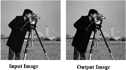
Here in this project, image is applied as input in order to view the result physically. The input and output images are shown in the figure 5.
Figure 5: Input and Output Images
The scattering plots of QAM OFDM are shown in the figure 6. From the figure we can observe that in the receiver side scattering plot there is no interference of points which means that the interference is almost nullified, which shows the efficiency of the designed system. Figure 7 shows the scattering plot with AWGN noise with S/N ratio 30dB.
Figure 6: Scattering plots at transmitting and receiving sides without noise
Figure 7: Scattering plot with AWGN noise after STC at receiver side.
Figure 8: MIMO Capacity comparison in different links
Figure 9: Bit Error Rate of QAM in AWGN channel with 2 transmitters
Available online: http://edupediapublications.org/journals/index.php/IJR/ P a g e | 295
receivers and graph is plotted which is shown in figure 8. In figure 9 the bit error rate of QAM in AWGN fading channel with two transmitters is calculated and
plotted with respect to .
VI. CONCLUSION:
From the performance, with different antenna configurations and propagation conditions the proposed MIMO-OFDM (STC) gives potentially higher spectral efficiency. Initially after coding as per the Space Time code (STC), we multiply the symbols with the channel and then add white Gaussian noise to it, and then equalize the received symbols. Perform hard decision decoding and count the bit errors. Finally by repeating the same for
multiple values of we obtain the plot for simulation and theoretical results. The code for simulation is done in MATLAB This design can provides high data rate and high performance over wireless channels that may be time selective and frequency-selective and satisfies our requirement to enhance the high data rates. The spectral efficiency can be improved using above design by reducing cross talks.
REFERNCES:
[1] R.W Chang, “Orthogonal Frequency Division Multiplexing,” U.S Patent
3388455, Jan 6, 1970, Filed Nov.4.1966.
[2] Ramjee Prasad, “OFDM for Wireless Communications systems”, Artech House Publishers, 2004.
[3] B. Hirosaki, “An Analysis of Automatic Equalizers for Orthogonally
Multiplexed QAM Systems,” IEEE
Transaction Communication, Vol.28,
pp.73-83, Jan.1980.
[4] E. Biglieri, J. Proakis, and S.Shamai(Shitz), “Fading channels: Information-Theoretic & communications Aspects,” IEEE Trans. on Information
Theory, vol. 44, no. 6, pp. 2619–2692, Oct.
1998.