ISSN (Print) : 2320 – 3765 ISSN (Online): 2278 – 8875
I
nternational
J
ournal of
A
dvanced
R
esearch in
E
lectrical,
E
lectronics and
I
nstrumentation
E
ngineering
(A High Impact Factor, Monthly, Peer Reviewed Journal) Website: www.ijareeie.com
Vol. 7, Issue 5, May 2018
Simulation & Performence Analysis Of
Multiple Wind Turbine with ESS
Poonam Rani1, Dr. Pratibha Tiwari2
UG Student, Dept. of EE, SHUATS, Allahabad, UP, India1 Assistant Professor, Dept. of EE, SHUATS, Allahabad, UP, India2
ABSTRACT:Wind turbine generators (WTGs) are usually controlled to generate maximum electrical power from wind under normal wind conditions. With the increasing penetration of wind power into electric power grids, energy storage devices will be required to dynamically match the intermittency of wind energy.
This paper presents the performance analysis of two-layer constant-power control (CPC) scheme for a wind farm equipped with doubly fed induction generator (DFIG) wind turbines, where each WTG is equipped with a super capacitor energy storage system (ESS). To meet the requirements of frequency and active power regulation, energy storage devices will be required to dynamically match the intermittency of wind energy. In the two layer control, there is a high layer controller known as Wind farm supervisory control (WFSC), which generates Active power (P), Stator power (Ps), Energy storage power (Pe), DC voltage (Vdc) etc. references for the low layer Wind turbine generator (WTG) controllers, according to the power demand from the grid operator. The low layer wind turbine generator(WTG) controller consist of Rotor side converter control and Grid side converter control to regulate each Double fed induction generator (DFIG) wind turbine, to generate desired amount of active power, Where the deviations between the available wind energy input and desired active power output are compensated by Super capacitor Energy storage system. Simulation are carried out in MATLAB on a wind farm equipped with multiple DFIG wind turbines to verify the effectiveness of the proposed control scheme.
KEYWORDS:Constant power control (CPC), Super-capacitor Energy storage system, Wind farm supervisory control, Wind Turbine Generator Contollers, doubly fed induction generator (DFIG).
I.INTRODUCTION
Wind turbine generators (WTGs) are usually controlled to generate maximum electrical power from wind under normal wind conditions. However, because of the variations of wind speed, the generated electrical power of a WTG is usually fluctuated. Currently, wind energy provides about 1%–2% of the world‘s electricity supply. At such a penetration level, it is not necessary to require WTGs to participate in automatic generation control, unit commitment, or frequency regulation. However, it is reasonable to expect that wind power will be capable of becoming a major contributor to the nation’s and world’s electricity supply over the next three decades.
ISSN (Print) : 2320 – 3765 ISSN (Online): 2278 – 8875
I
nternational
J
ournal of
A
dvanced
R
esearch in
E
lectrical,
E
lectronics and
I
nstrumentation
E
ngineering
(A High Impact Factor, Monthly, Peer Reviewed Journal) Website: www.ijareeie.com
Vol. 7, Issue 5, May 2018
This paper proposes a novel two-layer constant power control (CPC) scheme for a wind farm equipped with doubly fed induction generator (DFIG) wind turbines [14], where each WTG is equipped with a super-capacitor energy storage system (ESS).
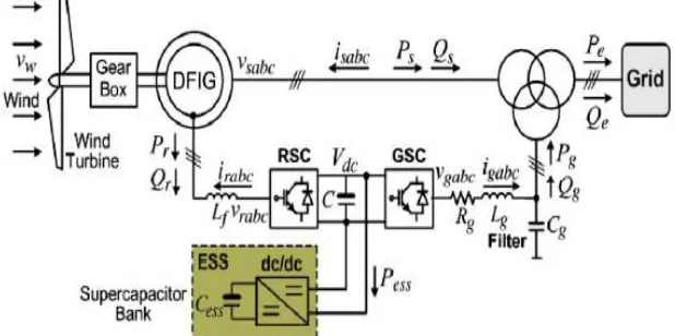
Fig. 1. Configuration of a DFIG wind turbine equipped with a supercapacitor ESS connected to a power grid.
The CPC consists of a high-layer wind farm supervisory controller (WFSC) and low-layer WTG controllers. The high layer WFSC generates the active power references for the low layer WTG controllers of each DFIG wind turbine according to the active power demand from the grid operator. The low-layer WTG controllers then regulate each DFIG wind turbine to generate the desired amount of active power, where the deviations between the available wind energy input and desired active power output are compensated by the ESS. Simulation studies are carried out in MATLAB for a wind farm equipped with multiple DFIG wind turbines to verify the effectiveness of the proposed control scheme.
II. MODELLING OF WIND TURBINE
The mechanical power of the turbine is given by:
Pm = ½ Au3cp (1)
where Pm is the power extracted from the airflow, ρ is the air density, A is the area covered by the rotor, u is the wind speed upstream of the rotor, and cpis the performance coefficient or power coefficient.
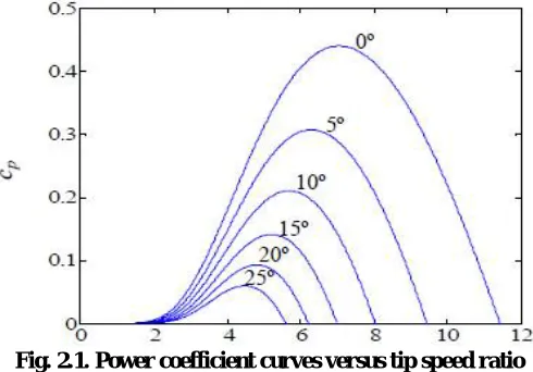
The power coefficient is a function of the pitch angle of rotor blades θ and of the tip speed ratio λ, which is the ratio between blade tip speed and wind speed upstream of the rotor.
The computation of the power coefficient requires the use of blade element theory and the knowledge of blade geometry. We consider the blade geometry using the numerical approximation developed in [7], assuming that the power coefficient is given by:
Cp= 0.73λi 18.4/λii (2)
where λiand λiiare respectively given by:
λi= 151/ λii – 0.58θ – 0.002 θ2.14 -13.2 (3)
λii= 1/ [ 1/( λ – 0.02θ) – 0.003/(θ3+1)] (4)
The maximum power coefficient is given for a null pitch angle and is equal to:
ISSN (Print) : 2320 – 3765 ISSN (Online): 2278 – 8875
I
nternational
J
ournal of
A
dvanced
R
esearch in
E
lectrical,
E
lectronics and
I
nstrumentation
E
ngineering
(A High Impact Factor, Monthly, Peer Reviewed Journal) Website: www.ijareeie.com
Vol. 7, Issue 5, May 2018
where the optimum tip speed ratio is equal to:
λopt = 7.057 (6)
The power coefficient is illustrated in Figure 2.1 as a function of the tip speed ratio.
Fig. 2.1. Power coefficient curves versus tip speed ratio
The mechanical power extracted from the wind is modelled by (1) to (4). The equations for modelling rotor motion are given by:
= 1/Jm (Tm –Tdm – Tam- Telas) (7)
= 1/Je (Telas –Tde – Tae- Te) (8)
Where ωmis the rotor speed of turbine, Jmis turbine moment of inertia, Tmis the mechanical torque, Tdmis the resistant
torque in the turbine bearing, Tamis the resistant torque in the hub and blades due to the viscosity of the airflow, Telasis
the torque of the torsional stiffness, ωeis the rotor speed of the electric machine, Je is the electric machine moment of
inertia, Tdeis the resistant torque in electric machine bearing, Taeis the resistant torque due to the viscosity of the airflow
in the electric machine, and Te is the electric torque. The equations for modelling a permanent magnetic synchronous machine, PMSM, can be found in diverse literature; using the motor machine convention, the following set of equations is considered:
= 1/Ld (ud – pωeLqiq – Rdid) (9)
= 1/Lq (uq – pωe (Lqiq + Mif) – Rqiq) (10)
where ifis the equivalent rotor current, M is the mutual inductance, p is the number of pairs of poles; and where in d q
axes id and iq are the stator currents, Ld and Lq are the stator inductances, Rd and Rq are the stator resistances, ud and uq are the stator voltages. A unity power factor is imposed to the electric machine, implying a null Qe . The electric power Pe is given by:
Pe = [ ud uq uf] [id iq if ]T (11)
ISSN (Print) : 2320 – 3765 ISSN (Online): 2278 – 8875
I
nternational
J
ournal of
A
dvanced
R
esearch in
E
lectrical,
E
lectronics and
I
nstrumentation
E
ngineering
(A High Impact Factor, Monthly, Peer Reviewed Journal) Website: www.ijareeie.com
Vol. 7, Issue 5, May 2018
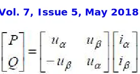
where in α β axes, iαand iβare the phase currents, uαand uβare the phase voltages. The apparent output power is given
by:
S = ( P2 + Q2 + H2)1/2 (12) where H is the harmonic power.
III.DFIG WIND TURBINE WITH ENERGY STORAGE SYSTEM
Fig. 3.1 shows the basic configuration of a DFIG wind turbine equipped with a supercapacitor-based ESS. The low-speed wind turbine drives a high-low-speed DFIG through a gearbox. The DFIG is a wound-rotor induction machine. It is connected to the power grid at both stator and rotor terminals. The stator is directly connected to the grid, while the rotor is fed through a variable-frequency converter, which consists of a rotor-side converter (RSC) and a grid-side converter (GSC) connected back to back through a dc link and usually has a rating of a fraction (25%–30%) of the DFIG nominal power. As a consequence, the WTG can operate with the rotational speed in a range of ±25%–30% around the synchronous speed, and itsactive and reactive powers can be controlled independently.
In this paper, an ESS consisting of a supercapacitor bank and a two-quadrant dc/dc converter is connected to the dc link of the DFIG converters. The ESS serves as either a source or a sink of active power and therefore contributes to control the generated active power of the WTG. The value of the capacitance of the supercapacitor bank can be determined by
Cess = 2PnT / V2SC (13)
where Cess is in farads, Pn is the rated power of the DFIG in watts, VSC is the rated voltage of the supercapacitor bank in volts, and T is the desired time period in seconds that the ESS can supply/store energy at the rated power (Pn) of the DFIG. The use of an ESS in each WTG rather than a large single central ESS for the entire wind farm is based on two reasons.
ISSN (Print) : 2320 – 3765 ISSN (Online): 2278 – 8875
I
nternational
J
ournal of
A
dvanced
R
esearch in
E
lectrical,
E
lectronics and
I
nstrumentation
E
ngineering
(A High Impact Factor, Monthly, Peer Reviewed Journal) Website: www.ijareeie.com
Vol. 7, Issue 5, May 2018
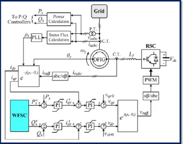
Fig. 3.1. Overall vector control scheme of the RSC
IV.CONTROL OF INDIVIDUAL DFIG WIND TURBINE
The control system of each individual DFIG wind turbine generally consists of two parts: 1) the electrical control of the DFIG and 2) the mechanical control of the wind turbine blade pitch angle and yaw system. Control of the DFIG is achieved by controlling the RSC, the GSC, and the ESS (see Fig. 1). The control objective of the RSC is to regulate the stator-side active power Ps and reactive power Qs independently. The control objective of the GSC is to maintain the dc-link voltage Vdc constant and to regulate the reactive power Qg that the GSC exchanges with the grid. The control objective of the ESS is to regulate the active power Pg that the GSC exchanges with the grid. In this paper, the mechanical control of the wind turbine blade pitch angle is similar to that in [7].
V.SIMULATION & RESULTS
Simulation studies are carried out for a wind farm with 15 DFIG wind turbines (see Fig. 5.1) to verify the effectiveness of the proposed control scheme under various operating conditions.
ISSN (Print) : 2320 – 3765 ISSN (Online): 2278 – 8875
I
nternational
J
ournal of
A
dvanced
R
esearch in
E
lectrical,
E
lectronics and
I
nstrumentation
E
ngineering
(A High Impact Factor, Monthly, Peer Reviewed Journal) Website: www.ijareeie.com
Vol. 7, Issue 5, May 2018
Figure 5.1: Simulink model of DFIG wind turbine with energy storage system
A. CPC During Variable Wind Speed Conditions
ISSN (Print) : 2320 – 3765 ISSN (Online): 2278 – 8875
I
nternational
J
ournal of
A
dvanced
R
esearch in
E
lectrical,
E
lectronics and
I
nstrumentation
E
ngineering
(A High Impact Factor, Monthly, Peer Reviewed Journal) Website: www.ijareeie.com
Vol. 7, Issue 5, May 2018
Figure 5.2: Wind Speed of Wind Turbines
ISSN (Print) : 2320 – 3765 ISSN (Online): 2278 – 8875
I
nternational
J
ournal of
A
dvanced
R
esearch in
E
lectrical,
E
lectronics and
I
nstrumentation
E
ngineering
(A High Impact Factor, Monthly, Peer Reviewed Journal) Website: www.ijareeie.com
Vol. 7, Issue 5, May 2018
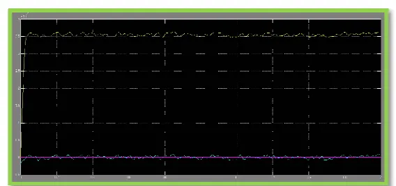
Figure 5.4: Output of active power and power generated by wind turbine W1
Figure 5.5: Output of active power and power generated by wind turbine W2
Figure 5.6: Output of active power and power generated by wind turbine W3
VI.CONCLUSION
ISSN (Print) : 2320 – 3765 ISSN (Online): 2278 – 8875
I
nternational
J
ournal of
A
dvanced
R
esearch in
E
lectrical,
E
lectronics and
I
nstrumentation
E
ngineering
(A High Impact Factor, Monthly, Peer Reviewed Journal) Website: www.ijareeie.com
Vol. 7, Issue 5, May 2018
controllers, which are coordinated by a high-layer WFSC to generate constant active power as required by or committed to the grid operator.
Simulation studies have been carried out for a wind farm equipped with 15 DFIG wind turbines to verify the effectiveness of the proposed CPC scheme. Results have shown that the proposed CPC scheme enabled the wind farm to effectively participate in unit commitment and active power and frequency regulations of the grid. The proposed system and control scheme provides a solution to help achieve high levels of penetration of wind power into electric power grids.
REFERENCES
[1]. Liyan Qu, Wei Qiao,“ Constant Power Control of DFIG Wind Turbines With Supercapacitor Energy Storage”, IEEE TRANSACTIONS ON INDUSTRY APPLICATION, volume:47 Issue:1 ©2011 IEEE.
[2]. Marwa Ezzat, Mohamed Benbouzid, S.M. Muyeen and Lennart Harnefors, “Low-Voltage Ride- Through Techniques for DFIG-Based Wind Turbines:State-of-the-Art Review and Future Trends’’,IEEE Harnefors is with ABB, Corporate Research Västerås, Sweden.
[3]. Zaijun Wu , Chanxia Zhu and Minqiang Hu “Improved Control Strategy for DFIG Wind Turbines for Low Voltage Ride Through’’, Energies 2013, 6,1181-1197; doi: 10.3390/en6031181, 25 February 2013.
[4]. Mr. Subir Datta, Mr. Ksh. Robert Singh, Mr. Subhasish Deb, “Enhancement of Fault Ride through Capability of Doubly Fed Induction Generator Based Wind Energy Conversion System”, International Journal of Advanced Information Science and Technology (IJAIST) ISSN: 2319:2682 Vol.28, No.28, August 2014.
[5]. W. Qiao and R. G. Harley, “Grid connection requirements and solutions for DFIG wind turbines,” in Proc. IEEE Energy Conf., Atlanta, GA, Nov. 17–18, 2008, pp. 1–8.
[6]. R. Piwko, D. Osborn, R. Gramlich, G. Jordan, D. Hawkins, and K. Porter, “Wind energy delivery issues: Transmission planning and competitive electricity market operation,” IEEE Power Energy Mag., vol. 3, no. 6, pp. 47–56, Nov./Dec. 2005.
[7]. L. Landberg, G. Giebel, H. A. Nielsen, T. Nielsen, and H. Madsen, “Shortterm prediction—An overview,” Wind Energy, vol. 6, no. 3, pp. 273– 280, Jul./Sep. 2003.
[8]. M. Milligan, B. Kirby, R. Gramlich, and M. Goggin, Impact of Electric Industry Structure on High Wind Peneration Potential, Nat. Renewable Energy Lab., Golden, CO, Tech. Rep. NREL/TP-550-46273. [Online].
[9]. J. P. Barton and D. G. Infield, “Energy storage and its use with intermittent renewable energy,” IEEE Trans. Energy Convers., vol. 19, no. 2, pp. 441– 448, Jun. 2004.
[10]. D. Rastler, “Electric energy storage, an essential asset to the electric enterprise: Barriers and RD&D needs,” California Energy Commission Staff Workshop Energy Storage Technol., Policies Needed Support California’s RPS Goals 2020, Sacramento, CA, Apr. 2, 2009.
[11]. C. Abbey and G. Joos, “Supercapacitor energy storage for wind energy applications,” IEEE Trans. Ind. Appl., vol. 43, no. 3, pp. 769–776, May/Jun. 2007.
[12]. M. Milligan, B. Kirby, R. Gramlich, and M. Goggin, Impact of Electric Industry Structure on High Wind Peneration Potential, Nat. Renewable Energy Lab., Golden, CO, Tech. Rep. NREL/TP-550-46273. [Online].
[13]. J. P. Barton and D. G. Infield, “Energy storage and its use with intermittent renewable energy,” IEEE Trans. Energy Convers., vol. 19, no. 2, pp. 441– 448, Jun. 2004.
[14]. D. Rastler, “Electric energy storage, an essential asset to the electric enterprise: Barriers and RD&D needs,” California Energy Commission Staff Workshop Energy Storage Technol., Policies Needed Support California’s RPS Goals 2020, Sacramento, CA, Apr. 2, 2009.
BIOGRAPHY
Dr. Pratibha Tiwari presently working as Assistant Professor in Electrical Engineeringat Sam Higginbottom Institute of Agriculture Technology & Sciences, Allahabad, (U.P) India. The degree of B.Tech secured in Electrical & Electronics Eng. from UCER, Allahabad in 2002 and M.Tech. in Control and Instrumentation from MNNIT, Allahabad in 2006. Research interest includes Control & Instr. and Power Electronics.