Proximity Fed Series Triangular Patch
Microstrip Antenna
Dinesh B. Ganure1, S. L. Mallikarjun2, P. M. Hadalgi3, P. V. Hunagund4
Research Scholar, Department of Applied Electronics, Gulbarga University, Kalaburagi, Karnataka, India1
Guest Faculty, Department of Applied Electronics, Gulbarga University, Kalaburagi , Karnataka, India2
Professor, Department of Applied Electronics, Gulbarga University, Kalaburagi, Karnataka, India3
Professor, Department of Applied Electronics, Gulbarga University, Kalaburagi, Karnataka, India4
ABSTRACT: In this paper a design of proximity fed series triangular patch microstrip antenna is proposed. The fabricated antenna uses two-layer substrates with the microstrip-line on the lower layer and the patch antenna on upper layer such as the feed line terminates in an open end underneath the patch. In this study a series of four triangular patches as a radiating element is used in order to increase the impedance bandwidth showing quad band operation. The other antenna parameters such as Radiation pattern, return loss, VSWR and HPBW is calculated and discussed. The proposed antenna finds the application in modern wireless communication systems.
KEYWORDS: Microstrip antenna, proximity feed, quad band, gain and VSWR.
I. INTRODUCTION
In the present-time communication, antennas cover a wide range of applications in different areas, such as mobile communication, satellite navigation, internet services, automobiles and radars. Especially they are applied to microstrip antennas, because of its characteristics like low profile, lightweight and low power handling capacity [1-4]. However, gain and bandwidth are sometimes low and not sufficient in most of applications. Modification of shape and using special materials could be useful to solve such backlashes of this type of antennas.
Therefore it becomes very important to develop a technique to increase the bandwidth and gain of the microstrip antenna. In some applications where the increased bandwidth is needed, dual, triple or quad frequency band antenna is one of the alternative solutions. When modern communication system, such as satellite, Wi-Max and radar requires operation at two frequencies, dual frequency patch antennas may avoid the use of two separate antennas [5, 6]. Similarly various studies on slots have seen in the literature in order to achieve two or more than two band operations were reported. Design of quad band operation of antenna at four different bands of frequencies which is possible by constructing two rhombus slots on rectangular microstrip patch element [7]. A new quad-band small size microstrip handset antenna is designed using different substrate material [8]. A single feed dual layer rectangular microstrip antenna with single short pin which gives quad-band antenna can operate effectively in four frequency bands [9].
The present study is made by fabricating a series of triangular patch antenna using proximity feeding method. It uses a two –layer substrate with the microstrip line on the lower layer and the patch antenna on the upper layer. The feed line terminates in an open end underneath the patch [10, 11]. Basically a series of four triangle shaped patch is extracted from a rectangular patch antenna. An optimum triangular patches of dimension a = 18 mm, b = 18 mm and c = 24 mm has been inserted on the radiating element of the patch.
II. ANTENNA DESIGN
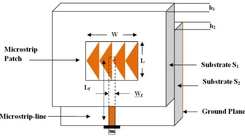
Figure 1 shows the top view geometry of antenna. It consists of a series of four triangular patches etched on top surface of substrate S1. The microstripline feed of length Lf = 24.971 cm and width Wf = 3.166 cm is etched on the top surface
of substrate S2. The substrate S2 is placed below substrate S1 and the bottom surface of the substrate S2 acts as the
ground plane.
Fig. 1 Geometry of proposed antenna
The proposed has been designed for 3 GHz. The art work of the proposed antenna is sketched by using computer software Auto-CAD 2006 to achieve better accuracy and the substrate material of thickness ofh= 1.66 mm is same for both layers. At the tip of microstrip feed line, a 50 Ω coaxial SMA connector is connected for feeding the microwave
power.
III. EXPERIMENTAL RESULTS
The measurements are taken on Vector Network Analyzer (Rohde & Schwarz, German make ZVK Model No. 1127.8651). The impedance bandwidth over return loss less than -10dB for the proposed antenna is measured which is shown in Figure 2. The experimental impedance bandwidth is defined as,
Impedance Bandwidth (%) =
× 100
... (1)From the figure it is observed that, antenna operates for quad band of frequencies at 2.94 GHz, 3.39 GHz, 4.81 GHz and 7.21 GHz. The experimental impedance bandwidth (BW1) at 2.94 GHz is found to be 105 MHz (3.58%), at 3.39
GHz the impedance bandwidth (BW2) is 35 MHz (1.03%), at 4.81 GHz the impedance bandwidth (BW3) is 157.5 MHz
(3.26%) and the impedance bandwidth (BW4) at 7.21 GHz is 122.5 MHz (1.69%). Similarly the minimum return loss
measured in this antenna is found to be -13.22 dB, -14.80 dB, -14.54 dB and -11.73 dB respectively.
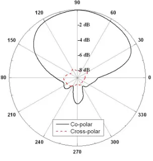
The X-Y plane co-polar and cross-polar radiation patterns of antenna are measured at their resonating frequencies and the radiation pattern at 3.39 GHz is shown in Figures 3. The figure indicates that the antenna shows broader side radiation characteristics. The cross-polarization level of this antenna is found to be below -8dB.
Fig. 3: Radiation pattern at 3.39 GHz
The half power beam width (HPBW) and gain for the proposed antenna are calculated for the resonating frequency at 2.94 GHz and are shown in Table 1. The gain of proposed antenna is calculated using absolute gain method given by the equation, [6]
( ) = − ( ) − …….. (2)
where, Pt and Pr are transmitted and received powers respectively, Gt is the gain of the pyramidal horn antenna and R is the distance between transmitting antenna and antenna under test. The gain of the antenna is tabulated in Table 1
.
Similarly, Voltage Standing Wave Ratio (VSWR) is found to be 1.582 and this corresponds to a perfect match [12] which is shown in Figure 4.Table 1: Calculated Gain, HPBW and VSWR
Substrate Height
Freq. in GHz
Gain in dB
HPBW in degrees
VSWR
S1=1.6mm
S2=1.6mm 3.39 5.02 140
0
Fig. 4: VSWR
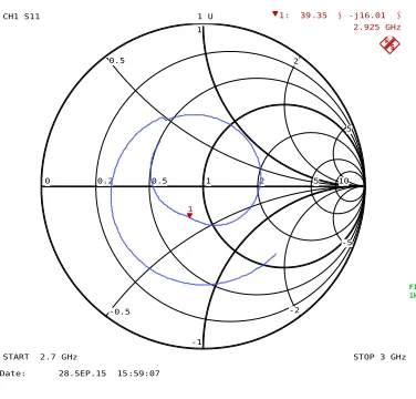
Figure 5 shows the Smith chart of the proposed antenna and the impedance matching is found at 39.35 - j16.010 which illustrates the nearly matching of the feedline and radiating patch at 50Ω to the standard value [6].
Fig. 5: Smith chart profile
IV. CONCLUSION
The experimental study illustrates that the antenna is relatively simple in design and fabrication and quite good in enhancing the bandwidth by quad frequency operation and gives broadside radiation pattern. The other antenna parameter return loss, gain and VSWR are found to be good. This antenna is better as it uses low cost substrate material and finds applications in S and C-band frequency ranges such as in modern wireless communication systems.
ACKNOWLEDGEMENTS
0 0.2 0.5 1 2 5 10
-5
-2
-1 -0.5 0.5
1
2
5
CH1 1 U
START 2.7 GHz STOP 3 GHz
FIL 1k 1k FIL 1k 1k S11
1
1: 39.35 -j16.01
2.925 GHz
[3] Girish Kumar and K. P. Ray, Broadband Microstrip Antennas, Norwood, MA: Artech House, 2003. [4] David M. Pozar, Microwave Engineering, Addison Wesley Publishing Company, Inc. 1990.
[5] S. Maci and G. B. Gentili, “Dual Frequency Patch Antennas”, IEEE Antennas and Propogation Magazine, Vol.39, No.6, December 1997. [6] S. L. Mallikarjun and P. M. Hadalgi, “Single layer modified rectangular microstrip array antenna for multi band and wide band applications”,
Indian Journal of Radio Physics, Vol.39, pp.156-162, 2010.
[7] Ambresh P. A., A. A. Sujata, A. M. Khan, P. M. Hadalgi, and P. V. Hunagund, “Quad Band Rectangular Microstrip Antenna for S and C-Band Applications”, International Journal of Computer and Communication Engineering, Vol. 3, No. 5, pp.334-337, September 2014.
[8] Asem S. Al-Zoubi, Mohamed A. Moharram, “Quad-Band Microstrip Antenna for Mobile Handsets”, Journal of Theoretical and Applied Information Technology, Vol. 60 No.1 pp. 106-111, February 2014.
[9] Gada Mahamood Faisal, Kaydar Majeed Quboa and Dia Mohamad Ali, “Quad band dual layer microstrip antenna design for mobile handset”, American Journal of Electrical and Electronics Engineering, Vol. 2, No. 2, pp. 51-56, 2014.
[10] B. G. Dinesh, S. L. Mallikarjun, G. M. Pushpanjali and P. M. Hadalgi, “Diagonal slot-loaded rectangular microstrip patch antenna”, Indian Journal of Scientific Research, Vol.12, Special Issue No. 1, pp.214-216, 2015.