Available online:
https://edupediapublications.org/journals/index.php/IJR/
P a g e | 20071 K.Srin iv as Red d y , 2 K.Harith a
1M.Tech student, Dept. of ECE, Sphoorthy Engineering College,Hyderabad,Telangana, India
2 Assistant Professor Dept. of ECE, Sphoorthy Engineering College,Hyderabad,Telangana, India
ABSTRACT:
This paper presents the
least-mean-square (LMS) adaptive filter for deriving its
Architectures for high-speed and low
complexity implementation. Among many
adaptive algorithms that exist in the open
literature, the class of approaches which are
derived from the minimization of the mean
squared error between the output of the
adaptive filter and some desired signal seems
to be the most popular. A novel partial product
generator has been used for achieving lower
adaptation
delay and area-delay-power
efficient implementation. The relationship
between the step size and the convergence
speed, and the effect of the delay on the
convergence speed are also studied. The
analytical results are supported by the
computer simulations. The problem of the
efficient realization of a DLMS transversal
adaptive filter is investigated.
KEYWORDS-
Adaptive Filters, Critical-Path
Optimization, Least Mean Square Algorithms,
LMS Adaptive Filter.
I. INTRODUCTION
The Least Mean Square (LMS) adaptive filter is the widely used filter because of its simplicity and
performance. Least mean squares (LMS)
algorithms are a class of adaptive filter used to mimic a desired filter by finding the filter coefficients that relate to producing the least mean squares of the error signal (difference between the desired and the actual signal). It is stochastic gradient method in that the filter is only adapted based on the error at the current time. The LMS algorithm is the most popular method for adapting a filter, which have made it widely adopted in many applications. Applications include adaptive channel equalization, adaptive predictive speech
coding, Noise Suppression and on-line system identification. Recently, because of the progress of digital signal processors, a variety of selective coefficient update of gradient-based adaptive algorithms could be implemented in practice. The Least Mean Square adaptive filter is used here because it differs from a traditional digital filter in the following ways: A traditional digital filter has only one input signal x(n) and one output signal y(n). An adaptive filter requires an additional input signal d(n) and returns an additional output signal e(n). The filter coefficients of a traditional digital filter do not change over time. The coefficients of an adaptive filter change over time. Therefore, adaptive filters have a self-learning ability that traditional digital filters do not have. The filter is an important component in the communication world. It can eliminate unwanted signals from useful information. However, to obtain an optimal filtering performance, it requires ‘a priori’ knowledge of both the signal and its embedded noise statistical information. The classical approach to this problem is to design frequency selective filters, which approximate the frequency band of the signal of interest and reject those signals outside this frequency band.
II. RELA TED W ORKS
This algorithm is a class of adaptive filter used to mimic a desired filter by finding the filter coefficients that relate to producing the least mean squares of the error signal [1]. The LMS algorithm was devised for the study of a patternrecognition machine known as the adaptive linear element. The LMS algorithm is a stochastic gradient algorithm in that it iterates each tap weight of the transversal filter in the direction of the instantaneous gradient of the squared error signal with respect to the tap weights [2]. The existing systolic architectures for the LMS algorithm with delayed coefficient adaptation have large adaptation delay and hence degraded convergence behaviour. The proposed
Analysis of Low Power, Area Efficient LMS Adaptive Filter with
Available online:
https://edupediapublications.org/journals/index.php/IJR/
P a g e | 2008system gives the systolic architecture with minimal
adaptation delay and input/output latency, thereby improving the convergence behaviour to near that of the original LMS algorithm. [3]. An efficient systolic architecture for the DLMS adaptive filter is based on a new tree-systolic processing element (PE) and an optimized tree-level rule. Applying tree-systolic, a higher convergence rate than that of the conventional DLMS structures can be obtained without the properties of the systolic-array architecture [4]. The DLMS adaptive algorithm is introduced to achieve lower adaptation-delay. It can be implemented using pipelining. But it can be used only for large order adaptive filters [5]. Typical DSP Programs with highly real-time, design hardware and or software to meet the application speed constraint. It also deals with 3-Dimensional Optimization (Area, Speed, and Power) to achieve required speed, area-power tradeoffs and power consumption [6]. An efficient scheme is presented for implementing the LMS-based transversal adaptive filter in block floating-point (BFP) format, which permits processing of data over a wide dynamic range, at temporal and hardware complexities significantly less than that
of a floating-point processor [7]. The
implementation of adaptive filters with fixed-point arithmetic requires to evaluate the computation quality. The accuracy may be determined by calculating the global quantization noise power in the system output [8]. The LMS algorithm is the most popular method for adapting a filter, which is used in many applications such as adaptive channel equalization, adaptive predictive speech coding,
Noise Suppression and online system
identification.
For every input sample, the LMS algorithm calculates the filter output and finds the difference between the computed output and the desired response. Using this difference the filter weights are updated in every cycle. During the n-th iteration, LMS algorithm updates the weights as follows:
Wn+1 = wn + μ · e(n) · x(n)……….. (1a) Where,
e(n) = d(n) − y(n) y(n) = wTn· x(n) (1b) Here,
x(n) is the input vector
w(n) is the weight vector of an Nth order LMS adaptive filter at the nth iteration, respectively, given by, x(n) = [x(n), x(n − 1), · · ·, x(n − N + 1)]T
wn = [wn(0), wn(1), · · ·, wn(N − 1)]T
d(n) is the desired response and y(n) is the filter output of the nth iteration.
e(n) denotes the error computed in the nth iteration which is used to update the weights. μ is the convergence-factor. The DLMS algorithm, instead of using the recent-most feedback-error e(n) corresponding to the n-th iteration for updating the filter weights, it uses the delayed error e(n−m), (i.e.) the error corresponding to (n−m)-th iteration for updating the current weight. The weight-update equation of DLMS algorithm is given by,
Wn+1 = wn + μ · e(n − m) · x(n − m) ……… (2)
where, m is the adaptation-delay.
III. SYSTEM DESIGN OF A DA PTIVE
FILTER
Available online:
https://edupediapublications.org/journals/index.php/IJR/
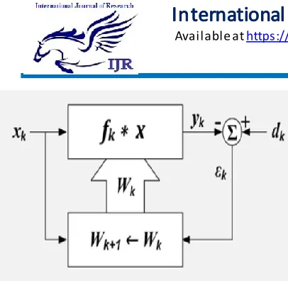
P a g e | 2009Fig. 1. Structure of a basic Adaptive filter
As the power of digital signal processors has increased, adaptive filters have become much more common and are now routinely used in devices such as mobile phones and other communication devices, camcorders and digital cameras, and medical monitoring equipment.
The problem of efficiently realizing a delayed leastmean-squares (DLMS) transversal adaptive filter is investigated. A time-shifted version of the DLMS algorithm is derived. Due to its order recursive nature, the restructured algorithm is well suited to parallel implementation. The performance of the pipelined system is analyzed, and equations for speedup are derived. The pipelined system is capable of much greater throughput than existing
conventional least-mean-square (LMS)
implementations, making it a good candidate for real-time applications where high sampling rates are required. Also, due to its high modular nature, the system is easily expandable. The behaviour of the delayed least-mean-square (DLMS) algorithm is studied. It is found that the step size in the coefficient update plays a key role in the convergence and stability of the algorithm. An upper bound for the step size is derived that ensures the stability of the DLMS. The relationship between the step size and the convergence speed, and the effect of the delay on the convergence speed, are also studied. The analytical results are supported by computer simulations.
The proposed design is found to be more efficient in terms of the power-delay product (PDP) and energy-delay product (EDP) compared to the existing structures. The block diagram of the DLMS adaptive filter is shown in Fig.2, shows the adaptation delay of m cycles amounts to the delay
introduced by the whole of adaptive filter structure consisting of finite impulse response (FIR) filtering and the weightupdate process.
Fig.2. Structure of Conventional LMS Adaptive Filter.
IV. THE PROPOSED A PPROA CH
In the conventional DLMS algorithm (Fig.3) the adaptation delay of m cycles amounts to the delay introduced by the whole of adaptive filter structure consisting of FIR filtering and weight adaptation process. But instead, this adaptation delay could be decomposed into two parts. One part is the delay introduced due to the FIR filtering and the other part is due to the delay involved in weight adaptation.
The proposed adaptive filter architecture consists of two main computing blocks, namely the error computation block and weight-update block. The computation of filter output and the final subtraction to compute the feedback error are merged in the error computation unit to reduce the latency of error computation path. If the latency of computation of error is n1 cycles, the error computed by the structure at the nth cycle is e(n− n1), which is used with the input samples delayed by n1 cycles to generate the weight-increment term. The weight update equation of the proposed delayed LMS algorithm is, therefore, given by,
wn+1 = wn + μ · e(n − n1) · x(n − n1)………. (3a) Where,
e(n − n1) = d(n − n1) − y(n − n1) ………(3b) and
y(n) = wTn−n2 · x(n)………. (3c)
Available online:
https://edupediapublications.org/journals/index.php/IJR/
P a g e | 2010uses the weights delayed by n2 cycles. By this
approach the adaptation-delay is effectively reduced by n2 cycles. The proposed algorithm canbe implemented efficiently with very low adaptation-delay which is not effected substantially by the increase in filter order.
Fig. 3.Structure of the modified delayed LMS adaptive filter.
W eig h t -Up d ate Blo ck:
The function of weight-update block is shown in figure 4. The convergence-factor is taken to be a negative power of two to realize the corresponding multiplication of by a shift operation. The weight-update block consists of N carry-save units to update N weights. Each of those carry-save units performs the multiplication of shifted error values with the delayed input samples along with the addition with the old weights. Note that the addition of old weight with weight increment term according to is merged with multiplication pertaining to the calculation of weightincrement term. The final outputs of the carry-save units constitute the updated weights which serve as an input to the error computation block as well as the weight-update block for the next iteration. A pair of delays is introduced before and after the final addition of the weight-update block to keep the critical-path equal to one addition time. The shaded region in fig. 4 indicates the carry- save unit corresponding to the first weight which takes the delayed input samples and shifted from of delayed error value (to take care of the multiplication by convergence-factor) and the old weights as input. Thus the weight-update block takes a total of two delays, i.e., n2 = 2.
Fig. 4. Weight-update block
Pip elined Structure Of Error Computatio n Blo ck:
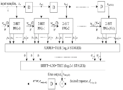
The proposed structure for error-computation unit of an N-tap DLMS adaptive filter is shown in figure 5. It consists of N number of 2-b partial product generators (PPG) corresponding to N multipliers and a cluster of L/2 binary adder trees, followed by a single shift–add tree.
Fig. 5. Proposed structure of the error-computation block.
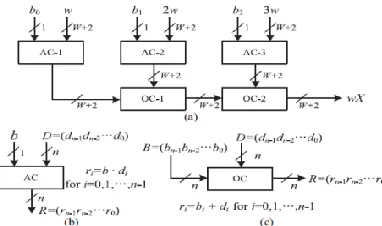
Stru ctu re o f PPG:
It consists of L/2 number of 2-to-3 decoders and the same number of AND/OR cells. Each of the 2-to-3 decoders takes a 2-b digit (u1u0) as input and produces three outputs b0 = u0. u1, b1 = u0 · u1, and b2 = u0 · u1, such that b0 = 1 for (u1u0) = 1, b1 = 1 for (u1u0) = 2, and b2 = 1 for (u1u0) = 3. The decoder output b0, b1 and b2 along with w, 2w, and 3w are fed to an AOC, where w, 2w, and
3w are in 2‟ s complement representation and
Available online:
https://edupediapublications.org/journals/index.php/IJR/
P a g e | 2011Stru ctu re o f A OCs :
The structure and function of an AOC are depicted in figure 6. Each AOC consists of three AND cells and two OR cells. The structure and function of AND cells and OR cells are depicted respectively. Each AND cell takes an n-bit input D and a single bit input b, and consists of n AND gates. It distributes all the n bits of input D to its n AND gates as one of the inputs. The other inputs of all the n AND gates are fed with the single-bit input b.
Fig. 6. Structure and function of AND/OR cell. Binary operators · and + in (b) and (c) are
implemented using AND and OR gates, respectively.
Stru ctu re o f A d d er Tree:
Conventionally, we should have performed the shiftadd operation on the partial products of each PPG separately to obtain the product value and then added all the N product values to compute the desired inner product. However, the shift-add operation to obtain the product value increases the word length, and consequently increases the adder size of N − 1 additions of the product values. To avoid such increase in word size of the adders, we add all the N partial products of the same place value from all the N PPGs by one adder tree.
The proposed design was coded in Verilog and synthesized. The word-length of input samples and
weights are chosen to be 8, with 16 bit internal representation. The convergence-factor was chosen to be a negative power of two to realize its multiplication through a simple shift operation. LSBs of the error and the weights are truncated to keep the word-length restricted to 8 bit. The structure of and the best of systolic structures were also coded in Verilog, similarly, and synthesized
using the same tool. A modified DLMS adaptive algorithm to achieve less adaptation-delay compared with the conventional DLMS algorithm, and shown that the proposed DLMS algorithm can be implemented efficiently by a pipelined inner product computation unit and parallel and pipelined weight update unit using carry-save reductions. Substantial reduction of adaptation-delay, ADP and EPS over the existing structures had been achieved by the proposed design. For 8-bit word length and filter order 32 the adaptation-delay of proposed structure is 3 cycles, which increases only by one cycle when the filter order increases by 16 times. Therefore, it can be used for large order adaptive filters as well. We are trying for further optimization of the structure by using suitable compressors.
IV RESULT A ND DISCUSSION
This section evaluates the performance of the proposed modified least mean square (LMS) algorithm and shows the simulation results. The first result declares about the output of LMS adaptive filter with delay. It is having some delay in the output of Least Mean Square adaptive filter. And the second result declares about the output of LMS adaptive filter without delay. After the clock input has given the output of the adaptive filter is achieved without delay. In order to reduce the adaptation delay in LMS algorithm, various architectures have been proposed. The changes have been made in the error computation block and weight update block.
Available online:
https://edupediapublications.org/journals/index.php/IJR/
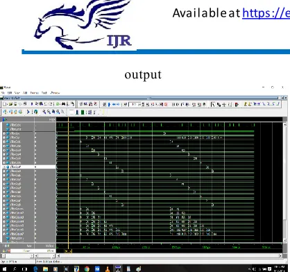
P a g e | 2012output
Fig. 8 Output waveform of LMS adaptive filter with error =1
The existing work on the DLMS adaptive filter does not discuss the fixed-point implementation issues, e.g., location of radix point, choice of word length, and quantization at various stages of computation, although they directly affect the convergence performance, particularly due to the recursive behaviour of the LMS algorithm. The output, from the LMS adaptive filter, has been monitored using the software tools .
V. CONCLUSION
We proposed an area–delay-power efficient low adaptation delay architecture for fixed-point implementation of LMS adaptive filter. Aside from this, we proposed a strategy for the optimized balanced pipelining across the time consuming blocks of the structure to reduce the adaption delay and power consumption as well. When the adaptive filter is required to be operated at a lower sampling rate, one can use the proposed design with a clock slower than the maximum usable frequency and a lower operating voltage to reduce the power consumption further.
REFERENCES
[1] P. K. Meher and S. Y. Park, “Low adaptation-delay LMS adaptive filter part-I: Introducing a novel multiplication cell,” in Proc. IEEE Int. Midwest Symp. Circuits Syst., Aug. 2011, pp. 1–4.
[2] P. K. Meher and S. Y. Park, “Low adaptation-delay LMS adaptive filter part-II: An optimized architecture,” in Proc. IEEE Int. Midwest Symp. Circuits Syst., Aug. 2011, pp. 1–4.
[3] P. K. Meher and M. Maheshwari, “A high-speed FIR adaptive filter architecture using a modified delayed LMS algorithm,” in Proc. IEEE Int. Symp. Circuits Syst., May 2011, pp. 121–124.
[4] L.-K. Ting, R. Woods, and C. F. N. Cowan, “Virtex FPGA implementation of a pipelined adaptive LMS predictor for electronic support measures receivers,” IEEE Trans. Very Large Scale Integr. (VLSI) Syst., vol. 13, no. 1, pp. 86–99, Jan. 2005.
[5] R. Rocher, D. Menard, O. Sentieys, and P. Scalart, “Accuracy evaluation of fixed-point LMS algorithm,” in Proc. IEEE Int. Conf. Acoust., Speech, Signal Process., May 2004, pp. 237–240.
[6] L. Van and W. Feng, "An efficient systolic architecture for the DLMS adaptive filter and its applications," IEEE Transactions on Circuits and Systems II: Analog and Digital Signal Processing, vol. 48, no. 4, pp. 359-366, Apr. 2001.
[7] S. Ramanathan and V. Visvanathan, “A systolic architecture for LMS adaptive filtering with minimal adaptation delay,” in Proc. Int. Conf. Very Large Scale Integr. (VLSI) Design, Jan. 1996, pp. 286–289.
[8] M. D. Meyer and D. P. Agrawal, “A high sampling rate delayed LMS filter architecture,” IEEE Trans. Circuits Syst. II, Analog Digital Signal Process., vol. 40, no. 11, pp. 727–729, Nov. 1993.
[9] H. Herzberg and R. Haimi-Cohen, “A systolic array realization of an LMS adaptive filter and the effects of delayed adaptation,” IEEE Trans. Signal Process. vol. 40, no. 11, pp. 2799–2803, Nov. 1992.
Available online:
https://edupediapublications.org/journals/index.php/IJR/
P a g e | 2013Bio Data
A u th o r
K.Srin iv as Red d y currently pursuing M.Tech in Electronics and Communication Engineering in Dept. of ECE, Sphoorthy Engineering College, Hyderabad, Telangana, India.
Co -A u th o r