Reactive Power Compensation Using
STATCOM for Single Phase Distribution
System
Lallu Sekharan1, Prof. Reenu George2, Prof. Emmanual Babu3
PG Student [PE], Dept. of EEE, Mar Athanasius College of Engineering, Kothamangalam, Kerala, India1
Professor, Dept. of EEE, Mar Athanasius College of Engineering, Kothamangalam, Kerala, India2,3
ABSTRACT: This paper presents a STATCOM based reactive power compensation control using MATLAB/SIMULINK. Whenever the reactive power compensation takes place at the distribution side for the different load condition, STATCOM plays a major role to support the reactive power compensation in generation and transmission system. With the PI controller, a reference voltage is generated with the sinusoidal PWM pulse which is to reduce the reactive power loss. The DC capacitor is used to maintain the constant energy at the input of the STATCOM. The STATCOM also reduces the harmonics present in the grid side. STATCOM is used to improve the power factor, and reactive power loss can be completely minimized. The voltage variation in the transmission line is also minimized with the help of STATCOM.
KEYWORDS: Static synchronous compensator (STATCOM), Sine PWM, Proportional Integral controller.
I. INTRODUCTION
In Alternating Current transmission and distribution system reactive power is a great concern which determines the quality of power. The total power in AC network was calculated as the algebraic sum of real and reactive power .From this the compensation of reactive power improves the power quality. In older days there active power was compensated by using reactors and capacitors. For various loads multiple numbers of reactors and/or capacitors were required. This type of compensation was complicated when non-linear loads are applied and also leads to higher cost and maintenance. In this work there active power compensation for non-linear load was proposed by using STATCOM [1].
In this system single DC link capacitor was used for compensation. The capacitor will acts as an input for an inverter.. By varying the pulse width of the inverter the compensation was achieved. STATCOM is one of the FACTS family device which was recently used for reactive power compensation. In STATCOM only one capacitor and reactor are used for reactive power compensation. Normally the reactor acts as alter for the inverter and the capacitor acts as the input for the inverter. STATCOM is operated as a shunt connected static VAr compensator based voltage and current source converter whose capacitive and inductive current can be controlled with ac voltage[2].
Here the closed loop control of STATCOM was achieved by using PI controller .STATCOM is to be able to exchange reactive power with the ac power network (i.e., to a value high enough for the STATCOM to be able to produce ac voltage at the value required). The voltage across the capacitor is maintained at the required value by continually adjusting the magnitude and polarity of the active component of the current at the ac side of the STATCOM. When the voltage across the capacitor needs to be increased, the STATCOM adjusts the magnitude and polarity of the active component of the current owing through its ac side so that active power is drawn from the ac power system and converted to dc power in order to charge the capacitor[3]
In this study sinusoidal PWM is used as control signal. The circuit conditions for a 1000w load ,before and after compensation using STATCOM is obtained. From the corresponding waveforms, we can analyse that by using STATCOM, Power factor can be improved to Unity . And also ,we can suppress the effect of sag by injecting appropriate amount of current in to the power system.
II. REACTIVE POWER
The work producing power, measured in watts (W), or kilowatts (kW) is considered to be the real power. Real power produces the mechanical output of a motor. Reactive power is not used to do work but it is needed to operate apparatus and is measured in Volt-Amperes-reactive (VAr) or (kVAr). If the load is pure resistive, then it doesn't need to worry about the reactive power. However ,most of the loads are not purely resistive. It may be moreover inductive or capacitive in nature. For this type of loads, reactive power compensation is required
.
Fig.1: Power Triangle S=P+jQ
From the power triangle, it is clearly known that compensation of reactive power decreases, as the apparent power equals the real power. Thus, the total consumption of apparent power is also reduced.
VOLTAGE SOURCE CONVERTER (VSC)
A voltage-source converter is a power electronic appliance, which generate and a sinusoidal voltage with any essential magnitude, frequency and phase angle. Voltage source converters are widely used in adjustable speed drives, but can also be used to mitigate voltage sags. The VSC is used either to totally change the voltage or to add the missing voltage’ in the transmission line. The ‘missing voltage’ is the difference between the nominal voltage and the actual voltage. The converter is generally based on various kind of energy storage, which will supply
the converter with a DC voltage. The solid state electronics base converter is then,switched to get the preferred output voltage. Normally the VSC is used for voltage sag/swell mitigation.but also used for power quality issues like flicker and harmonics that are produced in network ac system.
A STATCOM is a device that compensates the reactive power and provide and the voltage support to an AC system. Due to the advance of technique of power electronics devices,VSC-based converters have been increasingly used in STATCOM systems. The normal VSC-based STATCOM consists of a voltage source converter,linked to an energy storage device on one side and to the AC power system on the other-hand, and a control system based on the conventional method with system controller.When utility source is injecting the power to the load then the reactive power demand takes place in the distribution system due to the inductive nature of load[5]. By measuring the reference voltage by PI controller, and by minimizing the error, the conduction pulse width of inverter switches are controlled for reactive power injection in the line by the STATCOM. The Power factor is maintained as unity at the generation side of the distribution system. So the utility does not need to take care of or de liver the reactive power to the load’s VAr demand. STATCOM injects the required reactive power to the distribution system to improve the power factor, voltage stability.
CONTROLLER
problem. The controller input is an error signal obtained from the reference voltage and RMS is measured. Error is processed by a PI controller the output is the angle which provides the PWM indicate generation. The active and reactive power exchange with the network simultaneously: an error signal is obtained by comparing the reference voltage with the RMS voltage measured at the load point. PI controller produces the error signal generate the required angle to make the error with zero, i.e., the load RMS voltage is brought back to the reference voltage. The voltage and reactive values are compared in PI controller and error signal is calculated and minimised. The signal from controller is given to the hysteresis control compares the input current and reference current and adjusts the dc voltage to remain as constant in the distribution system.
III. RESULTS AND DISCUSSION
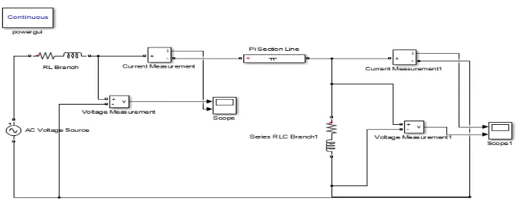
Fig.2: Simulation model of circuit before compensation
Fig 3 shows the output voltage and current are out of phase in source side before compensation.
Fig.3: Simulation result of circuit before compensation
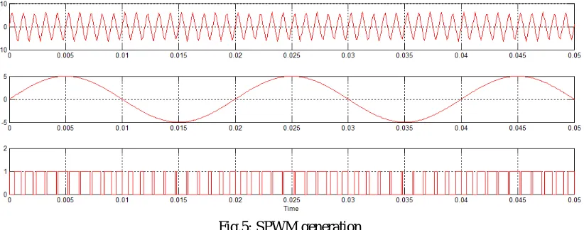
Fig 4 shows the Sine PWM generation circuit.
Fig 5 shows the Sine PWM generation .which is used here as control pulse.
Fig.5: SPWM generation
Fig 6 shows the circuit after compensation ,that is with STATCOM.
Fig.6: Simulink model of circuit using STATCOM
Fig 7 shows Grid voltage under normal working condition of the power system.
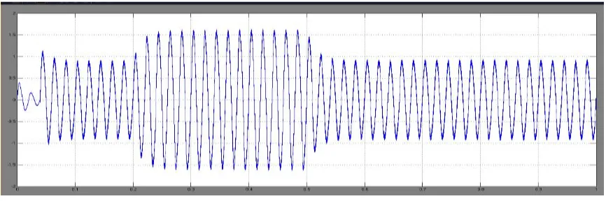
Fig 8 shows sudden decrease in voltage when a sag condition occurs.
Fig.8: Sag voltage without STATCOM
Fig 9 shows injection of current in to the power system in order to compensate the sag condition by the STATCOM
Fig.9: STATCOM current during Sag
Fig 10 shows comparison of results before and after compensation. In the first waveform (without STATCOM) the voltage and current are out of phase. In the second waveform (with STATCOM) voltage and current are in phase. That is we get unity power factor by using STATCOM.
SIMULATION PARAMETERS
Table shows the simulation parameters without and with using STATCOM for a 1000w load.
Table: 1 Parameters before compensation Table: 2 Parameters after compensation
Real Power (Watts) Reactive Power(VAr) Power Factor
Source 1353 1133 .7667
Load 1188 969.3 .7684
IV. CONCLUSIONS
In this study the reactive power compensation for single phase distribution system with RL load has been implemented using a single phase shunt connected voltage source converter . The VSI is made to act as the STATCOM by maintaining the DC Voltage level across the DC input side of the VSI. A separate control logic is implemented to draw a mild amount of real power (p) from the grid itself to charge the D.C capacitor ,STATCOM as rectifier and separate control strategies are involved to make the STATCOM to work as reactive current source in to and from direction with respect to grid and STATCOM (as reactive power compensator).The shunt connected VSI may also be extended to mitigate harmonics also. The MATLAB-SIMULINK work is done for a capacitor of 1000 WATTS. Here 1000 W RL load has been taken. The reactive power compensated using STATCOM and the power factor which is maintained as unity. The load required 709 VAr reactive power is delivered from STATCOM not from source. Closed loop PI controller has been developed for improving the power factor and to compensate the reactive power. So the quality of the input power was improved in the utility side.
REFERENCES
[1] Arvindpahade,nitinsaxena “Transient stability improvement by using shunt FACT device (STATCOM) with Reference Voltage Compensation (RVC) control scheme”International Journal of Electrical, electronicsissn No. (Online) : 2277-2626 and Computer Engineering 2(1): 7- 12(2013)
[2] P. S. Sensarma, K. R. Padiyar, V. Ramanarayanan” Analysis and Performance Evaluation of a Distribution STATCOM for Compensating Voltage Fluctuations” IEEE Transactions On Power Delivery,Vol. 16, No. 2, April 2001
[3] Sheng Wang , Lixue Li , Xin Wang , Yihui Zheng , Gang Yao,”Direct output voltage control of a STATCOM using PI controller based on multiple models”, Industrial Electronics and Applications (ICIEA), 2011 6th IEEE Conference on DOI:10.1109/ICIEA.2011.59759
[4] Yiqiao Liang, C. O. Nwank ‘’A New Type of STATCOM Based on Cascading Voltage- Source Inverters with Phase-Shifted Unipolar SPWM” IEEE Transactions On Industry Applications, Vol. 35, No.5, September/October 1999
[5] J. W. Dixon, Y. del Valle, M. Orchard, M.Ortúzar, L. Morán, and C. Maffrand, “A full compensating system for general loads, based on a combination of thyristor binary compensator, and a PWM-IGBT active power filter,” IEEE Trans. Ind. Electron., vol. 50, no.5, pp. 982–989, Oct. 2003.
[6] R. Bojoi, L. Limongi, D. Roiu, and A. Tenconi, “Enhanced power quality control strategy for single-phase inverters in distributed generation sys- tems,” IEEE Trans. Power Electron., vol. 26, no. 3, pp. 798–806,Mar. 2011
[7] Clark Hochgraf , Robert H. Lassete “Statcom Controls for Operation with Unbalanced Voltages“IEEE Transactions on Power Delivery, Vol. 13, No. 2, April 1998
[8] S. Bhattacharya, B. Fardenesh, B. Shperling, and S. Zelingher, “Convertible static compensator: Voltage source converter based FACTS application in the New York 345 kV transmission system,” inInt.Power ElectronicsConf. (IPEC 2005)2005,pp. 2286–2294
Real Power (Watts) Reactive Power(VAr) Power Factor
Source 1617.53 652.1 .9978
Load 642.6 674.6 .707