Simulation and Analysis of Adaptive Control
Method Employed for Matrix Converter
Dr. M.Vijaya Kumar1, G.Pandu Ranga Reddy2,J.N.Chandra Shekar3, Santhi.M,M4
Professor, Dept. of EEE, J.N.T.U. Anantapur, India 1 Associate Professor, Dept. of EEE, G.P.C.E.T, Kurnool, India 2 Assistant Professor, Dept. of EEE, SV University, Tirupati, India 3
PG Student, Dept. of EEE, SV University, Tirupati, India4
ABSTRACT: Since discovered, electrical energy became one of the world’s fastest growing energy technologies.
Efficient and stable utilization of electrical energy is one of the most important problem. The major phenomena that effects on the quality of power supply is the harmonics caused by different loads connected to the grid, which are usually converters based on power electronic components. These are the main causes for the deterioration of power quality. This paper presents the harmonic compensation of linear loads fed by matrix converter and the performance of two types of controllers(namely, Adaptive Fuzzy control and Adaptive Neural Fuzzy Inference system) are compared, during balanced supply and abnormal grid conditions. The sinusoidal nature of output currents were preserved by using PWM method and optimum Venturini method employed for matrix converter.
KEYWORDS: Matrix converter, Balanced and Unbalanced grid, Adaptive fuzzy control, ANFIS controller, Venturini
modulation, Linear load, THD.
I. INTRODUCTION
The control and transformation of electrical energy is the most important process in electrical engineering. Due to the advancements of power electronics in recent years ,this work has been done by using power semiconductors and energy storage elements such as capacitors and inductors. Their response is instantaneous and automatically adapts to the changes during abnormal conditions. The increased complexity of their control and usage of more number of elements leads to the discovery of new type of converter called matrix converter which is very simple and compact. A Matrix Converter is an array of semi-conductor controlled switches used for converting directly AC energy into AC energy without any intermediate dc link. The main feature of this device is to convert the magnitude as well as the frequency of the input to a desired magnitude and frequency of the output. Basically a matrix converter consists of nine bi-directional switches, which are required to be commutated in the right way and sequence in order to minimize losses and produce the desired output waveforms with high quality. The Factors such as the absence of bulky electrolytic capacitors, reduction in size and weight of the converter, increasing power density, and obtaining almost sinusoidal nature of output wave forms are the most important characteristics of matrix converter. This paper presents the adaptive control techniques for the performance improvement of matrix converter along with Optimum Amplitude Venturini Modulation to get maximum voltage transfer ratio and to enhance the overall system stability.
II. LITERATURE SURVEY
array of semiconductor switches connected directly between the input and output terminals. The most common topology for an indirect AC/AC converter is the use of diode bridge rectifier at the supply side and a pulse width modulated voltage source inverter (PWM-VSI) at the load side .This converter consists of two power conversion stages and an intermediate energy storage element. In the first stage the input AC power is converted to uncontrolled DC power by the diode bridge rectifier. The converted DC power is then stored in DC link capacitor. In the second stage a PWM-VSI operating at a high switching frequency generates AC signals with arbitrary amplitude and frequency. Although this type of AC/AC converter is very cost-effective and reliable, it has lots of drawbacks. Due to the uncontrolled operation of diode bridge rectifier, the input AC currents drawn by the rectifier contain a large amount of harmonics that produces distortion of the input line voltages, having a negative impact on the performance of sensitive loads and equipment connected to the same supply.
The other topology called matrix converter for 3 AC/AC power converter replaces the diode bridge with PWM rectifier resulting in a back-to-back converter .This converter overcomes the input harmonic problem of the former topology and offers improved total input power factor and bi-directional power flow. The matrix converter was firstly introduced in the year 1976 by Venturini and Alesina with their intensive research on MC's and they proposed a generalised high-frequency switching strategy with huge mathematical background in 1980.They have represented the power circuit of the converter as a matrix. The main theme of this control strategy is to design an ideal electronic transformer which is capable of varying the current, voltage, power factor and frequency. [1]
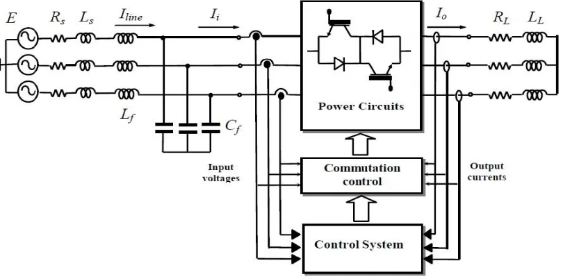
II. THE BASIC TOPOLGY AND MODELLING OF MATRIX CONVERTER
Fig. 1 Basic circuit of a Matrix Converter
A. Modelling of the Matrix Converter
The input source voltage of matrix converter is given by:
( ) = ( ) ( ) ( ) = cos( )
cos( − )
cos( − )
(1)
The input line current amplitude and phase of matrix converter is given by:
( ) = ( ) ( ) ( ) = ⎣ ⎢ ⎢ ⎢
⎡ cos( + )
cos( −2
3 +
cos( −4
3 + )⎦
⎥ ⎥ ⎥ ⎤
(2)
The most efficient approach to obtain desired output voltage and currents are determined respectively by following equations: ( ) = ( ) ( ) ( ) = cos( )
cos( − )
cos( − )
(3) ( ) = ( ) ( ) ( ) = ⎣ ⎢ ⎢ ⎢
⎡ cos( + )
cos( −2
3 +
cos( −4
3 + )⎦
⎥ ⎥ ⎥ ⎤
(4)
The nine ideal semiconductor switches of this converter are represented by and are characterised a connection function ( ) defined by the following equations:
( ) = 0
1 (5) + + = 1, where = , , and = , ,
The generation function ( ) of the nine bidirectional switches as the average value of the connection function (t) over a period of switching TP are defined as follows:
( ) = ∫ ( ) ℎ 0 < ( ) > 1 (6)
The matrix converter is fed by voltage source, so in order to prevent the short-circuit on the input side and to provide uninterrupted current flow, input terminals should not be short circuited and the output phase must never be opened .For this reason the duty cycles must satisfy the following constraints.
( ) + ( ) + ( ) = 1
( ) + ( ) + ( ) = 1 (7)
( ) + ( ) + ( ) = 1
All the generation functions form a matrix called modulation matrix M (t) as:
( ) = (8)
The conversion matrix of matrix converter connects the electrical as follows:
( ) = ( ). ( ) (9) ( ) = ( ) . ( ) (10)
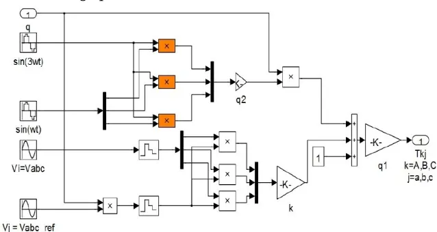
B. PWM with three intervals using Optimum Venturini Control
Fig. 2 Simulink model of matrix converter to generate duty cycle for three output phases
In order to obtain maximum output voltage, it is necessary to add third harmonic frequency component of the input and output frequencies to the initial approach of Venturini method as shown in fig. 2 ,which indicates the following equations. This is called Optimum Amplitude Venturini method [2],[3],[4].
( ) = (cos( )− cos(3 ) +
√ (3 ))
( ) = (cos +2
3 −
1
6cos(3 ) +
1
2√3 (3 ))
( ) = (cos + − cos(3 ) +
√ (3 )) (11)
The modulation rate (q) is the ratio between the maximum amplitude of the output voltage ( ) and the maximum amplitude of the input voltage ( ) and it can be raised to 0.866 against the maximum value of 0.5 by injecting third harmonic output frequency component to the output voltages which can be determined by the following equation (12).
q = ( )
( ) ℎ 0 < ≥ 0.866 (12)
Similarly, the modulation function according to the optimal amplitude in expression of Venturini is:
1 +2 + 4
3.√3sin( ) sin(3 )
( ) =1
3 1 + 2
+ 4
3.√3sin( + 2
3) sin(3 ) 1 + +
.√ sin( + ) sin(3 ) (13)
By using the following equation the switching time were calculated :
( ) = ( ) (14)
The carrier signal is tooth expressed by:
( ) = 0≤ ≥ (15)
Fig. 3 Obtaining turn-on-time of the switches
The fig. 3 represents the turn-on time of the bidirectional switches for one output phase. The controls of switches of Matrix converter are obtained using a simple logic binary:
=
= +
=
=
= (16)
III. DESIGNING OF CONTROLLERS
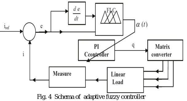
A. Adaptive Fuzzy control of a matrix converter
Fig. 4 Schema of adaptive fuzzy controller
The output current measurements of the linear RL load using adaptive fuzzy controller as given in Fig. 4.[5]. The load current and it's reference output load current are measured the according to the following equation:[6]
= ′ ( ) + ′ ( ) + ′ ( ) (17)
= ′ ( ) + ′ ( ) + ′ ( ) (18)
Table 1: Fuzzy rules of inference
e
de NB NM NS ZE PS PM PB
NB NB NB NM NM NS NS ZE
NM NB NM NM NS NS ZE PS
NS NM NM NS NS ZE PS PS
ZE NM NS NS ZE PS PS PM
PS NS NS ZE PS PS PM PM
PM NS ZE PS PS PM PM PB
PB ZE PS PS PM PM PB PB
B. Adaptive Neural Fuzzy Inference System (ANFIS) of a matrix converter
The ANFIS controller is combined with the inference systems fuzzy logic and artificial neural network. Artificial neural network can be trained online or offline learning process. The ANFIS structure is composed of five functional blocks namely rule base, database, decision making unit, fuzzification and defuzzification interface. The ANFIS controller inputs are error from the measured load and reference currents and the derivative of error. The error signals are multiplied by their respective weights and mapped through fuzzy logic membership functions. Training the ANFIS system is actually tuning the weights to get desired value of "q".
Fig. 5 ANFIS structure layers and rules formation
The rules of the ANFIS structure are shown in Fig.5.The output of the ANFIS controller generates the required voltage ratio according to the changes in input and the duty cycles are generated according to it.
IV. SIMULAITON RESULTS
The adaptive fuzzy and ANFIS controllers are connected to the matrix converter and a set of simulations have been performed. And a comparison is made between adaptive fuzzy controller and ANFIS controller. Bidirectional switches IGBT are considered and ode23tb simulation solver was used .
A. Balanced Grid Case
Time (sec)
Fig. 6 Input voltage source
Figure 6 represents the input voltage of 311V supplying linear load without any disturbances which indicates that the supply is free from harmonics and its total harmonic distortion is 0.00%
Time (sec)
Fig. 7 Linear load current (Adaptive fuzzy controller)
Whereas Figure 7 represents the load currents of three output phases for linear RL load when matrix converter is connected to adaptive fuzzy controller under balanced grid conditions.
Fig. 8 Harmonic spectrum analysis of linear load current (Adaptive fuzzy controller)
Figure 8 represents the harmonic content of 3.44% present in the output current waveform by using adaptivefuzzy controller without any disturbances in the supply.
Time (sec)
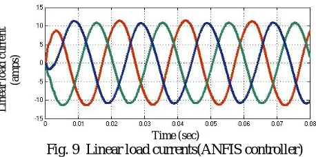
Fig. 9 Linear load currents(ANFIS controller)
The above figure 9 shows the linear load currents of RL load for three output phases when the matrix converter is controlled by ANFIS controller when the supply is balanced.
In
p
u
t
v
o
lt
a
g
e
(v
o
lt
s)
L
in
e
a
r
lo
a
d
c
u
rre
n
t
(a
m
p
s)
L
in
e
a
r
lo
a
d
c
u
rre
n
t
(a
m
p
Fig. 10 Harmonic spectrum analysis of linear load current (ANFIS controller)
From the Figure 10 which represents the THD of 3.24% for linear load currents indicates that ANFIS controller gives better results than adaptive fuzzy controller.
B. Unbalanced Grid Case
Time(sec)
Fig. 11 Disturbed Input voltage source
The abnormal grid voltages are applied to the matrix converter by injecting 20% third and 10% fifth harmonic with THD of 22.36%. Figure 11 represents the distortion in source voltage and in practical these disturbances are occurred due to sudden load variations, faults in the power system network and electronic goods etc.
Time(sec)
Fig. 12 Linear load current (Adaptive fuzzy controller)
Even though the input voltage is disturbed the adaptive fuzzy controller still maintains the sinusoidal nature of load currents which is represented in the Figure 12.
Fig. 13 Harmonic spectrum analysis of load current for unbalanced grid case (Adaptive fuzzy controller)
D
is
tu
rb
e
d
V
o
lt
a
g
e
S
o
u
rc
e
(v
o
lt
s)
L
in
e
a
r
lo
a
d
c
u
rre
n
t
(a
m
p
The above figure shows the harmonic content of 7.99% for linear load current when the matrix converter is fed through adaptive fuzzy controller .
Time(sec)
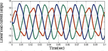
Fig. 14 Linear load current (ANFIS controller)
Figure 14 represents the linear load currents of RL load for three output phases when the matrix converter is fed through ANFIS controller when the supply is disturbed.
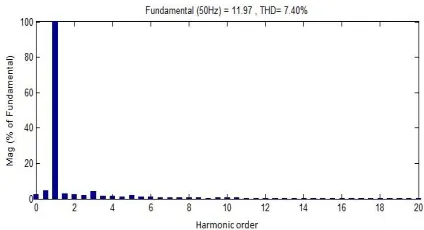
Fig. 15 Harmonic spectrum analysis of load current for unbalanced grid case (ANFIS controller)
The above figure shows that 7.40% of harmonics are present in the output currents using ANFIS controller. The above simulation results obtained in all the cases for RL load shows that the sinusoidal nature of linear load currents are preserved in any condition and the ANFIS controller continuously adjusts to both normal and abnormal conditions much better than adaptive fuzzy controller. At the same time ANFIS controller shows the better performance in suppressing the harmonics of linear load currents in terms of THD, which is compared with the adaptive fuzzy control in the below table[8].
Table 2: Comparison table between Adaptive Fuzzy and ANFIS controllers in terms of THD
Input Voltage(THD)
Linear Load current(THD)
Adaptive Fuzzy Controller
ANFIS controller
Balanced Grid Case
0.00% 3.44%
3.24%
Unbalanced Grid Case
22.36% 7.99% 7.40%
L
in
e
a
r
lo
a
d
c
u
rre
n
t
(a
m
p
V. CONCLUSION
In this paper in order to evaluate the effectiveness of the results two types of controllers adaptive fuzzy controller and ANFIS controllers were used along with different cases of harmonic disturbances. The above results clearly shows that the ANFIS controller gives better results than adaptive fuzzy control and it preserves the sinusoidal nature of linear load currents. The Matrix converter along with the ANFIS controller can also be used for different loads and by further improvements it can be used in various applications like aircrafts, wind generating stations and induction motors.
REFERENCES
[1] S. L. Arevalo, Matrix Converter for Frequency Changing Power Supply Applications, Submitted to the University of Nottingham for the degree of Doctor of Philosophy, January 2008.
[2] H. Karaca, R. Akkaya, H. Doğan, A Novel Compensation Method Based on Fuzzy Logic Control for Matrix Converter under Distorted Input Voltage Conditions», Proceedings of the International Conference on Electrical Machines, 2008.
[3] S. M. Barakati , Modeling and Controller Design of a Wind Energy Conversion System Including a Matrix Converter , thesis of Doctor of Philosophy in Electrical and Computer Engineering Waterloo, Ontario, Canada, 2008.
[4] L. Zarri, Control of Matrix Converters , Ph. D. in Electrical Engineering XIX year power electronics, machines and drives (ING-IND/32), University of Bologna. 2007.
[5] Hulusi Karaca, Student Member, IEEE, Ramazan Akkaya, Hüseyin Do an. A Novel Compensation Method Based on Fuzzy Logic Control
for Matrix Converter under Distorted Input Voltage Conditions. Proceedings of the 2008 InternationalConference on Electrical Machines, 2008.
[6] M. Venturini and A. Alesina, “The generalised transformer: new bidirectional sinusoidal waveform frequency converter with continuously adjustable input power factor”, in Conf. Rec. IEEE PESC’80, pp. 242-252.
[7] N. J. Mason, BEng, Space Vector Modulation of a 4-Leg for the Matrix Convert Thesis submitted to The University of Nottingham degree of
Doctor of Philosophy, November, 2011
[8] IEEE Standard 1992, \IEEE recommended practices and requirements for harmonic control in electrical power systems," IEEE Std
519-1992, 12 April.1993.
APPENDIX SYSTEM PARAMETERS:
Input voltage phase to neuter RMS: =220V
Input frequency =50 Hz
Input filter: = 0.8Ω, = 0.5 , = 80µ .
Switching frequency : =5 kHz