ISSN (Print) : 2320 – 3765
ISSN (Online): 2278 – 8875
I
nternational
J
ournal of
A
dvanced
R
esearch in
E
lectrical,
E
lectronics and
I
nstrumentation
E
ngineering
(A High Impact Factor, Monthly, Peer Reviewed Journal)
Website: www.ijareeie.com
Vol. 8, Issue 3, March 2019
Field Programmable Gate Array (FPGA)
Based Speed Control of 3-Φ Induction Motor
Drives
Mohit Kumar Yadav1 , Sumati Srivastava2
PG Student [Power System], Dept. of EEE, Maharishi University of Information Technology, Lucknow, U.P., India1
Asst. Professor, Dept. of EEE, Maharishi University of Information Technology, Lucknow, U.P., India2
ABSTRACT: The induction motor is without doubt the most used electrical motor because of its unique characteristics. Induction motors are the most common motors used in industrial motion control system due to its low-cost, simple and rugged design.. In this paper a closed loop speed control strategy is implemented of Variable-Voltage Variable-Frequency (VVVF) method based on sinusoidal pulse width modulation technique (SPWM) for a three phase induction motor using a FPGA. The field programmable gate array (FPGA) technology provides programmable system-on-chip (PSoC) environments for designing modern digital ASIC controllers for specific applications. The speed control program has been developed in Xilinx 12.1 software using VHDL language. The performance of the proposed FPGA based drive is compared with soft drive approach in Electrical Machine Laboratory where variable voltage and frequency power supplies are used for motor speed control. Simulation and experimental results, given to verify the implemented SPWM control IC, demonstrate that FPGA-based solution for induction motor drive is flexible, low cost and high-performance.
KEYWORDS: Induction motors, VVVF controller, PWM inverter, FPGA Induction motor drives, field-programmable gate arrays (FPGAs), sinusoidal PWM, speed control.
I.INTRODUCTION
In recent years, microcontrollers, Digital Signal Processors (DSPs), DSPic have been widely used for implementing digital motor control algorithms in industry. But it has some disadvantages like, long development period and poor software portability and re-usability. Any change in the microprocessor program, imposed by the introduction of new features or the need of better performance require a huge revision of the project, in order to fit with the new system. To satisfy these demands a FPGA based hardware implementation technology are used. For speed control of three phase induction motor, Pulse Width Modulation (PWM) inverters are used and more popular in ac motor drive applications. PWM inverters make it possible to control both the frequency and magnitude of the voltage applied to a motor. The speed control of a three-phase induction motor can be performed using algorithms open loop or closed loop V/f control approach. A Closed loop operation of induction motors in the so-called constant volts/hertz (V/f) mode has been known for many decades and its principle is well understood [1]. With the introduction of solid state inverters the constant V/f control became popular and the great majority of variable speed drives in operation today are of this type.
ISSN (Print) : 2320 – 3765
ISSN (Online): 2278 – 8875
I
nternational
J
ournal of
A
dvanced
R
esearch in
E
lectrical,
E
lectronics and
I
nstrumentation
E
ngineering
(A High Impact Factor, Monthly, Peer Reviewed Journal)
Website: www.ijareeie.com
Vol. 8, Issue 3, March 2019
II.FPGA (Field Programmable Gate Array)
Microprocessor based controllers are more economical, but often face difficulties in dealing with control systems that require high processing and input/output handling speeds. In recent years, Field Programmable Gate Arrays have drawn much attention due to its short design cycle, low cost and high flexibility in terms of programmability. The Field Programmable Gate Arrays (FPGAs) offer significant advantages over microprocessors and DSPs for high performance, low volume applications; particularly for applications that can exploit customized bit-widths and massive instruction-level parallelism [1].
A field programmable gate array is a set of digital logic gates and logic blocks which can be reprogrammed to meet the desired motor-control features [8]. While the assembly and high level languages like C are used by microcontrollers and DSPs, the technology independent hardware description languages including VHDL [9] and Verilog [10] are used to program FPGAs
III. BLOCK DIAGRAM
The closed loop V/f controller for the three phase induction motor using FPGA technique is presented. The block diagram explains the concept of this system is shown in fig.1. The diode bridge wave rectifier is used to convert input AC supply into DC as shown in Fig.1. Capacitor is used to remove the ripples in the output of the rectifier.
Fig. 1 Block diagram of proposed system.
ISSN (Print) : 2320 – 3765
ISSN (Online): 2278 – 8875
I
nternational
J
ournal of
A
dvanced
R
esearch in
E
lectrical,
E
lectronics and
I
nstrumentation
E
ngineering
(A High Impact Factor, Monthly, Peer Reviewed Journal)
Website: www.ijareeie.com
Vol. 8, Issue 3, March 2019
In time, a maximum of three switches will be on, either one upper and two lower switches, or two upper and one lower switch. When switch turns on, current flows from the DC bus to the motor winding. Because the motor windings are highly inductive in nature, they hold electric energy in the form of current. This current needs to be dissipated while switches are off. Diodes connected across the switches give a path for the current to dissipate when the switches are off. These diodes are also called freewheeling diodes. Upper and lower switches of the same limb should not be switched on at the same time. This will prevent the DC bus supply from being shorted. A dead time is given between switching off the upper switch and switching on the lower switch and vice versa. Dead time of 2.5 microseconds is coded in FPGA program.
Speed sensors are used to find speed of the rotor. This sensor is used to give speed feedback to the FPGA controller. The FPGA controller receives the actual speed of three phase induction motor from the speed sensor and set speed from keyboard. Then controller compares the actual speed obtained from sensor and desired (set value). The difference between them is taken as error and this value is stored in PWM duty cycle register. Then with corresponding value of error, the modulating signal generated. The generated signal compared with carrier signal, which results in the PWM signal. These generated PWM signals are applied to inverter in turn controls the speed based on variable voltage and variable frequency method.
IV.MATLAB Code
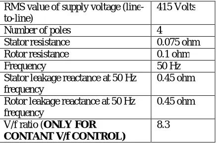
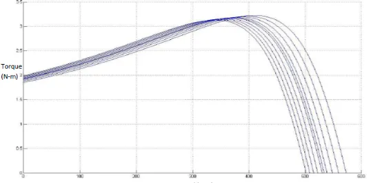
A MATLAB code was developed to observe the variation of frequency as well as the operating zone of the motor with the variation of load torque. Along with the frequency, the voltage was also varied to make V/f ratio constant so that the air gap flux and the maximum torque remain constant. The MATLAB code is given and the output Torque-Speed characteristics are shown in Figure 2 below. The machine details used for the code execution are shown in Table 1.
function out = inductionconstVf()
Vll=input('Suppy Voltage (line to line) RMS value @ 50 Hz: ');
f2=input('Enter the second frequency: ');
f3=input('Enter the third frequency: ');
f4=input('Enter the fourth frequency: ');
f5=input('Enter the fifth frequency: ');
P=input('Enter the number of poles: ');
Rs=input('Stator Resistance: ');
Rr=input('Rotor Resistance: ');
Xs=input('Stator Leakage Reactance @ 50 Hz frequecny: ');
Xr=input('Rotor Leakage Reactance @ 50 Hz frequecny: ');
Ls=Xs/(2*pi*50); Lr=Xr/(2*pi*50);
Vlnf1=Vll/(3^0.5); Vlnf2=Vlnf1*f2/50; Vlnf3=Vlnf1*f3/50; Vlnf4=Vlnf1*f4/50; Vlnf5=Vlnf1*f5/50;
ISSN (Print) : 2320 – 3765
ISSN (Online): 2278 – 8875
I
nternational
J
ournal of
A
dvanced
R
esearch in
E
lectrical,
E
lectronics and
I
nstrumentation
E
ngineering
(A High Impact Factor, Monthly, Peer Reviewed Journal)
Website: www.ijareeie.com
Vol. 8, Issue 3, March 2019
Wsync5=4*pi*f5/P;
Tmf2=zeros(Wsync2*500+1,1); Tmf3=zeros(Wsync3*500+1,1); Tmf4=zeros(Wsync4*500+1,1); Tmf5=zeros(Wsync5*500+1,1);
Tmf1=zeros(Wsync1*500+1,1);
m=1;
for Wrotor1=0:0.002:Wsync1
Tmf1(m)=(3*(((Vlnf1^2)*Rr/((Wsync1-Wrotor1)/Wsync1))/((Rs+Rr/((Wsync1-Wrotor1)/Wsync1))^2+(2*pi*50*Ls+2*pi*50*Lr)^2))/Wsync1); %star connected m=m+1;
end
m=1;
for Wrotor2=0:0.002:Wsync2
Tmf2(m)=(3*(((Vlnf2^2)*Rr/((Wsync2-Wrotor2)/Wsync2))/((Rs+Rr/((Wsync2-Wrotor2)/Wsync2))^2+(2*pi*f2*Ls+2*pi*f2*Lr)^2))/Wsync2);
m=m+1;
end
m=1;
for Wrotor3=0:0.002:Wsync3
Tmf3(m)=(3*(((Vlnf3^2)*Rr/((Wsync3-Wrotor3)/Wsync3))/((Rs+Rr/((Wsync3-Wrotor3)/Wsync3))^2+(2*pi*f3*Ls+2*pi*f3*Lr)^2))/Wsync3);
m=m+1;
end
m=1;
for Wrotor4=0:0.002:Wsync4
Tmf4(m)=(3*(((Vlnf4^2)*Rr/((Wsync4-Wrotor4)/Wsync4))/((Rs+Rr/((Wsync4-Wrotor4)/Wsync4))^2+(2*pi*f4*Ls+2*pi*f4*Lr)^2))/Wsync4);
m=m+1;
end
m=1;
for Wrotor5=0:0.002:Wsync5
Tmf5(m)=(3*(((Vlnf5^2)*Rr/((Wsync5-Wrotor5)/Wsync5))/((Rs+Rr/((Wsync5-Wrotor5)/Wsync5))^2+(2*pi*f5*Ls+2*pi*f5*Lr)^2))/Wsync5);
m=m+1;
end
ISSN (Print) : 2320 – 3765
ISSN (Online): 2278 – 8875
I
nternational
J
ournal of
A
dvanced
R
esearch in
E
lectrical,
E
lectronics and
I
nstrumentation
E
ngineering
(A High Impact Factor, Monthly, Peer Reviewed Journal)
Website: www.ijareeie.com
Vol. 8, Issue 3, March 2019
plot(Tmf3); plot(Tmf4); plot(Tmf5); hold off;
ylabel('Torque(N-m)');
xlabel('Rotor Speed(Rad/s) * 100');
end
RMS value of supply voltage (line-to-line)
415 Volts
Number of poles 4
Stator resistance 0.075 ohm Rotor resistance 0.1 ohm Frequency 50 Hz Stator leakage reactance at 50 Hz
frequency
0.45 ohm
Rotor leakage reactance at 50 Hz frequency
0.45 ohm
V/f ratio (ONLY FOR CONTANT V/f CONTROL)
8.3
Table 1: Machine details used in MATLAB codes execution for variable rotor resistance, variable stator voltage and constant V/f control
Figure 2: Input Data (Machine details) for Closed loop Constant V/f Speed Control Method
V. IMPLEMENTATION of SOFTWARE
ISSN (Print) : 2320 – 3765
ISSN (Online): 2278 – 8875
I
nternational
J
ournal of
A
dvanced
R
esearch in
E
lectrical,
E
lectronics and
I
nstrumentation
E
ngineering
(A High Impact Factor, Monthly, Peer Reviewed Journal)
Website: www.ijareeie.com
Vol. 8, Issue 3, March 2019
write coding. Sparten 6 development board has 20MHz clock signal by default i.e. each clock cycle is 50ns. The firmware code is developed based on this frequency.
VI. SIMULATION AND RESULTS
Here simulation and results are discussed. For simulation MATLAB/SIMULINK is used and simulation is verified for this drive at various set speed. This drive system consists of a single phase diode bridge rectifier, six switch three phase inverter and 3- phase squirrel cage Induction Motor.
Fig. 3: Simulink diagram
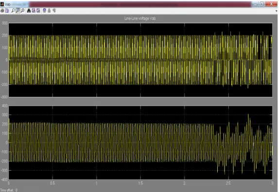
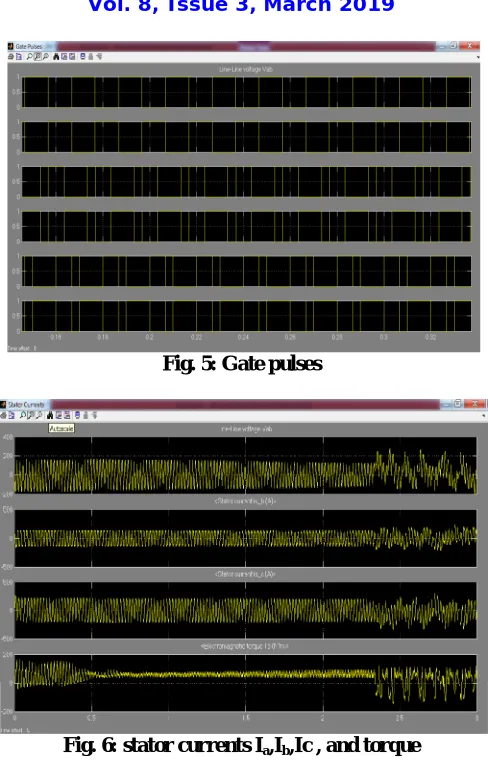
Input supply voltage: 1-phase, 230 V (rms), 50 Hz. Induction Motor: 1hp 415 V, 50 Hz, 1450 rpm. The complete Simulink block diagram of system is shown in Fig.3. The output line voltage and current waveform of inverter is shown in Fig.4. The stator currents Ia, Ib, Icand torque waveforms shown in Fig.6.
ISSN (Print) : 2320 – 3765
ISSN (Online): 2278 – 8875
I
nternational
J
ournal of
A
dvanced
R
esearch in
E
lectrical,
E
lectronics and
I
nstrumentation
E
ngineering
(A High Impact Factor, Monthly, Peer Reviewed Journal)
Website: www.ijareeie.com
Vol. 8, Issue 3, March 2019
Fig. 5: Gate pulses
Fig. 6: stator currents Ia,Ib,Ic , and torque
The speed characteristics of induction motor are shown in Fig.7. It is observed that the speed increases linearly and reaches the set speed at steady state. At starting the torque increases and reduces to a minimum value when the speed reaches the set value.
ISSN (Print) : 2320 – 3765
ISSN (Online): 2278 – 8875
I
nternational
J
ournal of
A
dvanced
R
esearch in
E
lectrical,
E
lectronics and
I
nstrumentation
E
ngineering
(A High Impact Factor, Monthly, Peer Reviewed Journal)
Website: www.ijareeie.com
Vol. 8, Issue 3, March 2019
Figure 8 Torque-Speed Characteristics with Starting Load Torque 1.5 Nm and Reference Speed 500 rpm
VII.CONCLUSION
FPGA based closed loop VVVF control 3 phase induction motor drive is simulated successfully using MATLAB/SIMULINK and implemented. FPGA is programmed using VHDL to generate SPWM signals. FPGAs have advantages over Microcontrollers and DSPs. It can be programmed any number of times so there is flexibility to change program during design process as well in future also, just by changing the code in the design entry through VHDL. This drive shows good performance in speed operation under the effect of load disturbances, parameter variation.
REFERENCES
[1] Krishna Chandran Vinay, Shyam H.N, S.Rishi and S.Moorthi, “FPGA Based Implementation of Variable-Voltage Variable-Frequency Controller for a Three Phase Induction Motor,’’ International Conference on Process Automation, Control and Computing (PACC) IEEE, pp 1-6, 20-22 July 2011.
[2] M.-W. Naouar, E. Monmasson, and A.A. Naassani, “FPGA-based current controllers for AC machine drives-A review,” IEEE Transaction on Industrial Electronics, vol. 54, no. 4, pp. 1907-1925, 2007.
[3] E. Monmasson, M. N. Cirstea, “FPGA design methodology for industrial control systems-A Review”, IEEE Transaction on Industrial Electronics, vol. 54, no. 4, pp. 1898-1906, 2007.
[4] W.Wolf, FPGA-Based System Design. Englewood Cliffs, NJ: Prentice- Hall, 2004.
[5] C. Cecati, “Microprocessors for power electronics and electrical drives applications,” IEEE Ind. Electron. Soc. Newslett., vol. 46, no. 3, pp. 5-9, 1999.
[6] M.M. Morcos and A. Lakshmikanth, “DSP-based solutions for AC motor drives,” IEEE Power Engineering Review, vol. 19, no. 9, pp. 57-59, 1999.
[7] S. Meshkat and I. Ahmed, “Using DSPs in AC induction motor drives,” Control Engineering, vol. 35, no. 2, pp. 54-56, 1988.
[8] J.J. Rodriguez-Andina, M. J. Moure, and M.D. Valdes, “Features, design tools, and application domains of FPGAs,” IEEE Transaction on Industrial Electronics, vol. 54, no. 4, pp. 1810-1823, Aug. 2007.
[9] H.C.Roth, Circuit Design with VHDL. Cambridge, MA: MIT Press, 2004.