61200624L1-1B June 2004
System Manual
Trademarks
Any brand names and product names included in this manual are trademarks, registered trademarks, or trade names of their respective holders.
Total Access® is a registered trademark of ADTRAN, Inc.
To the Holder of the Manual
The contents of this manual are current as of the date of publication. ADTRAN reserves the right to change the contents without prior notice.
In no event will ADTRAN be liable for any special, incidental, or consequential damages or for commercial losses even if ADTRAN has been advised thereof as a result of issue of this publication.
About this Manual
This manual provides a complete description of the Total Access 6XX system and system software. The purpose of this manual is to provide the technician, system administrator, and manager with general and specific information related to the planning, installation, operation, and maintenance of the Total Access 6XX. This manual is arranged so that needed information can be quickly and easily found.
901 Explorer Boulevard P.O. Box 140000 Huntsville, AL 35814-4000
Phone: (256) 963-8000
Revision History
Conventions
Document Revision Date Description of Changes
A October 2002 Initial Release
B May 2004 Updated to include menu changes for firmware release.
Notes provide additional useful information.
Cautions signify information that could prevent service interruption.
Safety Instructions
When using your telephone equipment, please follow these basic safety precautions to reduce the risk of fire, electrical shock, or personal injury:
1. Do not use this product near water, such as a bathtub, wash bowl, kitchen sink, laundry tub, in a wet basement, or near a swimming pool.
2. Avoid using a telephone (other than a cordless-type) during an electrical storm. There is a remote risk of shock from lightning.
3. Do not use the telephone to report a gas leak in the vicinity of the leak.
4. Use only the power cord, power supply, and/or batteries indicated in the manual. Do not dispose of batteries in a fire. They may explode. Check with local codes for special disposal instructions.
FCC-Required Information
FCC regulations require that the following information be provided in this manual:
1. This equipment complies with Part 68 of FCC rules and requirements adopted by ACTA. On the equipment housing is a label that contains, among other information, a product identifier in the format US:
AAAEQ##TXXXX. If requested, provide this information to the telephone company.
2. If this equipment causes harm to the telephone network, the telephone company may temporarily discontinue service. If possible, advance notification is given; otherwise, notification is given as soon as possible. The telephone company will advise the customer of the right to file a complaint with the FCC. 3. The telephone company may make changes in its facilities, equipment, operations, or procedures that could
affect the proper operation of this equipment. Advance notification and the opportunity to maintain uninterrupted service are given.
4. 4.If experiencing difficulty with this equipment, please contact ADTRAN for repair and warranty
information. The telephone company may require this equipment to be disconnected from the network until the problem is corrected or it is certain the equipment is not malfunctioning.
5. This unit contains no user-serviceable parts.
6. An FCC compliant telephone cord with a modular plug is provided with this equipment. This equipment is designed for connection to the telephone network or premises wiring using an FCC compatible modular jack, which is compliant with Part 68 and requirements adopted by ACTA.
7. The following information may be required when applying to your local telephone company for leased line facilities.
8. The REN is useful in determining the quantity of devices you may connect to your telephone line and still have all of those devices ring when your number is called. In most areas, the sum of the RENs of all devices should not exceed five. To be certain of the number of devices you may connect to your line as determined by the REN, call your telephone company to determine the maximum REN for your calling area.
9. This equipment may not be used on coin service provided by the telephone company. Connection to party lines is subject to state tariffs. Contact your state public utility commission or corporation commission for information.
Product Listing Registration Number Service Type REN/SOC FIC USOC
TA 600/604/608 Series
T1 Products US:HDCDENAN4213680L1 1.544 Mbps - SF1.544 Mbps - SF and B8ZS 1.544 Mbps - ESF 1.544 Mbps - ESF and B8ZS
6.0N 04DU9-BN 04DU9-DN 04DU9-1KN 04DU9-1SN RJ-48C TA 612/616/624 Series
T1 Products US: HDCDENAN4213616L1 TA 600 Series
SDSL, SHDSL Products HDCUSA-44560-OT-N Analog Loop Start/Ground Start 0.1B/9.0F 02GS202LS2 RJ-11C
TA 600 Series
ADSL Products US:HDCDL02B4200644L1
Analog Loop Start/Ground Start 0.1B/9.0F 02GS202LS2
Federal Communications Commission Radio Frequency Interference Statement
This equipment has been tested and found to comply with the limits for a Class A digital device, pursuant to Part 15 of the FCC Rules. These limits are designed to provide reasonable protection against harmful interference when the equipment is operated in a commercial environment. This equipment generates, uses, and can radiate radio frequency energy and, if not installed and used in accordance with the instruction manual, may cause harmful interference to radio frequencies. Operation of this equipment in a residential area is likely to cause harmful interference in which case the user will be required to correct the interference at his own expense.
Shielded cables must be used with this unit to ensure compliance with Class A FCC limits.
Affidavit Requirements for Connection to Digital Services
• An affidavit is required to be given to the telephone company whenever digital terminal equipment without encoded analog content and billing protection is used to transmit digital signals containing encoded analog content which are intended for eventual conversion into voice band analog signal and transmitted on the network. • The affidavit shall affirm that either no encoded analog content or billing information is being transmitted or that
the output of the device meets Part 68 encoded analog content or billing protection specifications.
• End user/customer will be responsible to file an affidavit with the local exchange carrier when connecting unprotected CPE to a 1.544 Mbps or subrate digital service.
AFFIDAVITFOR CONNECTIONOF CUSTOMER PREMISES EQUIPMENT TO 1.544 MBPSAND/OR SUBRATE DIGITAL SERVICES
For the work to be performed in the certified territory of ___________________ (telco name) State of ________________
County of ________________
I, _______________________ (name), ____________________________________ (business address), ____________________ (telephone number) being duly sworn, state:
( ) I have responsibility for the operation and maintenance of the terminal equipment to be connected to 1.544 Mbps and/or ________ subrate digital services. The terminal equipment to be connected complies with Part 68 of the FCC rules except for the encoded analog content and billing protection specifications. With respect to encoded analog content and billing protection:
( ) I attest that all operations associated with the establishment, maintenance, and adjustment of the digital CPE with respect to analog content and encoded billing protection information continuously complies with Part 68 of the FCC Rules and Regulations.
( ) The digital CPE does not transmit digital signals containing encoded analog content or billing information which is intended to be decoded within the telecommunications network.
( ) The encoded analog content and billing protection is factory set and is not under the control of the customer. I attest that the operator(s)/maintainer(s) of the digital CPE responsible for the establishment, maintenance, and adjustment of the encoded analog content and billing information has (have) been trained to perform these functions by successfully having completed one of the following (check appropriate blocks):
( ) A. A training course provided by the manufacturer/grantee of the equipment used to encode analog signals; or
( ) B. A training course provided by the customer or authorized representative, using training materials and instructions provided by the manufacturer/grantee of the equipment used to encode analog signals; or ( ) C. An independent training course (e.g., trade school or technical institution) recognized by the
manufacturer/grantee of the equipment used to encode analog signals; or
( ) D. In lieu of the preceding training requirements, the operator(s)/maintainer(s) is (are) under the control of a supervisor trained in accordance with _________ (circle one) above.
I agree to provide ______________________ (telco’s name) with proper documentation to demonstrate compliance with the information as provided in the preceding paragraph, if so requested.
_________________________________Signature _________________________________Title _________________________________ Date Transcribed and sworn to before me
This ________ day of _______________, _______
_________________________________ Notary Public
My commission expires:
Industry Canada Compliance Information
Before installing this equipment, users should ensure that it is permissible to be connected to the facilities of the local telecommunications company. The equipment must also be installed using an acceptable method of connection. In some cases, the company's inside wiring associated with a single line individual service may be extended by means of a certified connector assembly (telephone extension cord). The customer should be aware that compliance with the above conditions may not prevent degradation of service in some situations.
Repairs to certified equipment should be made by an authorized Canadian maintenance facility designated by the supplier. Any repairs or alterations made by the user to this equipment, or equipment malfunctions, may give the telecommunications company cause to request the user to disconnect the equipment.
Users should ensure for their own protection that the electrical ground connections of the power utility, telephone lines and internal metallic waterpipe system, if present, are connected together. This precaution may be particularly important in rural areas.
The Load Number (LN) assigned to each terminal device denotes the percentage of the total load to be connected to a telephone loop which is used by the device, to prevent overloading. The termination on a loop may consist of any combination of devices subject only to the equipment that the total of the LNs of all devices does not exceed 100. The ringer equivalence number (REN) assigned to each terminal adapter is used to determine the total number of devices that may be connected to each circuit. The sum of the RENs from all devices in the circuit should not exceed a total of 5.0.
Canadian Emissions Requirements
This digital apparatus does not exceed the Class A limits for radio noise emissions from digital apparatus as set out in the interference-causing equipment standard entitled “Digital Apparatus,” ICES-003 of the Department of
Communications.
Cet appareil numérique respecte les limites de bruits radioelectriques applicables aux appareils numériques de Class A prescrites dans la norme sur le materiel brouilleur: “Appareils Numériques,” NMB-003 edictee par le ministre des Communications.
The Industry Canada Certification label identifies certified equipment. This certification means that the equipment meets certain telecommunications network protective, operational, and safety requirements. The Department of Commerce does not guarantee the equipment will operate to the user's satisfaction.
Product Warranty
ADTRAN will repair and return this product within the warranty period if it does not meet its published specifications or fails while in service. Warranty information can be found at www.adtran.com/warranty.
Product Registration
Registering your product helps ensure complete customer satisfaction. Please take time to register your products on line at www.adtran.com. Click Service and Support on the top of the page, and then click Product Registration
under Support.
Customer Service, Product Support Information, and Training
ADTRAN will replace or repair this product within the warranty period if it does not meet its published specifications or fails while in service. Warranty information can be found at www.adtran.com/warranty.
A return material authorization (RMA) is required prior to returning equipment to ADTRAN. For service, RMA requests, training, or more information, use the contact information given below.
Repair and Return
If you determine that a repair is needed, please contact our Customer and Product Service (CAPS) department to have an RMA number issued. CAPS should also be contacted to obtain information regarding equipment currently in house or possible fees associated with repair.
Identify the RMA number clearly on the package (below address), and return to the following address:
Pre-Sales Inquiries and Applications Support
Your reseller should serve as the first point of contact for support. If additional pre-sales support is needed, the ADTRAN Support web site provides a variety of support services such as a searchable knowledge base, latest product documentation, application briefs, case studies, and a link to submit a question to an Applications Engineer. All of this, and more, is available at:
When needed, further pre-sales assistance is available by calling our Applications Engineering Department.
CaPS Department (256) 963-8722
ADTRAN Customer and Product Service 901 Explorer Blvd. (East Tower)
Huntsville, Alabama 35806 RMA # _____________
http://support.adtran.com
Post-Sale Support
Your reseller should serve as the first point of contact for support. If additional support is needed, the ADTRAN Support web site provides a variety of support services such as a searchable knowledge base, updated firmware releases, latest product documentation, service request ticket generation and trouble-shooting tools. All of this, and more, is available at:
When needed, further post-sales assistance is available by calling our Technical Support Center. Please have your unit serial number available when you call.
Installation and Maintenance Support
The ADTRAN Custom Extended Services (ACES) program offers multiple types and levels of installation and maintenance services which allow you to choose the kind of assistance you need. This support is available at:
For questions, call the ACES Help Desk.
Training
The Enterprise Network (EN) Technical Training Department offers training on our most popular products. These courses include overviews on product features and functions while covering applications of ADTRAN's product lines. ADTRAN provides a variety of training options, including customized training and courses taught at our facilities or at your site. For more information about training, please contact your Territory Manager or the Enterprise Training Coordinator.
http://support.adtran.com
Technical Support (888) 4ADTRAN
http://www.adtran.com/aces
ACES Help Desk (888) 874-ACES (2237)
Training Phone (800) 615-1176, ext. 7500 Training Fax (256) 963-6700
Table of Contents
Section 1
System Description . . . 15
This section provides an overview of the Total Access 600 Series system.
Section 2
Engineering Guidelines . . . 21
This section provides equipment dimensions, power requirements, front panel design, rear panel design, LEDs, and at-a-glance specifications.
Section 3
Network Turnup Procedure . . . 35
This section provides shipment contents list, grounding instructions, mounting options, and spe-cifics of supplying power to the unit.
Section 4
User Interface Guide . . . 41
This section of ADTRAN’s Total Access 600 Series System Manual is designed for use by net-work administrators and others who will configure and provision the system. It contains infor-mation about navigating the VT100 user interface, configuration inforinfor-mation, and menu descriptions.
Section 5
Detail Level Procedures. . . 183
DLP-1 Connecting a VT100 Terminal or PC to the CRAFT Port . . . 185
DLP-2 Logging in to the System . . . 187
DLP-3 Setting IP Parameters . . . 189
DLP-4 Verifying Communications Over an IP LAN . . . 191
DLP-5 Connecting to the Unit Using Telnet. . . 195
DLP-6 Adding/Removing Users and Changing Password Security Levels . . . 199
DLP-7 Updating the Firmware using TFTP . . . 203
DLP-8 Updating the Firmware using XMODEM. . . 207
DLP-9 Saving the Current Configuration Using TFTP . . . 209
DLP-10 Loading a Configuration Using TFTP . . . 211
DLP-11 Saving and Transferring a Current Configuration Using XMODEM. . . 213
DLP-12 Loading a Configuration Using XMODEM . . . 215
DLP-13 Saving and Loading Text Configuration using Terminal Command Line . . . 217
DLP-14 A.03 to A.04 Firmware Upgrade. . . 221
DLP-15 Using the ADTRAN Utility Syslog . . . 223
DLP-16 Executing Terminal Mode Commands . . . 227
DLP-17 Configuring Dual T1 Maps . . . 231
DLP-18 Unit Installation Using the Auto-Config Feature . . . 235
DLP-19 TDM to ATM Upgrade . . . 239
Section 6
ADTRAN Utilities . . . 243
This section provides instructions for configuring and using the ADTRAN Utilities software programs including Telnet, VT100, Syslog, and TFTP.
Section 7
MIBs. . . 253
This section provides an overview of the Total Access 600 Series system.
C
ONTENTSSystem Overview . . . 16
Features and Benefits . . . 17
Configuration and Management . . . 17
Software Upgradeable . . . 17
Network Interfaces . . . 17
Integrated Components. . . 17
ATM Support . . . 17
Frame Relay Support . . . 18
Analog Ports . . . 18
V.35 DTE Interface . . . 18
Routing Capability . . . 18
Security . . . 18
Testing . . . 18
Performance Monitoring . . . 19
IAD Systems . . . 19
T1 . . . 19
ADSL. . . 20
SDSL. . . 20
1.
SYSTEM OVERVIEW
The Total Access 600 Series contains Integrated Access Devices (IAD) designed for cost-effective deployment of voice and data services at the customer premises. The Total Access 600 Series benefits integrated communications providers (such as CLECs, ILECs, and ISPs) who require a customer premises device with integrated voice and data functions, and provides a viable migration path from TDM to packet-based technology. These IADs support applications such as VoDSL and VoATM.
The Total Access 600 Series features remote management, built-in IP router, and an optional DSX-1 interface (factory installed only). An optional battery backup is also available for many of the models. The units include a Nx56/64 V.35 interface, 10/100BaseT interface, FXS ports, and network interfaces (T1, ADSL, SDSL, and SHDSL). The last two digits of the product name indicate the number of on-board FXS ports. The Total Access 604 contains four FXS ports, the Total Access 608 contains eight FXS ports, etc. The units can provision, test, and provide status for any of the voice and data interfaces. All connections are made via the rear panel.
This line of IADs includes both the ATM and TDM versions of the Total Access 604/608/612/616/624 and Total Access 600R systems. Until now, the Total Access TDM units have been running firmware version A.03.XX. Recently, A.04.XX has been released to support the TDM Total Access IADs. The development of A.04.XX code is a significant step in the evolution of the Total Access product line, as it allows all Total Access family members to share the same base code. This means that features and fixes are more easily implemented and are propagated across the product line. The User Interface Guide section of this manual represents the A.04 firmware changes. There are two possible upgrade paths: (1) Upgrading from A.03 to A.04 directly and; (2) Upgrading from A.03 to A.03.92 (Transition Build) to A.04.
Upgrading from A.03 to A.03.92 (Transition Build) to A.04 will save the unit’s
configuration. Upgrading from A.03 to A.04 directly (or from A.04 to A.03 directly) will erase the unit’s configuration. See DLP-14, A.03 to A.04 Firmware Upgrade, for more details.
2.
FEATURES AND BENEFITS
The following list gives Total Access 600 Series features and benefits. Some features are model-dependent.
Configuration and Management
• VT100 Emulation • SNMP Management • Telnet
• Six levels of password protection and privileges for Telnet access
• Support for VoDSL gateway management systems and firmware download
Software Upgradeable
• Flash memory • TFTP download
• XMODEM via CRAFT port
Network Interfaces
• T1
• ADSL
• SDSL
• SHDSL
Integrated Components
• IP router
• Life-line voice backup (xDSL models only) • Network connection
• 10/100 BaseT connection • V.35 Nx56/64 DTE interface • CRAFT port
• Optional DSX-1 port (Factory installed only)
ATM Support
• AAL2 (voice), AAL5 (data, voice) • 6 PVCs (1 voice, 5 data)
• RFC 1483 (multi protocol over ATM) • PPPoA (RFC 2364)
• QoS Support: VBR-rt (voice), UBR (data) • I.610 F5 OAM loopback
Frame Relay Support
• Copper Mountain CE fragmentation support • Annex A, Annex D, and LMI support (T1) • FRF.5 and FRF.8 support (V.35)
Analog Ports
• Analog FXS ports per TR-57, 50-Pin Amp (number of ports is unit dependent) • Supports popular CLASSTM features
• Modes: FXS Loop Start, FXS Ground Start, TR08 Single, TR08 UVG, DP0, Tandem (E&M) • Assured DialtoneTM Lifeline POTS port (available only xDSL models)
• Balanced ringing, 5 REN per port not to exceed 35 REN • Fixed ringer – 70 Vrms with 20 VDC offset
• Distance up to 1000 feet
V.35 DTE Interface
• Data Rate: Nx56 or Nx64 kbps (N=1 to 24) • Electrical and Mechanical: CCITT V.35, 34-pin • Frame Relay (FRF.5, FRF.8 capable)
Routing Capability
• Ethernet: 10/100BaseT (RJ-45)
• IEEE 802.3 and 802.1D (MAC Bridging)
• IP Support: TCP, RIP V1, RIP V2, UDP, ICMP, ARP, UDP Relay, SYSLOG • PPP Support: LCP, IPCP, BCP
• DHCP Server to LAN, DHCP from network • Copper Mountain Compatible
• Frame Relay (Annex A, Annex D, LMI, Static)
Security
• PAP, CHAP, and EAP for PPP
• Radius authentication for Telnet access • NAT with multi-point to single-point
• Future support of NAT multi-point to multi-point • Filtering (Pattern, IP, Bridge)
• Password protection
Testing
Performance Monitoring
• Reports: Information stored for last 24 hours in 15 minute increments • Performance statistics per TR54016, T1.403, RFC1406
• Alarm reporting per TR54016, T1.403
3.
IAD SYSTEMS
The Total Access 600 Series supports a variety of WAN technologies. The following list displays the various available systems grouped by network technology.
T1
• P/N 4200600L1#TDM Total Access 600R T1 TDM
• P/N 4213600L1#TDM Total Access 600R T1 TDM with DSX-1 • P/N 4200600L1#ATM Total Access 600R T1 ATM
• P/N 4213600L1#ATM Total Access 600R T1 ATM with DSX-1 • P/N 4203640L1#TDM Total Access 604 T1 TDM
• P/N 4213640L1#TDM Total Access 604 T1 TDM with DSX-1
• P/N 4203640L1#TDMB Total Access 604 T1 TDM with Battery Backup • P/N 4203640L1#ATM Total Access 604 T1 ATM
• P/N 4213640L1#ATM Total Access 604 T1 ATM with DSX-1
• P/N 4203640L1#ATMB Total Access 604 T1 ATM with Battery Backup • P/N 4203680L1#TDM Total Access 608 T1 TDM
• P/N 4213680L1#TDM Total Access 608 T1 TDM with DSX-1
• P/N 4203680L1#TDMB Total Access 608 T1 TDM with Battery Backup • P/N 4203680L1#ATM Total Access 608 T1 ATM
• P/N 4213680L1#ATM Total Access 608 T1 ATM with DSX-1
• P/N 4203680L1#ATMB Total Access 608 T1 ATM with Battery Backup • P/N 4203612L1#TDM Total Access 612 T1 TDM
• P/N 4213612L1#TDM Total Access 612 T1 TDM with DSX-1 • P/N 4203612L1#ATM Total Access 612 T1 ATM
• P/N 4213612L1#ATM Total Access 612 T1 ATM with DSX-1 • P/N 4203616L1#TDM Total Access 616 T1 TDM
• P/N 4213616L1#TDM Total Access 616 T1 TDM with DSX-1 • P/N 4203616L1#ATM Total Access 616 T1 ATM
• P/N 4213616L1#ATM Total Access 616 T1 ATM with DSX-1 • P/N 4203624L1#TDM Total Access 624 T1 TDM
• P/N 4213624L1#TDM Total Access 624 T1 TDM with DSX-1
• P/N 4203624L3#TDM Total Access 624 T1 TDM with 16 FXS and 8 FXO
• P/N 4213624L3#TDM Total Access 624 T1 TDM with DSX-1, 16 FXS, and 8 FXO • P/N 4203624L1#ATM Total Access 624 T1 ATM
ADSL
• P/N 4200644L1 Total Access 604 ADSL
• P/N 4200644L1#ACB Total Access 604 ADSL with Battery Backup • P/N 4200684L1 Total Access 608 ADSL
• P/N 4200684L1#ACB Total Access 608 ADSL with Battery Backup
SDSL
• P/N 4200642L1 Total Access 604 SDSL
• P/N 4200642L1#ACB Total Access 604 SDSL with Battery Backup • P/N 4200682L1 Total Access 608 SDSL
• P/N 4200682L1#ACB Total Access 608 SDSL with Battery Backup • P/N 4200612L2 Total Access 612 SDSL
• P/N 4200616L2 Total Access 616 SDSL • P/N 4200624L2 Total Access 624 SDSL
SHDSL
• P/N 4200600L3 Total Access 600R SHDSL • P/N 4200643L1 Total Access 604 SHDSL
• P/N 4200643L1#ACB Total Access 604 SHDSL with Battery Backup • P/N 4200683L1 Total Access 608 SHDSL
• P/N 4200683L1#ACB Total Access 608 SHDSL with Battery Backup • P/N 4200612L3 Total Access 612 SHDSL
This section provides equipment dimensions, power requirements, front panel design, rear panel design, LEDs, and at-a-glance specifications.
C
ONTENTSEquipment Dimensions . . . 22
Total Access 600R, Total Access 604/608 . . . 22
Total Access 612/616/624. . . 22
Power Requirements . . . 22
Reviewing the Front Panel Design . . . 22
Total Access 600R . . . 22
Total Access 604/608 . . . 23
Total Access 612/616/624. . . 26
Reviewing the Rear Panel Design . . . 27
VOICE Connection . . . 29
NTWK Connection . . . 29
CRAFT Port. . . 30
10/100BaseT Connection . . . 31
V.35 Connection . . . 31
Battery Backup Connection. . . 31
AC Power Connection. . . 31
Life Line Analog Connection . . . 32
DSX-1 Interface. . . 32
At-A-Glance Specifications . . . 33
F
IGURES Figure 1. Total Access 600R Front Panel Layout . . . 22Figure 2. Total Access 604/608 Front Panel Layout . . . 23
Figure 3. Total Access 612/616/624 Front Panel Layout . . . 26
Figure 4. Total Access 600R Rear Panel . . . 27
Figure 5. Total Access 604/608 Rear Panel . . . 28
Figure 6. Total Access 604/608 Rear Panel with Optional Life Line POTS . . . 28
Figure 7. Total Access 604/608 Rear Panel with Optional DSX-1 Interface . . . 28
Figure 8. Total Access 612/616/624 Rear Panel. . . 28
Figure 9. Total Access 612/616/624 Rear Panel with Optional Life Line POTS . . . 28
Figure 10. Total Access 612/616/624 Rear Panel with Optional DSX-1 Interface . . . 28
Figure 11. VOICE Connector Pin Assignments. . . 29
T
ABLES Table 1. AC Power Requirements . . . 22Table 2. Total Access 600R Front Panel LEDs . . . 23
Table 3. Total Access 604/608 TDM Front Panel LEDs . . . 24
Table 4. Total Access 6XX ATM Front Panel LEDs . . . 25
Table 5. Total Access 612/616/624 TDM Front Panel LEDs . . . 26
Table 6. NTWK Connection Pinout . . . 29
Table 7. CRAFT Pinout . . . 30
1.
EQUIPMENT DIMENSIONS
Total Access 600R, Total Access 604/608
The Total Access 600R and Total Access 604/608systems measure 11.25” W, 7.5” D, and 2” H and come equipped for table top or wallmount use.
Total Access 612/616/624
The Total Access 612/616/624 systems measure 17” W, 8.5” D, and 1.75” H and come equipped for table top or wallmount use. These systems may be utilized in 19- or 23-inch racks with the purchase of mounting brackets (19”– P/N 1200627L1 and 23”– P/N 1200627L2).
2.
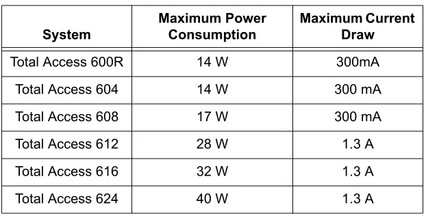
POWER REQUIREMENTS
The following power requirements apply:
3.
REVIEWING THE FRONT PANEL DESIGN
Total Access 600R
Figure 2 shows the Total Access 600R front panel.
Figure 1. Total Access 600R Front Panel Layout Table 1. AC Power Requirements
System
Maximum Power Consumption
Maximum Current Draw
Total Access 600R 14 W 300mA
Total Access 604 14 W 300mA
Total Access 608 17 W 300mA
Total Access 612 28 W 1.3A
Total Access 616 32 W 1.3A
Total Access 624 40 W 1.3A
Front Panel LEDs
The front panel provides five status LEDs to monitor operation and activity. Table 3 provides LED descriptions for Total Access 600R systems.
Total Access 604/608
The front panels of the Total Access 604/608 systems are identical. Figure 2 shows the Total Access 608 front panel as a representative of both models.
Figure 2. Total Access 604/608 Front Panel Layout Table 2. Total Access 600R Front Panel LEDs For these LEDs... This color light... Indicates that...
LAN TX/RX Off there is no data traffic on the LAN.
Green (blinking) there is data traffic on the LAN.
LAN LINK Off the physical link is down; there is no Ethernet connection.
Green (solid) there is link integrity on the LAN (physical link is up). WAN STAT Red (solid) the T1 is in red alarm or T1 sync loss has occurred.
Yellow (solid) the T1 is in yellow alarm. Green (solid) the unit is not in alarm.
WAN ERR Off the WAN link is up and error-free.
Red (solid) severe errors are present on the WAN link. Red (flashing) the T1 is down.
Yellow (solid) errors are present on the WAN link.
PWR Green (solid) power is supplied to the unit.
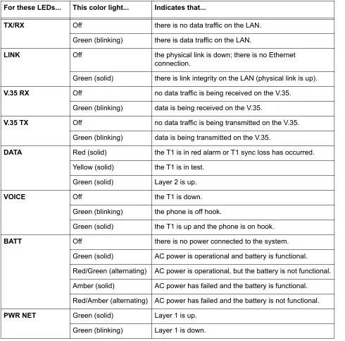
Front Panel LEDs
The front panel provides eight status LEDs to monitor operation and activity. The LED functionality varies based on product and software load (TDM versus ATM). Table 3 provides LED descriptions for Total Access 604/608 systems employing TDM software, and Table 4 on page 26 lists ATM software LED functionality.
Table 3. Total Access 604/608 TDM Front Panel LEDs For these LEDs... This color light... Indicates that...
TX/RX Off there is no data traffic on the LAN.
Green (blinking) there is data traffic on the LAN.
LINK Off the physical link is down; there is no Ethernet
connection.
Green (solid) there is link integrity on the LAN (physical link is up).
V.35 RX Off no data traffic is being received on the V.35.
Green (blinking) data is being received on the V.35.
V.35 TX Off no data traffic is being transmitted on the V.35. Green (blinking) data is being transmitted on the V.35.
DATA Red (solid) the T1 is in red alarm or T1 sync loss has occurred. Yellow (solid) the T1 is in test.
Green (solid) Layer 2 is up.
VOICE Off the T1 is down.
Green (blinking) the phone is off hook.
Green (solid) the T1 is up and the phone is on hook.
BATT Off there is no power connected to the system.
Green (solid) AC power is operational and battery is functional. Red/Green (alternating) AC power is operational, but the battery is not functional. Amber (solid) AC power has failed and the battery is functional. Red/Amber (alternating) AC power has failed and the battery is not functional.
PWR NET Green (solid) Layer 1 is up.
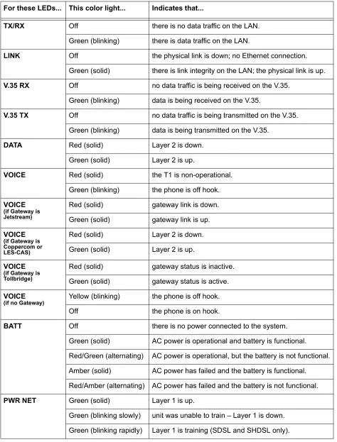
Table 4. Total Access 6XX ATM Front Panel LEDs For these LEDs... This color light... Indicates that...
TX/RX Off there is no data traffic on the LAN.
Green (blinking) there is data traffic on the LAN.
LINK Off the physical link is down; no Ethernet connection.
Green (solid) there is link integrity on the LAN; the physical link is up.
V.35 RX Off no data traffic is being received on the V.35.
Green (blinking) data is being received on the V.35.
V.35 TX Off no data traffic is being transmitted on the V.35. Green (blinking) data is being transmitted on the V.35.
DATA Red (solid) Layer 2 is down.
Green (solid) Layer 2 is up.
VOICE Red (solid) the T1 is non-operational.
Green (blinking) the phone is off hook. VOICE
(if Gateway is Jetstream)
Red (solid) gateway link is down. Green (solid) gateway link is up. VOICE
(if Gateway is Coppercom or LES-CAS)
Red (solid) Layer 2 is down. Green (solid) Layer 2 is up. VOICE
(if Gateway is Tollbridge)
Red (solid) gateway status is inactive. Green (solid) gateway status is active. VOICE
(if no Gateway) Yellow (blinking) the phone is off hook.
Off the phone is on hook.
BATT Off there is no power connected to the system.
Green (solid) AC power is operational and battery is functional. Red/Green (alternating) AC power is operational, but the battery is not functional. Amber (solid) AC power has failed and the battery is functional. Red/Amber (alternating) AC power has failed and the battery is not functional.
PWR NET Green (solid) Layer 1 is up.
Total Access 612/616/624
The front panels of the Total Access 612/616/624 systems are identical. Figure 3 shows the Total Access 612 front panel as a representative of all models.
Figure 3. Total Access 612/616/624 Front Panel Layout
Front Panel LEDs
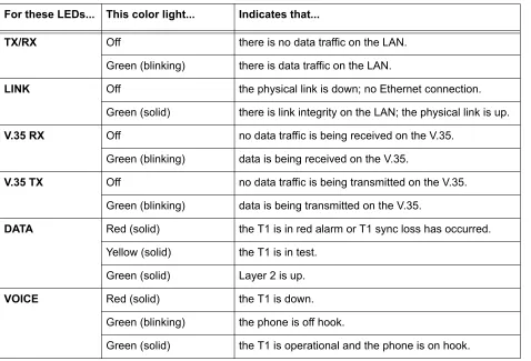
The front panel provides eight status LEDs to monitor operation and activity. The LED functionality varies based on product and software load (TDM versus ATM). Table 5 provides LED descriptions for Total Access 612/616/624 systems employing TDM software, and Table 4 on page 26 lists ATM software LED functionality.
Table 5. Total Access 612/616/624 TDM Front Panel LEDs For these LEDs... This color light... Indicates that...
TX/RX Off there is no data traffic on the LAN.
Green (blinking) there is data traffic on the LAN.
LINK Off the physical link is down; no Ethernet connection.
Green (solid) there is link integrity on the LAN; the physical link is up.
V.35 RX Off no data traffic is being received on the V.35.
Green (blinking) data is being received on the V.35.
V.35 TX Off no data traffic is being transmitted on the V.35. Green (blinking) data is being transmitted on the V.35.
DATA Red (solid) the T1 is in red alarm or T1 sync loss has occurred. Yellow (solid) the T1 is in test.
Green (solid) Layer 2 is up.
VOICE Red (solid) the T1 is down.
Green (blinking) the phone is off hook.
4.
REVIEWING THE REAR PANEL DESIGN
The Total Access 600R provides a NTWK connection (via an RJ-48 connector), a CRAFT interface (via an RJ-49 connector), a 10/100BASET interface (via an RJ-48 connector), and an AC PWR connection (via a 3-prong detachable power cord). In addition, systems can include the optional DSX-1 interface (via an RJ-48 connector). The Total Access 600R rear panel differs from the rest of the family in that it does not have a VOICE connection (50-pin amphenol connector). Figure 4 illustrates a standard Total Access 600R rear panel.
Figure 4. Total Access 600R Rear Panel
All other Total Access 600 Series systems contain the following rear panel interfaces regardless of the model: VOICE connection (via a 50-pin female amphenol connector), a NTWK connection (via an RJ-48 connector), a CRAFT interface (via an RJ-48 connector), a 10/100BASET interface (via an RJ-48 connector), a V.35 connection (via a 34-pin Winchester-style connector), a BATT connection (via a 3-pin modular plug), and an AC PWR connection (via a 3-prong detachable power cord). In addition, systems can include either a LIFE LINE analog interface (via an RJ-48 connector) or an optional DSX-1 interface (via an RJ-48 connector). Figure 5 on page 29 illustrates a standard Total Access 604/608, and Figure 6 and Figure 7 on page 29 illustrate the Total Access 604/608 rear panels with the LIFE LINE analog and
DSX-1 interfaces, respectively. Figures 8 through 10 on page 29 illustrate the Total Access 612/616/624 rear panels.
BATT Off there is no power connected to the system.
Green (solid) AC power is operational and battery is functional. Red/Green (alternating) AC power is operational, but the battery is not functional. Amber (solid) AC power has failed and the battery is functional. Red/Amber (alternating) AC power has failed and the battery is not functional.
PWR NET Green (solid) Layer 1 is up.
Figure 5. Total Access 604/608 Rear Panel
Figure 6. Total Access 604/608 Rear Panel with Optional Life Line POTS
Figure 7. Total Access 604/608 Rear Panel with Optional DSX-1 Interface
Figure 8. Total Access 612/616/624 Rear Panel
Figure 10. Total Access 612/616/624 Rear Panel with Optional DSX-1 Interface
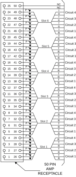
VOICE Connection
A single 50-pin female amphenol connector provides the interconnect wiring for the analog FXS and FXO (available as an option only on the Total Access 624) circuits. Figure 11 shows the VOICE connector pinout.
Figure 11. VOICE Connector Pin Assignments
NTWK Connection
The Total Access 600 Series NTWK connection is provided via an RJ-48 connector regardless of the
CRAFT Port
The CRAFT port (EIA-232) on the rear panel connects to a computer or modem and provides the following functions:
• Accepts EIA-232 input from a PC or a modem for controlling the Total Access 600 Series. • Baud rate is user-configurable.
• Acts as input for either VT100 or PC control.
• Acts as an interface for flash memory software downloads using XMODEM.
Table 7 shows the CRAFT port pinout.
A DB-9 to RJ-48 adapter is needed to connect a PC or VT100 terminal to the CRAFT port. This adapter is not part of the Total Access 600 Series shipment. You may obtain a free adapter (P/N 3196ADPT001) by contacting ADTRAN Technical Support or by adding the adapter to the system order. You can also build your own adapter by purchasing unassembled adapter kits from Black Box or Datacomm Warehouse (or other equivalent companies). The adapter pinout is shown in Table 8.
Table 6. NTWK Connection Pinout
PIN NAME DESCRIPTION
1 RX RING Receive data from the network
2 RX TIP Receive data from the network
3, 6-8 —––––– Unused
4 TX RING Transmit data toward the network
5 TX TIP Transmit data toward the network
Table 7. CRAFT Pinout
PIN NAME DESCRIPTION
1 GND Ground – connected to unit chassis
2 RTS Request to send – flow control
3 RXDATA Receive data
4 DTR Data terminal ready
5 TXDATA Transmit data
6 CD Carrier detect
7 —––––– Unused
8 CTS Clear to send - flow control
Table 8. DB-9 to RJ-48 Adapter Pinout
DB-9 RJ-48 DESCRIPTION
2 5 Transmit Data
3 3 Receive Data
Note: All other pins are unused.
Table 8. DB-9 to RJ-48 Adapter Pinout (Continued)
10/100BaseT Connection
The 10/100BASET port (RJ-48C) provides a 10/100BaseT Ethernet LAN connection for IP Routing, TFTP, SNMP, and Telnet connections. Table 9 shows the 10/100BaseT pinout.
V.35 Connection
The Total Access 600 Series system provides a single V.35 Winchester-style connection on the rear of the unit (as defined in Table 10).
Battery Backup Connection
An optional battery backup system is available for the Total Access 604/608 (P/N 1200641L1) and the Total Access 612/616/624 (P/N 1175044L1, 1175044L2, or 1175044L4). For more details on the battery backup system installation and operation, refer to the documentation available for your specific battery backup unit.
AC Power Connection
Each unit includes an auto ranging 90-250 VAC, 50/60 Hz power supply with a 3-prong removable cable. Connect the power supply to a standard 120 VAC, 60 Hz electrical outlet for proper operation.
Table 9. Ethernet Pinout
PIN NAME DESCRIPTION
1 TX1 Transmit Positive
2 TX2 Transmit Negative
3 RX1 Receive Positive
4, 5 —––––– Unused
6 RX2 Receive Negative
7, 8 —––––– Unused
Table 10. V.35 Winchester Pinout
PIN/CCIT DESCRIPTION PIN/CCIT DESCRIPTION
A/101 Protective ground (PG) V/115 RX clock (RC-A) to DTE
B/102 Signal ground (SG) X/115 RX clock (RC-B) to DTE
C/105 Request to send (RTS) from DTE P/103 Transmitted data (TD-A) from DTE D/106 Clear to send (CTS) to DTE S/103 Transmitted data (TD-B) to DTE E/107 Data set ready (DSR) to DTE Y/114 TX clock (TC-A) to DTE
E/109 Data carrier detect AA/114 TX clock (TC-B) to DTE
H/— Data terminal ready (DTR) from DTE U/113 External TX clock (ETC-A) from DTE
J/— Ring indicator (RI) W/113 External TX clock (ETC-B) from DTE
Life Line Analog Connection
The LIFE LINE analog connection provides assured voice for port 1. If the unit loses power or goes into alarm, the network voice service is inhibited and the on-board relay opens. The first port of the voice connector is provided with analog voice from the LIFE LINE analog connection. A regular POTS line must be plugged into the LIFE LINE port. Table 11 provides the LIFE LINE port pinout.
DSX-1 Interface
Table 12 provides the DSX-1 port pinout.
The LIFE LINE analog connection is only available on Total Access 600 Series xDSL models.
Table 11. LIFE LINE Connection Pinout
PIN DESCRIPTION
1,2 Unused
3 Life Line Ring
4 Life Line Tip
5,6 Unused
The DSX-1 interface is optional and must be requested at the time of order placement. Total Access 600 Series systems without the DSX-1 interface are not field-upgradeable to add DSX-1 access.
Table 12. DSX-1 Connection Pinout
PIN NAME DESCRIPTION
1 TX RING Transmit data toward the network (RING)
2 TX TIP Transmit data toward the network (TIP)
3, 6-8 —––––– Unused
4 RX RING Receive data from the network (RING)
5.
AT-A-GLANCE SPECIFICATIONS
Table 13 lists the unit specifications.
Table 13. Specifications
Application Feature Specification
T1 Network Interface
Physical Interface RJ-48C
Line Rate 1.544 Mbps +/- 75 bps
Framing D4 (SF)/ESF
AT&T 54016 ANSI T1.403
Line Code AMI/B8ZS
ADSL Network Interface (ITU G.992.1)
Throughput Up to 8 Mbps downstream
Up to 1 Mbps upstream
Interoperability Interoperate with G.992.1 compliant DSLAMs G.SHDSL Network Interface (ITU G.991.2)
Line Rate 192 kbps to 2.3 Mbps
SDSL Network Interface (2B1Q Conexant-based)
Line Rate 160 kbps to 2.3 Mbps
Training Conexant Autobaud capable
ATM Support
Voice Codes PCM (G.711)
32K ADPCM (G.726) PVC Capability 6 PVCs (1 voice, 5 data)
Echo Cancellation G.165/G.168 Echo Cancellation, 8 ms echo tail
QoS Support VBR-rt (voice)
UBR (data)
Specifications AAL2 (voice)
AAL5 (data, voice)
RFC 1483 (multiprotocol over ATM) RFC 2364 (PPPoA)
Frame Relay Support
Specifications FRF.5
Analog Ports
Number of FXS Ports 4 ports for Total Access 604 8 ports for Total Access 608 12 ports for Total Access 612 16 ports for Total Access 616 24 ports for Total Access 624
Modes FXS Loop Start
FXS Ground Start TR08 Single TR08 UVG DP0
Tandem (E&M)
Ringing Balanced ringing, 5 REN per port not to exceed 35 REN
Ring Voltage Fixed 70 VACrms with 20 VDC offset Routing (Ethernet)
Specifications IEEE 802.3
IP Support TCP, RIP V1, RIP V2, UDP, ICMP, ARP, UDP Relay, SYSLOG
PPP Support LCP, IPCP, BCP
DHCP DHCP Server to LAN
DHCP from network Management
CRAFT Interface EIA 232, Physical RJ-48C Ethernet 10/100BaseT
Interface
SNMP V1 support
• 604/608 ATM units running D.01.36 firmware or previous
• 612/616/624 ATM units running D.01.30 firmware or previous
SNMP V2 support
• TDM units running A.04 firmware or later Full menu-driven Telnet access
Software download via TFTP
Support for VoDSL gateway management systems and firmware download
Table 13. Specifications (Continued)
This section provides shipment contents list, grounding instructions, mounting options, and specifics of supplying power to the unit.
C
ONTENTSTools Required . . . 36 Unpack and Inspect the SYSTEM . . . . 36 Contents of ADTRAN Shipments . . . 37 Grounding Instructions . . . 37 Mounting Options . . . 38 Wallmounting the Unit . . . 38 Rackmounting the Total Access 612/616/624 . . . 40 Supplying Power to the Unit . . . 40 AC Powered Systems . . . 40
F
IGURES1.
INTRODUCTION
This section discusses Total Access 600 Series installation.
2.
TOOLS REQUIRED
The tools required for wallmount installation of the unit are: • Four #8 x 3/4 inch pan-head wood screws
• Drill and drill bit set
• Flat head screwdriver (medium)
• Two Phillips head screwdrivers (small/medium) • Wire-wrap gun (optional)
• 25-pair male amphenol cable (customer connection) • Selected punch-down block and tool
3.
UNPACK AND INSPECT THE SYSTEM
Each unit is shipped in its own cardboard shipping carton. Open each carton carefully and avoid deep penetration into the carton with sharp objects.
After unpacking the unit, inspect it for possible shipping damage. If the equipment has been damaged in transit, immediately file a claim with the carrier, and then contact ADTRAN Customer Service (see Customer Service, Product Support Information, and Training in the front of this manual).
To prevent electrical shock, do not install equipment in a wet location or during a lightning storm.
During installation, power should be the last connection made.
Contents of ADTRAN Shipments
Your ADTRAN shipment includes the following items:
• The Total Access 6XX unit with attached wallmount brackets • The Total Access 600 SeriesSystem CD – ADTRAN P/N 3253052 • Hardware revision notice card – ADTRAN P/N 61200624L1-17 • Mounting instructions – ADTRAN P/N 61200624L1-19
• RJ-45 to RJ-45 8-pin cable (6 ft) –ADTRAN P/N 3127004 • Cable tie (for securing attached cables) – ADTRAN P/N 3292032 • Four rubber feet (for table top installations) – ADTRAN P/N 3270BF003 • 3-prong, detachable power cord – ADTRAN P/N 3127009
4.
GROUNDING INSTRUCTIONS
To following paragraphs provide grounding instruction information from the Underwriters’ Laboratory UL60950 Standard for Safety of Information Technology Equipment Including Electrical Business Equipment, with revisions dated March 15, 2002.
An equipment grounding conductor that is not smaller in size than the ungrounded branch-circuit supply conductors is to be installed as part of the circuit that supplies the product or system. Bare, covered, or insulated grounding conductors are acceptable. Individually covered or insulated equipment grounding conductors shall have a continuous outer finish that is either green, or green with one or more yellow stripes. The equipment grounding conductor is to be connected to ground at the service equipment.
The attachment-plug receptacles in the vicinity of the product or system are all to be of a grounding type, and the equipment grounding conductors serving these receptacles are to be connected to earth ground at the service equipment.
A supplementary equipment grounding conductor shall be installed between the product or system and ground that is in addition to the equipment grounding conductor in the power supply cord.
The supplementary equipment grounding conductor shall not be smaller in size than the ungrounded branch-circuit supply conductors. The supplementary equipment grounding conductor shall be connected to the product at the terminal provided, and shall be connected to ground in a manner that will retain the ground connection when the product is unplugged from the receptacle. The connection to ground of the supplementary equipment grounding conductor shall be in compliance with the rules for terminating bonding jumpers at Part K or Article 250 of the National Electrical Code, ANSI/NFPA 70. Termination of the supplementary equipment grounding conductor is permitted to be made to building steel, to a metal electrical raceway system, or to any grounded item that is permanently and reliably connected to the electrical service equipment ground.
The supplemental grounding conductor shall be connected to the equipment using a number 8 ring terminal and should be fastened to the grounding lug provided on the rear panel of the equipment. The ring terminal should be installed using the appropriate crimping tool (AMP P/N 59250 T-EAD Crimping Tool or
5.
MOUNTING OPTIONS
All units may be wallmounted or installed in a table-top application. In addition, the Total Access 612/616/624 units are available for 19- or 23-inch rackmount installations. Wallmount brackets are included with the unit and are already attached. For a rackmount installation, optional rackmount brackets must be purchased (19” – P/N 1200627L1, 23” – P/N 1200627L2).
Wallmounting the Unit
Tools Needed
The unit mounts and connects with standard fasteners and hand tools: • Four #8 x 3/4-inch pan-head wood screws
• Drill and drill bit set
• Flat head screwdriver (medium)
• Two Phillips head screwdrivers (small/medium) • Wire-wrap gun (optional)
• 25-pair male amphenol cable (customer connection) • Selected punch-down block and tool
Follow these steps to wallmount the unit:
Be careful not to upset the stability of the equipment mounting rack when installing this product.
Wallmount Installation
Step Action
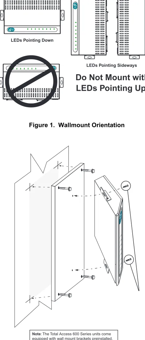
1. Decide on a location for the unit. Keep in mind that the unit needs to be mounted at or below eye-level so that the LEDs are viewable.
IMPORTANT! Mount the chassis with LEDs facing to the side or down as shown in Figure 1 on page 39 (not facing up).
Refer to Figure 2 on page 39 for a wallmount illustration.
2. Prepare the mounting surface by attaching a board (typically plywood, 3/4” to 1” thick) to a wall stud.
IMPORTANT! Mounting to a stud ensures stability. Using sheetrock anchors may not provide sufficient long-term stability.
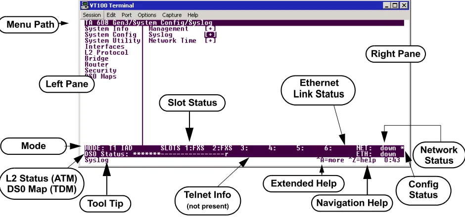
3. Have someone else hold the unit in position as you install two #6 to #10 (1 1/2” or greater in length) wood screws through the unit’s brackets and into the mounted board.
Figure 1. Wallmount Orientation
Figure 2. Wallmounting the Unit
Rackmounting the Total Access 612/616/624
Tools Needed
The Total Access 612/616/624 mount and connect with standard fasteners and hand tools: • Rackmount brackets (19”–P/N 1200627L1 or 23”–P/N 1200627L2)
• Flat head screwdriver (medium)
• Two Phillips head screwdrivers (small/medium) • Wire-wrap gun (optional)
• 25-pair male amphenol cable (customer connection) • Selected punch-down block and tool
Follow these steps to rackmount the Total Access 612/616/624:
6.
SUPPLYING POWER TO THE UNIT
The Total Access 600 Series is not offered in DC powered versions. However, optional DC battery backup systems are available for the Total Access 604/608 (P/N 1200641L1) and Total Access 612/616/624 (P/N 1175044L1, 2, or 4) systems.
AC Powered Systems
The AC powered unit comes equipped with a 3-prong, detachable power cord for connecting to a properly grounded power receptacle. As shipped, the unit is set to factory default conditions. After installing the unit it is ready for power-up. To apply power to the unit, ensure that it is properly connected to an appropriate power source.
Rackmount Installation
Step Action
1. Remove the wallmount brackets. (The Total Access 612/616/624 ships with wallmount brackets attached.) Attach the mounting brackets to the side of the unit.
To avoid damaging the unit, use only the screws included in the mounting bracket shipment when attaching mounting ears to the chassis.
2. Position the Total Access 612/616/624 in a stationary equipment rack. This unit takes up 1 RU of space. To allow proper grounding, scrape the paint from the rack around the mounting holes where the Total Access 612/616/624 will be positioned.
3. Have someone else hold the unit in position as you install two mounting bolts through the unit’s brackets and into the equipment rack using a #2 Phillip’s screwdriver. 4. Proceed to the steps given in Supplying Power to the Unit.
• This unit shall be installed in accordance with Article 400 and 364.8 of the NEC NFPA 70 when installed outside of a Restricted Access Location (i.e., central office, behind a locked door, service personnel only area).
This section of ADTRAN’s Total Access 600 Series System Manual is designed for use by network administrators and others who will configure and provision the system. It contains information about navigating the VT100 user interface, configuration information, and menu descriptions.
C
ONTENTSF
IGURESFigure 1. Top-Level Terminal Menu Window . . . 43 Figure 2. Alternate Menu View . . . 44 Figure 3. System Info Menu . . . 49 Figure 4. System Config Menu . . . 51 Figure 5. System Utility Menu . . . 64 Figure 6. Interfaces Menus . . . 71 Figure 7. L2 Protocol (T1 TDM) Menu. . . 89 Figure 8. L2 Protocol (SDSL ATM) Menu . . . 100 Figure 9. Bridge Menu. . . 117 Figure 10. Router Menu . . . 119 Figure 11. Security Menu . . . 141 Figure 12. DS0 Maps Menu . . . 149 Figure 7. Application Diagram . . . 169 Figure 10. Application Diagram . . . 174
T
ABLES1.
NAVIGATING THE TERMINAL MENU
To access the terminal menus and management features of the Total Access 6XX, connect the unit to a VT100 terminal (or VT100 terminal emulator) via the CRAFT interface on the rear panel. Configure the terminal settings for 9600 data rate, no parity, 8 data bits, 1 stop bit, and no flow control.
After connecting to the unit and beginning a terminal session, a login screen appears. There is no default password for the Total Access 6XX; press <ENTER> to access the terminal menus. (Refer to DLP-2, Logging in to the System for detailed instructions.)
Terminal Menu Window
After logging in, all menu items and data fields are displayed in the terminal menu window (see Figure 1), through which you have complete control of the unit.
Figure 1. Top-Level Terminal Menu Window
Menu Path
The first line of the terminal menu window (the menu path) shows the session’s current position (path) in the menu structure. For example, Figure 1 shows the top-level menu with the cursor on the SYSTEM CONFIG submenu; therefore, the menu path reads TA6XX IAD/SYSTEM CONFIG.
Window Panes
When you first start a terminal menu session, the terminal menu window is divided into left and right panes. The left pane shows the list of available submenus, while the right pane shows the contents of the currently selected submenu.
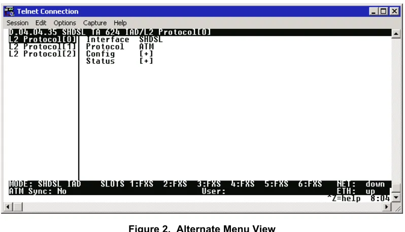
You can view the terminal windows in two ways: with fields and submenus displaying horizontally across the right pane, or with fields and submenus displaying vertically down the right pane. Viewing submenus vertically rather than horizontally allows you to see information at a glance rather than scrolling horizontally across the window. To change the view, move your cursor to an index number and press <ENTER>. Figure 2 on page 44 shows this alternate view. Fields and submenu names may vary slightly in this view.
Left Pane Menu Path
Right Pane
Tool Tip Navigation Help
Extended Help Slot Status
Network Status
Telnet Info Mode
Ethernet
Link Status
L2 Status (ATM)
DS0 Map (TDM) Config
Status
Figure 2. Alternate Menu View Window Pane Navigation
Use the following chart to assist you in moving between and within the two window panes.
Right Window Pane Notation
The right window pane shows the contents of the currently selected menu. These contents include both submenu items and data fields. Some submenus contain additional submenus and some data fields contain additional data fields. The following chart explains the notation used to identify these additional items.
To do this... Press this key...
Move from left pane to right pane Tab Enter Right arrow Move from right pane to left pane Tab
Escape Left arrow Backspace Move within each pane Up arrow
Down arrow Left arrow Right arrow
This notation... Means that...
[+] more items are available when selected.
[DATA] more items are available when selected.
Additional Terminal Menu Window Features
• Mode – displays the network interface mode of the unit (for example, T1 IAD, SHDSL IAD, SDSL IAD, ADSL IAD)
• L2 Status – displays the current status of the L2 protocol (ATM sync is either up or down) – ATM Only • DS0 Mapping – displays the current mapping of DS0s in the system. DS0s mapped to the router
display r, unmapped DS0s display –, and all other DS0s display *. • Tool Tip – provides a brief description of the currently selected mode.
• Slot Status – displays type of module installed in each slot. No entry will appear for slots not containing a module.
• Telnet Info – displays the user name when connected via Telnet. This information is not displayed when connecting to the system via the CRAFT interface.
• Ethernet Link Status – displays the current status of the integrated Ethernet interface (located on the rear of the chassis).
• Extended Help – displays information about selected commands <CTRL+A>.
• Navigation Help – lists characters used for navigating the terminal menu and session management <CTRL+Z>.
• Config Status – displays * when current configuration contains changes that have not been saved to flash memory. Save changes by backing out to the main menu, or press <CTRL + W> to force a manual save.
Navigating using the Keyboard Keys
You can use various keystrokes to move through the terminal menu, to manage a terminal menu session, and to configure the system. Press <CTRL+Z > to activate a pop-up screen listing the navigation keystrokes.
Moving through the Menus
To do this... Press this key...
Return to the home screen H
Jump between two menu items
Press <J> while the cursor is located on a menu item, and you jump back to the main screen.
Go to another menu item, press <J>, and you jump back to the screen that was displayed the first time you pressed <J>.
Press <J> anytime you want to jump between these items.
J
Select items Arrows
Edit a selected menu item Enter
Cancel an edit Escape
Close pop-up help screen Escape
Move between the left and right panes Tab
Arrows
Session Management Keystrokes
Configuration Keystrokes
Move to the bottom of a screen Z
Ascend one menu level Backspace
Jump to terminal mode CTRL+T
Jump to NAT menu CTRL+N
To do this... Press this key...
Log out of a session CTRL+L
Refresh the screen
To save time, only the portion of the screen that has changed is refreshed. This option should only be necessary if the display picks up incorrect characters caused by disconnecting and reconnecting the terminal session.
CTRL+R
To do this... Press this key...
Restore factory default settings
This setting restores the factory defaults based on the location of the cursor. If the cursor is on an interface line (in the INTERFACES menu), then only the selected
interface is updated to factory defaults.
F
Copy selected items to the clipboard
The amount of information you can copy depends on the cursor location when you press <C>:
If the cursor is over an editable field, only that item is copied.
If the cursor is over the index number of a list, then all of the items in the row of the list are copied. For example, if the cursor is over the selection # field in the INTERFACES screen, all of the information associated with the interface is
copied.
C
Paste the item stored in the clipboard, if the information is compatible You must confirm all pastes — except those to a single editable field.
P
Increment the value of certain types of fields by one when you paste information into those fields
>
Decrement the value of certain types of fields by one when you paste information into those fields
<
Save the current configuration immediately to flash memory CTRL+W Insert a new list item
For example, add a new item to the TELNET USER connection list by pressing <I>
I
Getting Help
The bottom line of the terminal menu window contains context-sensitive help information. When the cursor is positioned over a set of configuration items, a help message displays (when available) providing a description of the item. When more detailed help is available for a particular item, ^A displays at the bottom of the window. At this point, pressing <CTRL+A> displays a pop-up help screen with information about the item.
Press <CTRL+Z> to activate a help screen that displays the available keystrokes you can use to navigate the main menu system. Press <Exit> to remove these help screens.
2.
MAIN MENU AND SYSTEM CONTROL
Selecting the Appropriate Menu
The main menu system is the access point to all other operations. Each menu item has several functions and submenus that identify and provide access to specific operations and parameters. Use the following chart to help select the appropriate menu.
Delete a list item
For example, delete an item from the TELNET USER connection list by pressing
<D> while the index number is active.
D
To do this... Go to this menu...
Review and monitor general system information for the Total Access 6XX SYSTEM INFO
Set up the operational configuration for the Total Access 6XX SYSTEM CONFIG
Upgrade firmware, perform config transfers, ping, and access terminal mode SYSTEM UTILITY
Review and configure settings for all interfaces (including installed modules) INTERFACES
Configures the Layer 2 protocol for the various interfaces (T1, Ethernet, etc.) and provides all applicable L2 status information
L2 PROTOCOL
Configure the bridging parameters and view applicable bridging statistics BRIDGE
Define, configure, and monitor all Total Access 6XX Router functions ROUTER
Configure security filters for L2 traffic and define RADIUS server parameters SECURITY
Map data and voice ports (from integrated interfaces as well as installed modules) to network time slots
DS0 MAPS
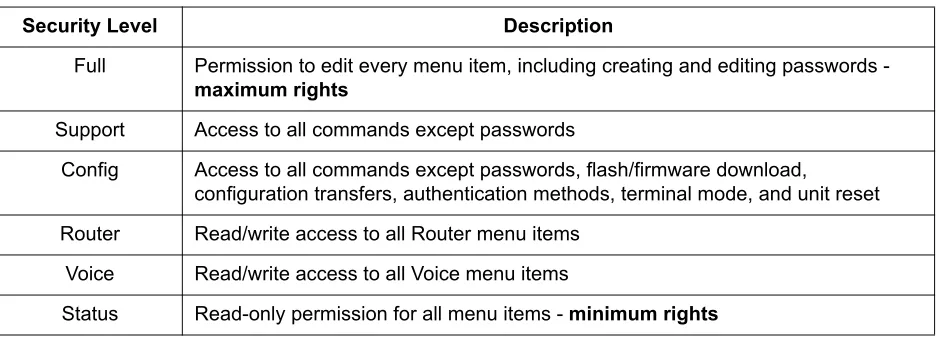
Security Levels
To edit main menu system items, you must have a password and the appropriate security level. Table 1 describes the security levels.
3.
MENU DESCRIPTIONS
The remainder of this section describes Total Access 6XX menu and submenu options.
Password security levels only apply to Telnet connections. Connecting to the system through the rear CRAFT interface automatically provides maximum rights.
Table 1. Password Security Level
Security Level Description
Full Permission to edit every menu item, including creating and editing passwords - maximum rights
Support Access to all commands except passwords
Config Access to all commands except passwords, flash/firmware download, configuration transfers, authentication methods, terminal mode, and unit reset Router Read/write access to all Router menu items
Voice Read/write access to all Voice menu items
Status Read-only permission for all menu items - minimum rights
To help you follow the terminal menu hierarchy, the following notations are used:
S
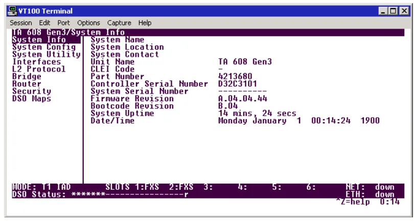
YSTEMI
NFOThe SYSTEM INFO menu provides basic information about the unit as well as data fields for editing information. Figure 3 displays the submenus that are available when you select this menu item.
0
Figure 3. System Info Menu
S
YSTEMI
NFO> S
YSTEMN
AMEProvides a user-configurable text string for the name of the unit. This name can help you distinguish between different installations. You can enter up to 127 alpha-numeric characters in this field, including spaces and special characters (such as an underscore). This name will appear on the top line of all screens.
S
YSTEMI
NFO> S
YSTEML
OCATIONProvides a user-configurable text string for the location of the unit. This field is to help you keep track of the actual physical location of the unit. You can enter up to 127 alphanumeric characters in this field, including spaces and special characters (such as an underscore).
S
YSTEMI
NFO> S
YSTEMC
ONTACTProvides a user-configurable text string for a contact name. You can use this field to enter the name, phone number, or E-mail address of a person responsible for the unit. You can enter up to 127 alpha-numeric characters in this field, including spaces and special characters (such as an underscore).
S
YSTEMI
NFO> U
NITN
AME(Read only) Displays a product-specific name for the unit (such as TA 616, TA 604, etc).
S
YSTEMI
NFO> CLEI C
ODES
YSTEMI
NFO> P
ARTN
UMBER(Read only) Displays the ADTRAN-specific part number for the unit.
S
YSTEMI
NFO> C
ONTROLLERS
ERIALN
UMBER(Read only) Displays the ADTRAN-specific part number for the chassis hardware. The serial number of the unit will automatically display in this field. This serial number matches the serial number located on the bottom of the unit’s chassis.
S
YSTEMI
NFO> S
YSTEMS
ERIALN
UMBER(Read only) Displays the serial number for the entire system configuration including specific network interface, FXS specifics, and specialized software, as well as the base chassis. This serial number must be programmed at ADTRAN and will display dashes (----) for any unit manufactured prior to this serial number addition.
S
YSTEMI
NFO> F
IRMWARER
EVISION(Read only) Displays the current firmware revision level of the unit.
S
YSTEMI
NFO> B
OOTCODER
EVISION(Read only) Displays the current bootcode revision.
S
YSTEMI
NFO> S
YSTEMU
PTIMEDisplays the length of time the unit has been running. Each time you reset the system, this value resets to 0 days, 0 hours, 0 min and 0 secs.
S
YSTEMI
NFO> D
ATE/T
IMEDisplays the current date and time, including seconds. To edit this field, place the cursor on the field and press <ENTER>. Then, enter the time in a 24-hour format (such as 23:00:00 for 11:00 pm), and the date in mm-dd-yyyy format (for example, 05-23-2004). Press <ENTER> when you are finished to accept the change.
S
YSTEMC
ONFIGSet up the unit’s operational configuration from the SYSTEM CONFIG menu. Figure 4 shows the items included in this menu.
Figure 4. System Config Menu
S
YSTEMC
ONFIG> M
ANAGEMENTSet up the CRAFT port, TELNET ACCESS, SNMP MANAGEMENT, and FDL MANAGEMENT from this menu.
S
YSTEMC
ONFIG> M
ANAGEMENT> CRAFT P
ORTSet up the CRAFT port parameters from this menu. The unit’s VT100 CRAFT port can be accessed via an RJ-48 connector located on the rear of the unit.
S
YSTEMC
ONFIG> M
ANAGEMENT> CRAFT P
ORT> P
ASSWORDP
ROTECTWh