Article
Real-Time Lossless Compression Algorithm for
Ultrasound Data Using BL Universal Code
Jung Hoon Kim1, Sunmi Yeo2, Jong Won Kim3, Kyeongsoon Kim4, Tai-kyong Song2, Changhan Yoon5 and Joohon Sung1
1 Graduate School of Public Health, Seoul National University, Seoul 08826, Korea; [email protected], [email protected]
2 Department of Electronic Engineering, Sogang University, Seoul 04107, Korea; [email protected], [email protected]
3 Department of Healthcare IT, Inje University Kimhae, 50834, Korea; [email protected] 4 Department of Pharmaceutical Engineering, Inje University Kimhae, 50834, Korea; [email protected] 5 Department of Biomedical Engineering, Inje University Kimhae, 50834, Korea; [email protected]
* Correspondence: [email protected]; Tel.: +82-55-320-3301
Abstract: Software-based ultrasound imaging systems provide high flexibility that allows easy and fast adoption of newly developed algorithms. However, the extremely high data rate required for data transfer from sensors (e.g., transducers) to the ultrasound imaging systems is a major bottleneck in the software-based architecture, especially in the context of real-time imaging. To overcome this limitation, in this paper, we present a Binary cLuster (BL) code, which yields an improved compression ratio compared to the exponential Golomb code. Owing to the real-time encoding/decoding featureswithout overheads, the universal code is a good solution to reduce the data transfer rate for software-based ultrasound imaging. The performance of the proposed method was evaluated using in vitro and in vivo data sets. It was demonstrated that the BL-beta code has a good stable lossless compression performance of 20 ~ 30% while requiring no auxiliary memory or storage.
Keywords: Medical ultrasound; Lossless compression; Universal code; Run-length encoding
1. Introduction
Conventional ultrasound imaging systems are based on special-purpose hardware such as application-specific integrated circuits (ASICs) and field-programmable gate arrays (FPGAs) [1-3]. These fixed-function chips can meet high data transfer rates and computation requirements for real-time ultrasound imaging. However, the low flexibility of hardware-based ultrasound imaging systems often requires considerable time and expense in deploying new features and applications. To mitigate the problem, several ultrasound imaging platforms have been developed using programmable processors with high flexibility, which enable rapid prototyping and allow new applications to run on the same imaging platforms [4, 5]. These ultrasound imaging systems generally employ a PC as the imaging host and graphic processing units (GPUs) or digital signal processors (DSPs) to support the higher computational complexity [6, 7].
Although the high computational demands can be alleviated by using GPUs, the large amount of data transfer poses an additional problem that hinders the practical implementation of software-based architecture in ultrasound imaging systems. For example, ultrasound imaging systems with 128 channels, a sampling rate of 40 MHz, and a 12-bit analog-to-digital convertor’s (ADC) resolution require a data transfer rate of 10 GB/s. A commercially available ultrasound imaging system (i.e., Vantage, Verasonics Inc., Kirkland, WA) can support a data transfer rate up to 6.6 GB/s via eight PCI express lanes [8]. Although the high data transfer rate can be supported by using more and fast PCI express lanes, it would increase the cost and power consumption; hence, this approach is only
suitable for high-end ultrasound imaging systems. To adopt a software-based architecture in low-cost ultrasound imaging systems such as portable and hand-held ultrasound imaging systems, the data transfer should be achieved by using a popular interface such as a Universal Serial Bus (USB) [3, 9].
Data compression has been investigated to reduce the amount of ultrasound data in software-based ultrasound imaging systems [10-12]. The MPEG compression method was utilized to compress radio-frequency (RF) data. However, it requires high computation and memory resources for coding and decoding [11]. More recently, a lossless compression method for improving the performance of GPU-based beamformers was proposed [12]. However, this method needs additional memory (e.g., address memory) for decoding, and hence the compressed data can be larger than the original data because of the additional addresses. In addition, this method groups several data into a batch for compression; consequently, it does not permit independent data extraction.
A universal code is a prefix code that maps integers onto binary codewords and is widely used in data compression [13]. The universal code is a lossless data compression method, and the binary codewords are uniquely decodable for random integers. The main advantage of the universal code is that it can be easily implemented through simple calculations. However, the compressed codes generated from an equivalent number of symbols are not optimal compared to ones generated by the dictionary method such as Huffman and Lempel–Ziv–Welch (LZW) codes [14]. To address this limitation, the authors have proposed a new universal code, called Binary-cLuster (BL) code, by modifying the conventional exponential Golomb code [15]. The proposed BL code shows better compression performances, especially for data sets with large integers. For example, the BL code encodes the integer 1,000,000 as a 26-bit binary number (i.e., 11100011110100001001000001), while Elias Gamma, Fibonacci and Elias Delta codes encode the same integer as a 39-bit, 30-bit and 28-bit binary number, respectively. In addition, the BL code can compress any sequence of integers in real time without any overhead data in encoding and decoding.
In this paper, we propose a BL code-based ultrasound signal compression method for real-time software-based portable medical ultrasound imaging systems. It was shown that the BL code outperforms the exponential Golomb code in terms of the compression ratio for both in vitro and in vivo ultrasound data sets. Compression ratios of the proposed method for various signals in the signal processing chain of the ultrasound imaging system, such as pre-beamformed, beamformed and baseband inphase/quadrature (IQ) data, were also evaluated.
2. Method
2.1. Prefix of BL code
For random binary data, the datum in front of “10” is separated when “10” is encountered either from the top (left) to the bottom (right) direction or in the opposite direction. For example,
“1011101010010101111101001...” can be separated into “1011/10/10/100/10/101111/10/1001.” These
separated binary numbers are herein referred to as binary clusters. By doing so, binary clusters can be created from any binary data that starts with “10” [16]. Table 1 shows the first ten cluster patterns. The sequential index corresponding to each binary cluster will be referred toas code-num. Note that the binary cluster must start with the seed binary cluster “10”. As the code-num increases, each bit of
the binary cluster holding “0” is replaced by “1”, one at a time, from bottom to top. When all “0” bits are flipped to “1”except for that in the seed binary cluster “10”, the bit length of the binary cluster is increased by adding “0” on the right, and then every“1” is replaced by “0” except for the most significant bit (MSB). By doing so, each code-num is allocated to a distinct binary cluster and can be used for a universal code.
𝐾(𝐾 − 1)/2 < 𝑀 ≤ 𝐾(𝐾 − 1)/2, which is equivalent to (−1 + √1 + 8𝑀)/2 ≤ 𝐾 < (1 + √1 + 8𝑀)/2. Hence, K is obtained from a code-num M as
𝐾 = [1+√1+8𝑀
2 ], (1)
where [x] returns the largest integer that is smaller than x. Now, let us introduce X, which is given by
𝑋 = 𝑀 −𝐾(𝐾−1)
2 . (2)
With K and X, the binary code for each M is encoded as a bit stream composed of the MSB (=”1”)
followed by K-(X-1) zeros and X-1 ones. For example, when M=10, K and X are 1 and 4 according to Eqs. (1) and (2), respectively. Thus, the corresponding binary cluster is represented by “10111” as it
has one (=4-(4-1)) “0” bit and three (=4-1) “1” bits, which is identical to the binary cluster for M=10 in Table 1.
The unary code is used for a prefix of the exponential Golomb code that is adopted for video compression codecs, e.g., H.264 [13]. In the unary code, a code-num N is encoded as N-1 “0”s followed by one “1”. For example, the unary codes for M = 1, 2, 3, and 4 are “1”, “01”, “001” and “0001”, respectively. The unary code is a simple and fast coding method, but its bit length increases with the integer value to be encoded. For the code-num 10, the unary code has a bit length of 10. However, the bit length of encoded code by the proposed method is 5 (i.e., 10111), yielding 50% compression efficiency in the prefix encoding. This efficiency becomes higher for a larger code-num.
2.2. Proposed BL code encoding
In the exponential Golomb code, a binary code that directly converts a decimal to binary numbers with variable-width strings is concatenated as a suffix code. The exponential Golomb code using the unary code is an optimal code when integers follow a geometric distribution. Thus, it is useful for image/video compression. However, as the amplitude of the ultrasound signal follows the Rayleigh distribution [17], the efficiency of compression would be lower if the exponential Golomb
TABLE 1. BINARY CLUSTER PATTERNS FROM THE PROPOSED AND UNARY CODE METHODS
code_num (M) Binary cluster
Reversed form of
binary cluster
(Prefix)
Group index (K)
(bit length of
binary cluster - 1)
1 10 01 1
2 100 001 2
3 101 101 2
4 1000 0001 3
5 1001 1001 3
6 1011 1101 3
7 10000 00001 4
8 10001 10001 4
9 10011 11001 4
10 10111 11101 4
code is used. To overcome this limitation, our BL code uses the proposed prefix and the binary coded decimal with increasing bit lengths as the suffix code as shown in Table 2. Note that the reversed binary cluster is used as a prefix to preserve the unique decodability. Otherwise, the same bit stream for different integer Z can be obtained with a non-reversed form. For example, assuming an encoded bit stream “101110”, the prefix of encoded code can be “101”, “1011”, and “10111” with a non-reversed form. However, if we use a reversed form, it can be readily found that the prefix is “101”.
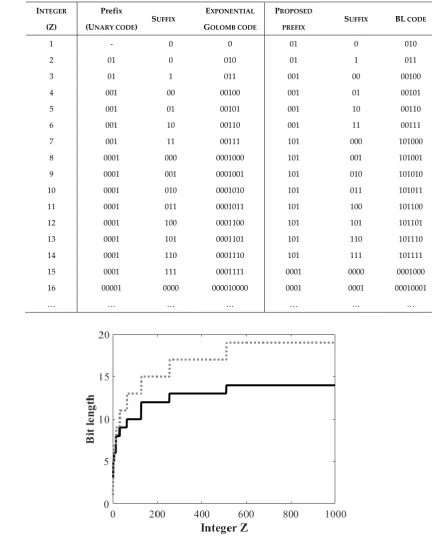
Table 2 lists some examples of the conventional Golomb and BL codes. In the proposed method, the
TABLE 2.ENCODED CODES USING THE CONVENTIONAL GOLOMB AND BL CODES
INTEGER
(Z)
Prefix
(UNARY CODE) SUFFIX
EXPONENTIAL
GOLOMB CODE
PROPOSED PREFIX
SUFFIX BL CODE
1 - 0 0 01 0 010
2 01 0 010 01 1 011
3 01 1 011 001 00 00100
4 001 00 00100 001 01 00101
5 001 01 00101 001 10 00110
6 001 10 00110 001 11 00111
7 001 11 00111 101 000 101000
8 0001 000 0001000 101 001 101001
9 0001 001 0001001 101 010 101010
10 0001 010 0001010 101 011 101011
11 0001 011 0001011 101 100 101100
12 0001 100 0001100 101 101 101101
13 0001 101 0001101 101 110 101110
14 0001 110 0001110 101 111 101111
15 0001 111 0001111 0001 0000 0001000
16 00001 0000 000010000 0001 0001 00010001
… … … …
prefix and the suffix parts can be distinguished with “01” (i.e., the reversed form of the seed binary cluster in Table 1).
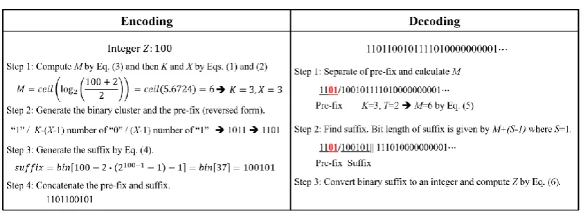
The BL code encodes an integer Z as follows. Empirically, we found that the code-num M of prefix can be obtained from a random integer Z as
𝑀 = 𝑐𝑒𝑖𝑙(log2((𝑍 + 2𝑆)/2𝑆)), (3)
where ceil(·) is the ceiling function and S is an external integer parameter satisfying S ≥ 1. The number of bits allocated for the suffix code can be adjusted depending on S. In this study, we use the BL code with S=1 for encoding. With M by Eq. (3), K and Xcan be obtained from Eqs. (1) and (2), and then, the prefix for BL code is generated as described above in Section 2.1. Finally, the suffix of the proposed code, which uses the binary coded decimal (see Table 2), is obtained as
𝑠𝑢𝑓𝑓𝑖𝑥 = 𝑏𝑖𝑛[𝑍 − 2𝑆× (2𝑀−1− 1) − 1], (4)
where bin[·] represents the decimal-to-binary converter. It is worth noting that from Eqs. (3) and (4), the bit length of the suffix of the proposed BL code is given by M+(S-1).
Figure 1 shows the bit lengths of encoded integers Z from 1 to 1,000 by using the proposed and exponential Golomb code methods. Note that the bit lengths of encoded integers vary as a function of the integer, which lead to a reduced data rate compared to the fixed-width (e.g., 16 bits) binary coding. One can see that the proposed method achieves a higher compression ratio than the exponential Golomb code. This efficiency stems mainlyfrom the proposed prefix encoding method described in Section 2.1. For example, the proposed method requires 10 bits and 14 bits for encoding two integers, 100 and 1,000, respectively,while the exponential Golomb code encodes them into 13 bits and 19 bits, yielding 23.1% and 26.3% improved compression ratio, respectively.
2.3. BL code decoding
The encoding and decoding procedures for the proposed BL code are shown in Fig. 2. For decoding, we must first separate the prefix by finding “01” from the input bit stream (Step 1 in the decoding procedure in Fig. 2).Then, from Eq. (2), the corresponding code-num M is obtained as
𝑀 =𝐾(𝐾−1)
2 + 𝑇 + 1, (5)
where K is the group index, which is the bit length of the prefix excluding the MSB, and T is the number of continuous “1”s, i.e., T=X-1,in the top (left) to bottom (right) bit direction in the prefix.
For the prefix “1101” in Fig. 2,K=3 and T=2, and hence M=6 according to Eq. (5). Then, the bit length of the corresponding suffix is six, as it is equal to M+(S-1) where S=1 in this study. Thus, the suffix is the 6-bit binary code “100101” following the prefix, of which the decimal value 𝑠𝑢𝑓𝑓𝑖𝑥10 is 37. Finally, the integer Z is obtained from Eq. (4) as
𝑍 = 𝑠𝑢𝑓𝑓𝑖𝑥10+ 2𝑆× (2𝑀−1− 1) + 1. (6)
From Eq. (6), it can be readily computed that the integer Zfor “1101100101” is 100. The rest of the bit stream, “111010000000001”, is decoded as 1024 using the same procedure described above.
3. Performance Evaluation and Discussion
To evaluate the performance of the proposed method, we acquired two in vitro and two in vivo data sets using a portable ultrasound imaging system [9]. For each data set, pre-beamformed, beamformed and baseband inphase/quadrature (I/Q) after beamformation data were acquired by using an 8-MHz linear array with a sampling rate of 40 MHz. The ultrasound images constructed by
Figure 3. Ultrasound images showing (a) point targets, (b) cysts, (c) nerve and (d), which were constructed by utilizing the proposed BL code.
(a) (b)
(c) (d)
Figure 4. Compression ratios of (a) pre-beamformed, (b) beamformed, (c) inphase (I), and (d) quadrature (Q) data that were used to construct the images of point targets, cysts, nerve, and thyroid
using the four data sets are shown in Fig. 3. In this study, we compute the compression ratio for the quantitative evaluation. The compression ratio is defined by
Compression ratio(%) = (1 − Compressed data
uncompressed data size) × 100. (6)
Figure 4 shows the compression ratios of the pre-beamformed, beamformed and IQ data for each data set. The average compression ratios for the images of point targets, cysts, nerve and thyroid are, respectively, 41.2%, 43.6%, 30.6% and 31.2% with the pre-beamformed data and 26.2%, 27.9%, 19.2% and 18.5% with the beamformed data. I and Q data sets yield the same compression ratios; 34.6% (point targets), 35.9% (cysts), 31.9% (nerve) and 31.6% (thyroid). As shown in Fig. 4, the in vitro data sets for the point target and cyst images in Figs. 3(a) and 3(b), respectively, provide higher compression ratios than the in vivo images in Figs. 3(c) and 3(d). In vitro images exhibit mostly speckles that appear as granular patterns and few strong reflectors (e.g., point targets and masses). The speckle patterns are produced by random interferences between coherent backscattered waves. Thus, the amplitudes of speckles are typically much lower than those from the strong reflectors [18]. For this reason, the in vitro data sets yield higher compression ratios, especially for the pre-beamformed RF data. By contrast, the baseband I/Q data produce similar compression ratios for each data set. Note that the compression ratios are identical for the I and Q data as the data have the same amplitude with a π/2 phase difference. As the envelope amplitude of the beamformed data is
√𝐼2+ 𝑄2, the amplitude of I (or Q) data is typically smaller than that of the beamformed data, resulting in a higher compression ratio than that from beamformed data.
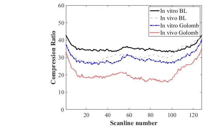
The comparison of compression ratios of the proposed BL and the conventional exponential Golomb codes is shown in Fig. 5. Here, we only compare the compression results for the baseband I/Q data sets as they provide similar compression ratios for both the in vitro and in vivo data sets. As shown in Fig. 5, the proposed BL code yields higher compression ratios than the exponential Golomb code. The average compression ratios with the proposed BL and exponential Golomb codes were 35.2% (in vitro BL) and 29.1% (in vitro Golomb), respectively, for in vitro data sets, while the ratios decreased to 31.7% (in vivo BL) and 20.7% (in vivo Golomb), respectively, for in vivo data sets.
Recently, ultrasound analog-front-end chips including programmable low noise amplifiers, gain amplifiers, LPFs, 12/14-bit ADCs, and quadrature demodulators with a decimator were introduced by some vendors such as TI and Analog Devices. In these chips, the demodulation is performed after ADC followed by the decimation with a factor of up to 16. For example, in 64-channel mid/low-end ultrasound imaging systems with a 12-bit ADC and sampling rate of 20 MHz, the data transfer rate can be reduced to 3.8 Gbits per second (Gbps) for the pre-beamformed I and Q data after digital
demodulation and four-fold decimation by incorporating such chips. Note that the total data rate to transfer both I and Q data is 7.6 Gbps. This data rate does not meet the USB 3.0 specification. However, with the proposed method, the data rate can be further reduced by 30%; then, the data rate would be 2.6 Gbps for the I/Q data, lowering the total data rate to 5.2 Gbps, which could be handled by USB 3.0 devices marginally.
4. Conclusion
In this paper, we proposed a lossless compression method, called BL code, for real-time software-based ultrasound imaging. The proposed method improved the compression ratio of the exponential Golomb code by reducing the prefix length. Because the bit length of the proposed prefix slowly increases as the code-num increases, an improved compression ratio was obtained. As the proposed method can encode integers using simple calculations, it can be implemented in real-time. The performance of the proposed method was validated using sample sets of ultrasound data. Our method could be applied in a wide range of data processing applications, especially in ultrasound image systems. In the future, we will implement the proposed method in an FPGA chip with a USB 3.0 interface on ultrasound imaging systems and assess its performance.
Author Contributions: Conceptualization, Supervision and Funding Acquisition, C.Y. and T.-K.S.; Methodology, J.H.K., S.Y., J.W.K. and K.K; Validation, J.H.K., S.Y., J.S.; Writing-Original Draft Preparation, J.H.K.; Writing-Review & Editing, J.H.K., C.Y and T.-K.S.
Acknowledgments: This work was supported in part by the National Research Foundation of Korea (NRF) grant funded by the Korea government (MSIP; Ministry of Science, ICT & Future Planning) (No. 2017R1C1B5016846) and R&D program of MOTIE/KEIT(10053241, Universal Ultrasonic diagnostic system development to support a dedicated Urology and Coloproctology and 10076675, Development of MR Based High Intensity Focused Ultrasound Systems for Brain and Urinogenital Diseases).
Conflicts of Interest: The authors declare no conflict of interest.
References
1. Karaman M., Atalar A.; Koymen H. VLSI circuits for adaptive digital beamforming in ultrasound imaging.
IEEE Trans. Med. Imaging 1993, 12, 711-720.
2. Kim G.; Yoon C.; S. Kye, Lee Y.; Kang J.; Yoo Y.; Song T.-K. A Single FPGA-based Portable Ultrasound Imaging System for Point-of-Care Application. IEEE Trans. Ultrason. Ferroelect. Freq. Contr.2012, 59, 1386-1394.
3. Kang J.; Yoon C.; Lee J.; Kye S.; Lee Y.; Chang J. H.; Kim G.; Yoo Y.; Song T.-K. A system-on-chip solution for point-of-care ultrasound imaging systems: Architecture and ASIC implementation. IEEE Trans. Biomed. Circuits Syst. 2016, 10, 412-423.
4. Kim Y.; Kim J. H.; Basoglu C.; Winter T. C. Programmable ultrasound imaging using multimedia technologies: A next-generation ultrasound machine. IEEE Trans. Inform. Technol. Biomed.1997, 1, 19-29. 5. Wang L. Acoustic Radiation Force Based Ultrasound Elasticity Imaging for Biomedical Applications.
Sensors2018, 18, 2252
6. Chang L. W.; Hsu K. H.; Li P. C. Graphics processing unit based high-frame-rate color Doppler ultrasound Processing. IEEE Trans. Ultrason. Ferroelectr. Freq. Contr.2009, 56, 1856–1860.
7. Techavipoo U.; Worasawate D.; Boonleelakul W.; Keinprasit R.; Sunpetchniyom T.; Sugino N.; Thajchayapong P. Toward Optimal Computation of Ultrasound Image Reconstruction Using CPU and GPU. Sensors2016, 16, 1986.
8. http://verasonics.com/vantage-systems/
9. Kim K. C.; Kim M. J.; Joo H. S.; Lee W. Yoon C.; Song T. –K.; Yoo Y. Smartphone-based portable ultrasound imaging system: A primary result. in Proc. IEEE Ultrason. Symp.2013, 2061–2063.
10. Li X.; Hu G.; Gao S. A novel B-mode ultrasound image compression method based on beam forming data. in Proc. 20th Annu. Int. Conf. IEEE Engineering in Medicine and Biology Society, 1998, 3, 1274–1276
11. Cheng P.; Shen C.; Li P. MPEG Compression of Ultrasound RF Channel Data for a Real-Time Software-Based Imaging System. IEEE Trans. Ultrason. Ferroelect. Freq. Contr.2012, 59, 1413-1420.
13. Ho Y. -S.; Jin H. Information theory and lossless encoding method. Seoul: Do-Yang Sa, 2009, 277–157 14. Huffman D. A. A method for the construction of minimum redundancy codes. Proc. I.R.E., 1952, 40, 1098–
1101.
15. Kim J.H. New Universal Code to Improve Unary Code Efficiency as Prefix Code of Exp. Golomb Code. The 3rd International Conference on Information, Electronics, and Communication Technology2017, 87-91.
16. Kim J. H. Binary data compression and decompression apparatus and method thereof. 2014, Korea Patent 10-1467684-0000.
17. Wagner R.; Insana M.; Brown D. Statistical properties of radio-frequency and envelop-detected signals with applications to medical ultrasound. J. Opt. Soc. Am. A.1987, 4, 910–922