DOI: 10.1051/epjconf/20122601050 c
Owned by the authors, published by EDP Sciences, 2012
Experimental study of aluminium honeycomb behaviour under dynamic
multiaxial loading
R. Tounsi
1,2, B. Zouari
1, F. Chaari
2, G. Haugou
2, E. Markiewicz
2, and F. Dammak
11National Engineering School of Sfax, U2MP, BP. W3038, Sfax, Tunisia
2University of Valenciennes and Hainaut-Cambresis. LAMIH, UMR 8201-CNRS, 59313 Valenciennes, France
Abstract. Split Hopkinson Pressure Bar system (SHPB) with large-diameter and Nylon bars introducing a shear-compression loading device is used in order to investigate the dynamic behaviour of aluminium honeycomb under multiaxial loadings
conditions. All shear-compression configurations including the loading angle variation from 0◦ to 60◦are performed with an
impact velocity of about 15 m/s. The adapted SHPB system with the device are validated numerically and a phenomenon of
separation between the input bar and the input beveled bar is observed. Numerical results suggest that this phenomenon provides a cutting of the reflected wave. An electro optical extensometer is employed in experiments. A good agreement between the
numerical elastic waves and the experimental ones is obtained. Experimental results show a significant effect of the loading angle
on the apparent stress-strain curves. The initial peak value and the plateau stress decrease with the increase of the loading angle. The combined shear-compression device with an enhancement at the alignment set-up provides efficient results for samples dynamically loaded. This device will be used to investigate the influence of the in-plane orientation angle on the deformation mechanisms and multiaxial behaviour of aluminium honeycomb under dynamic and quasi-static loading conditions.
1 Introduction
Cellular materials such as honeycombs combine high en-ergy absorption capacity and low density. The use of these materials in the field of transports contributes to improve the sustainability by reducing vehicle mass while main-taining the same safety level, and contributes to ensure passengers safety during crash events. Several studies have been performed by many authors such as Gibson and Ashby [1, 2]; Yang and Huang [3], Wu and Jiang [4]; Zhao and Gary [5]; Zhao et al. [6]; Doyoyo and Mohr [7] to understand the mechanical quasi-static and dynamic behaviour of these kind of material such as aluminium honeycombs that used for energy absorption application.
The experimental investigations reported in the liter-atures are limited to uniaxial compressive loading. How-ever, in the real crush event shear and compression are combined. Therefore, understand the multiaxial behaviour of such kinds of materials is necessary. A few numbers of investigations developed by Mohr and Doyoyo [8, 9] and Hong et al. [10] are focus on the aluminium honeycomb behaviour under quasi-static combined shear-compression loading. Under dynamic multiaxial loading conditions, some works are reported by Hong et al. [11] and recently Hou et al. [12, 13]. They have been investigated numeri-cally and experimentally the honeycomb behaviour under both case quasi-static and dynamic multiaxial loading conditions.
A test device developed by Hong et al. [11] has been realized in order to investigate the honeycomb dynamic multiaxial behaviour but this method suffers from poor measurement accuracy at higher loading rates. For this raison, a new combined shear-compression method using a large–diameter Nylon Split Hopkinson Pressure Bars (SHPB) set-up is adapted by Hou et al. [12, 13].
In this paper, this new testing method is used to per-form the dynamic multiaxial tests using a large diameter
(Ø=60 mm) Nylon bars. It is based on two short beveled bars inclined with different angle in order to achieve five loading angle from 0◦ to 60◦ by 15◦. The same material and diameter as the Hopkinson bars is used. FEM study is performed at the whole loading system in order to make sure of measurements accuracy given by the introducing beveled bars on the SHPB system. Virtual tests are per-formed at the loading angleΨ=0◦(axial case) in order to valid this processing data method with and without beveled bars.
All the tests are carried out at impact velocity around 15 m/s. Following this numerical study, some ameliora-tions are preformed in the test set-up in order to have an efficient accuracy on the results and investigate the effect of the in-plane orientationβ(angle between the shear load direction and the double wall thickness direction) that is not reported by Hou et al. [12, 13].
2 Enhancement of the combined
shear-compression device by FEM
Based on the combined shear-compression device devel-oped by Hou et al. [12, 13] introduced in the basis SHBP system, a numerical tests are performed. Ours objectives are to make sure of the accuracy of the measurements data and the deformation mechanisms. We observe that in all loading cases especially in the most severe case (the loading angle 60◦) the two short beveled are no longer aligned during the crash test. One way is to rigidify the sleeve that guides the two short bars without any effect on the data measurements and final results.
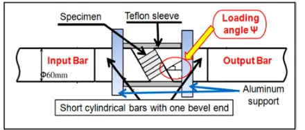
Fig. 1.Scheme of the combined shear-compression device [12].
no deviation of the short beveled. Two aluminium supports are used to fix the device in the SHBP system.
The specimen is placed between the two short beveled bars. To respect the wave propagation low from the in-put/output bars to the input/output beveled bars without any significant reflections or effects. The two beveled bars have the same material and diameter of the Hopkinson bars.
The same measuring method with classical Hopkinson system with large diameter and viscoelastic bars is used. This method based on the one-dimensional elastic wave theory has been validated by Zhao and Gary [14]. But the introduction of the combined shear-compression device on the SHPB system can be caused the friction between the Teflon sleeve and the beveled bars and an error on the displacement measurement of specimens. In fact, some assumptions are needed to valid the using of this device to achieve the multiaxial behaviour of cellular materials under dynamic loading conditions. In order to verify those two assumptions suggested by Hou et al. [12, 13], a nu-merical study of the complete loading system (device and SHBP) is carried out.
When we simulate the loading system in the case dy-namic combined shear-compression loading, we observe that the Teflon sleeve swells causing a bad alignment of the short beveled bars during the experiments.
2.1 FE model
The finite element model is composed by a projectile, two input and output Hopkinson bars and a combined shear-compression loading device. The components of this device are two short beveled bars, a Teflon sleeve, a Steel sleeve, two supports and the specimen. To validate the efficiency of the whole system, the most severe case with loading angle Ψ = 60◦ is established. The same dimensions of all part of the loading system are used.
8-node linear brick elements with reduced integration (C3D8R) are used. The element size is 5 mm for the bars, the sleeves and supports, while 3 mm for the bevels and 1.5 mm for the specimen (figure 2). For the specimen, the constitutive behaviour is described by a crushable foam model, here you give the most important behaviour is the plastic that dominates the elastic behaviour (table1).
For the projectile, bars and beveled bars, linear material with elastic constants of Nylon is used. For the Teflon sleeve, Steel sleeve and supports, linear material with elas-tic constants of Teflon, Steel and Aluminium respectively is used. The material proprieties are listed in table 2.
Fig. 2. Finite element model of SHPB with combined shear-compression loading device.
Table 1.Honeycomb material properties.
Honeycomb
Densityρ(kg/m3) 82.6
Young’s Modulus E (MPa) 450
Poission’s Ratioν 0.35
Plastic Possion’s Ratioνp 0
Yield Stressσs (MPa) 3.22
Lock Strainεlock 0.72
Table 2. The material proprieties of Nylon, Teflon, Steel and Aluminium.
Densityρ Young’s Modulus Poission’s
(kg/m3) E (MPa) Ratioν
Nylon 1120 3370 0.3
Teflon 2200 1500 0.46
Steel 7800 210000 0.295
Aluminium 2700 70000 0.35
Surface to surface contact is defined between the in-terface of projectile/Hopkinson input bar and Hopkinson bars/beveled bars with frictionless contact property. At the interfaces between the specimen and the beveled bars, surface-to-surface contact with penalty contact method is applied. A Coulomb friction coefficient is equal to 0.5. The penalty contact method is applied between the Steel sleeve, the Teflon sleeve and the Nylon bars with a friction coefficient are set to be 0.05.
The real impact velocity measured in the experiment is 15 m/s that used to initialise the velocity of the projectile in axial (Z) direction. The bottom surface of the two supports is restricted on three translational displacements and rotations that correspond to the realistic boundary loading conditions. Two elements located on the external surface of the input and output bars corresponding to the positions of strain gauges are picked. The position of the strain gauges is shown in figure 3 with the SHPB set-up.
The software ABAQUS/Explicit is used to simulate the numerical crash tests with the adopted SHPB set-up.
2.2 FE model results
Fig. 3.The SHPB set-up and the strain gauge positions.
0 50 100 150 200 250 300
0,0 0,2 0,4 0,6 0,8 1,0
DEFORMATION (mm)
True distance (mm)
Teflon 5 mm + Acier 10 mm Teflon 20 mm
Fig. 4.The sleeve rigidifying: the swelling of the Teflon (20 mm)
and the Teflon+Acier (5 mm+10 mm) sleeves during the crash.
0,0 0,1 0,2 0,3 0,4 0,5 0,6 0,7 0,8 0,9 1,0 1,1 1,2 1,3 1,4 1,5 -0,006
-0,005 -0,004 -0,003 -0,002 -0,001 0,000 0,001 0,002 0,003 0,004 0,005
Strain
Time (ms) incident wave_without Beveled reflected wave_without Beveled transmitted wave_without Beveled incident wave_with Beveled reflected wave_with Beveled transmitted wave_with Beveled
Beveled bar effect
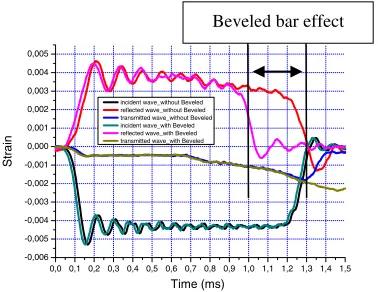
Fig. 5.The three elastic waves with and without beveled bars
under axial loading (Ψ=0◦).
the use of a Teflon sleeve with an aluminium sleeve needed an important thickness for obtaining a good alignment of the beveled during the test. Some numerical tests provide that a thickness of 5 mm of Teflon sleeve and 10 mm of Steel sleeve gives a deformation at the top of 0.06 mm smaller than 1 mm with only one Teflon sleeve (20 mm). At the window the two sleeves ensures a deformation of 0.13 mm and this is so smaller comparing to 2 mm with only one Teflon sleeve. These two sleeves thicknesses provide a good alignment during the crash test and ensure the no deviation of the two short bevelled bars during test (figure 4).
A separation at the interface of the Hopkinson input bar and the input beveled bar was observed. This phenomenon provides a cut in the reflected wave. The strain input and output pulses are recorded in the case of axial loading with and without beveled. They are separated to show each wave only (figure 5). A delay in return of the wave is observed. The reflected wave has a short duration as the incident wave and that it causes a restriction of the data
Fig. 6.Combined shear-compression loading device.
measuring of the global force and velocity. Therefore, in ours experiments an electro optical extensometer (Rudolph XR 200) is needed to calculate the shortening of the sample. The main objective is to obtain more information in the stress-strain curve.
3 Combined shear-compression loading
SHPB technique is an efficient tool to characterize the material impact behaviour since decades. This technique was used at a first step for metallic materials after works of authors. Zhao and Gary [14] have adapted kolsky technique to characterise many different materials by using a large diameter and viscoelastic bars. The use of the large diameter is performed in order to have a large cross section and a better impedance, to improve the sample/cell size ratio and to reduce the data scatter. Zhao and Gary [14] require some precautions in the wave-shift procedure to valid the elastic waves’ system propagating in the viscoelastic bars and to consider the dispersion phenomena due to the large diameter. These requirements are employed to investigate the impact loading test for much kind of cellular materials. In this paper, a typical SHPB set-up composed by two bars (2 × 3 m) and a projectile (1 m) with a same diameter 60 mm is proposed. The first gauge is placed at midpoint of the input bar and the second is placed at 0.4 m of the output bar (figure 3). The main role of these gauges is to record the three elastic waves after ampli-conditioning process.
3.1 Combined shear-compression device
The combined shear-compression device is introduced in the typical SHPB set-up in order to investigate the mul-tiaxial behaviour of cellular material such as honeycomb, hollow sphere, assemblies. This device is composed by two short inclined bars with different loading angle (from 0 to 60◦ with an incremental angle equal to 15◦), coaxial Teflon and steel sleeves and two aluminium supports. Figure 6 shows in details the experimental combined shear-compression loading device. The specimen is placed between the two short beveled bars such as show in figure 6 and 7.
Fig. 7.The combined shear-compression loading device in the axial loading case.
Fig. 8.The combined shear-compression loading device in the
multiaxial loading case (Ψ=30◦).
specimen/output bar) and others experiments using the device with short inserted bars such as given in figure 6 and 7. The introducing of this device has the same effect mentioned by the numerical study at the measuring of the three elastic waves. The separation phenomenon of the input bar and the input short beveled bar is observed dur-ing experimental tests. Aluminium hexagonal honeycomb Al5056-O is used to achieve some experiments under axial and multiaxial loadings (figure 7 and 8). Two cell sizes are employed (d1 =6.35 mm and d2 =4.7625 mm), the cell wall thickness is 76µm and 50.8µm respectively. The specimen dimensions are 41×45×25 mm for Al5056-6-1/4-0.003 and 42×42×25 mm for Al5056-5.7-3/16-0.002. A projectile launched by a gas gun strikes the free end of the input bar. A compressive longitudinal incident wave
εi(t) is generated in the input bar. Once this wave reaches
the bar/specimen interface, a part of it manned εr(t), is
reflected, whereas the other part goes through the specimen and develops as the transmitted waveεt(t) in the output bar. Figure 9 shows these three waves under dynamic axial loading.
Some assumptions should be respected such as the one-dimensional wave propagation theory, the homogenous stress and strain fields in the specimen and the inertia effect and the neglected friction between the specimen and the ends of bars. Based on the three elastic waves, the current strain rate, strain and stress of the specimen can be calculated as apparent values:
˙
εs(t)=
2CD
L εr(t) (1)
0,0 0,1 0,2 0,3 0,4 0,5 0,6 0,7 0,8 0,9 1,0 1,1 1,2 1,3 1,4 1,5 -0,005
-0,004 -0,003 -0,002 -0,001 0,000 0,001 0,002 0,003 0,004
STRAIN
Time (ms) incident wave reflected wave transmitted wave
Fig. 9. The three elastic waves under axial loading (Ψ = 0◦) experimental results.
0,0 0,1 0,2 0,3 0,4 0,5 0,6 0,7 0,8 0,9 0
2 4 6 8 10 12 14 16 18 20
Force (kN)
Time (ms)
INPUT OUTPUT
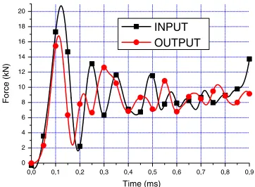
Fig. 10.Input and output forces’ equilibrium under axial loading
(Ψ=0◦).
εs(t)=
2CD
L t
D
εr(t)dt (2)
σs(t)=E
A As
εt(t) (3)
where As is the area of specimen cross section, L is the
specimen length,AandEare respectively the cross section area and Young’s Modulus of Hopkinson bars,C0 is the elastic wave speed in bars. In addition, based on the three elastic waves, the input and output forces and velocities can be calculated directly by the following equations:
Finput(t)=AE(εi(t)+εr(t)) (4)
Foutput(t)=AEεt(t) (5)
Vinput(t)=C0(εi(t)−εr(t)) (6)
Voutput(t)=C0εt(t) (7)
0,0 0,2 0,4 0,6 0,8 1,0 1,2 1,4 -2
0 2 4 6 8 10 12 14
Velocity (m/s)
Time (ms)
INPUT OUTPUT
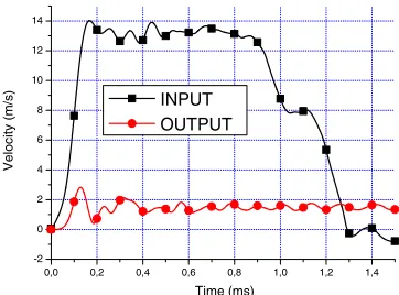
Fig. 11.Input and output velocities under axial loading.
0 2 4 6 8 10 12 14 16
0 10 20 30 40
Force (kN)
DISP (mm)
INPUT INPUT_EXT OUTPUT OUTPUT_EXT
DAVID Extensometer
Fig. 12. Comparison between the input and the output forces
using Davidc and the extensometer technique (Ψ=0◦).
0,0 0,1 0,2 0,3 0,4 0,5 0,6 0,7 0,8 0
1 2 3 4 5 6 7 8
Stress (MPa)
Strain
ECH_1_3/16 ECH_2_3/16 ECH_3_3/16
Fig. 13.Comparison between three impact experiments on
hon-eycomb under axial compression loading (Ψ=0◦).
3.2 Effects of beveled bars on data process method
In order to investigate the influence of the beveled bars on the data calculations, a comparative study is achieved in terms of the three elastic waves recorded directly by the strain gauges cemented on the cylindrical bars.
Due to the separation of the input bar and the input beveled bar during the crash testing and to the limit calculations by Davidc [15]. Output forces and shortening of the sample are plotted in function of values provided by output bar and electro-optical extensometer, respectively (figure 12). Three experimental tests per velocity are per-formed for each loading case (with variation of the loading angle and the orientation angle).
Figure 13 shows the stress/crush curves for Ψ = 0◦. The three curves show the same shape with a very
0,0 0,1 0,2 0,3 0,4 0,5 0,6 0,7 0,8 0
2 4 6 8 10
Stress (MPa)
Strain
ECH_1_1/4 ECH_1_3/16
Fig. 14.Comparison between honeycomb with different size cell
under axial compression loading (Ψ=0◦).
0,0 0,1 0,2 0,3 0,4 0,5 0,6 0,7 0
2 4 6 8 10
Stress (MPa)
Strain
ECH_1_0°/0°_1/4 ECH_1_15°/0°_1/4 ECH_1_30°/0°_1/4 ECH_1_45°/0°_1/4
Fig. 15.Comparison between honeycomb with different size cell
under axial compression loading (Ψ=0◦).
small difference. Therefore, a good repeatability was con-firmed for the dynamic loadings using the combined shear-compression device.
Figure 14 shows the influence of the cell size on the stress strain curves. It is found that the stress peak value and the plateau stress of the big size specimen are higher than the one of the small cell size specimen. The deformation mechanisms of these two specimens is almost the same and no effect of the cell size on the mechanisms of deformation that begin by the formation of the first fold and after that a progressive folding system is observed.
The obtained dynamic stress/strain curves show that both the initial peak value and the average plateau stress decrease significantly with the increase of the loading angle (figure 15).
4 Conclusions and perspectives
Acknowledgements
This research is conducted through collaboration between the University of Valenciennes and the National Engineering School of Sfax. This collaboration is jointly financed by the National Centre of Scientific Research and the General Direction of Scientific Research in Tunisia (DGRS-CNRS 11R11-33). The present research work has also been supported by the Inter-national Campus on Safety and Intermodality in Transportation, the Nord-Pas-de-Calais region, the European Community, the Regional Delegation for Research and Technology, and by the Ministry of Higher Education and Research. The authors grate-fully acknowledge the support of these institutions.
References
1. L.J. Gibson and M.F. Ashby, Cellular Material: Struc-ture and Properties, second ed. Cambridge University Press, Cambridge, UK. (1997).
2. L. J. Gibson, M. F. Ashby. Cellular Solids. Pergamon Press, Oxford, (1988).
3. M. Y. Yang, J. S. Huang. Elastic buckling of regular hexagonal honeycombs with plateau borders under biaxial compression. Compo. Struct. 71, 229–237 (2005).
4. E. Wu, W. S. Jiang, Axial crush of metallic honeycombs, Int. J. Impact Engng. 19, 439–456 (1997).
5. H. Zhao, G. Gary, Crushing behavior of aluminium honeycombs under impact loading. Int. J. Impact En-gng.21, 827-836 (1998).
6. H. Zhao, I. Elnasri, S. Abdennadher. An experimental study on the behavior under impact loading of metal-lic cellular materials. Int. J. Mech.Sci. 47, 757–774 (2005).
7. D. Mohr, M. Doyoyo, Nucleation and propagation of plastic collapse bands in aluminium honeycomb. J. Appl. Phy.94, 2262–2270 (2003).
8. D. Mohr, and M. Doyoyo, Deformation-induced folding systems in thin-walled monolithic hexagonal metallic honeycomb, Int. Journal of Solids and Structures 41, 3353–3377, (2004).
9. D. Mohr, and M. Doyoyo, Experimental investigation on the plasticity of hexagonal aluminium honeycomb under multiaxial loading. J. Appl. Mech.71, 375–385, (2004).
10. S.T. Hong, J. Pan, T. Tyan and P. Prasad, Quasi-static crush behavior of aluminum honeycomb specimens under compression dominant combined loads, International Journal of Plasticity22, 73–109, (2006).
11. S.T. Hong, J. Pan, T. Tyan and P. Prasad, Dynamic crush behaviors of aluminum honeycomb specimens under compression dominant inclined loads. Int. J Plasticity24, 89–117, (2008).
12. B. Hou, A. Ono, S. Abdennadher, S. Pattofatto, Y.L. Li and H. Zhao, Impact behavior of honeycombs un-der combined shear-compression. Part I: Experiments, International Journal of Solids and Structures, 48, 687–697, (2011).
13. B. Hou, S. Pattofatto, Y.L. Li and H. Zhao, Impact behavior of honeycombs under combined shear-compression. Part II: Analysis, International Journal of Solids and Structures. 48, 698–705, (2011).
14. Zhao, H., Gary, G., Klepaczko, J.R., On the use of viscoelastic split Hopkinson pressure bar. Int. J. Impact Eng.19, 319–330, ( 1997).