Future M obile Satellite System s: Issues in Tim ing
Synchronisation and R esource A llocation
Techniques
A th esis su b m itted for th e degree o f D o cto r o f P h ilo so p h y
in E lectron ic and E lectrical E ngineering
A ikaterini K ou tsaftik i
UCL
ProQuest Number: 10014989
All rights reserved
INFORMATION TO ALL USERS
The quality of this reproduction is dependent upon the quality of the copy submitted.
In the unlikely event that the author did not send a complete manuscript and there are missing pages, these will be noted. Also, if material had to be removed,
a note will indicate the deletion.
uest.
ProQuest 10014989
Published by ProQuest LLC(2016). Copyright of the Dissertation is held by the Author.
All rights reserved.
This work is protected against unauthorized copying under Title 17, United States Code. Microform Edition © ProQuest LLC.
ProQuest LLC
789 East Eisenhower Parkway P.O. Box 1346
A cknow ledgem ents
I would like to thank Dr. Phil M. Lane for his guidance and assistance in preparing this project. I would also like to extend my sincerest thanks to Professor John O ’Reilly for his continuing encouragement and advice.
I am also deeply grateful to Dr. Chris Matrakidis for his wealth of knowledge and his invaluable technical and moral support.
I would also like to thank Nokia Mobile Phones (UK) Ltd for the financial sup port. Especially, I would like to thank Dr. Assimakis Kokkos and Ian Macnamara who contributed to my work with many fruitful discussions. I would also like to thank Dr. Richard Fehlmann and Petri Gronberg for their informative comments and technical assistance.
K)nny
A bstract
In an era where the personal communication character of the user is the main technology focus, the convergence of mobile satellite and mobile terrestrial systems seems not too distant. The extend of the integration of the satellite-based and the terrestrial-based systems introduces m ajor architectural challenges.
The first chapter of this thesis presents a general overview of the mobile satellite systems, presents the organisation of the thesis and details the main contributions.
In the second chapter some background information relevant to the research is presented. Specifically, aspects of GSM and GPRS are presented. Additionally, after a brief description of S-PGSs, the subject of satellite and GSM integration is addressed.
In the third chapter issues regarding tim ing synchronisation, when GSM is inte grated with a satellite system, are examined, and solutions to mitigate parts of the problems identified are proposed.
In the fourth chapter the GPRS system is examined in the satellite environ ment. The research is focused in the G PR S’s RLC/MAG protocol, which is mainly responsible for the allocation of resources amongst the users.
Dynamic Ghannel Allocation (DGA) techniques, are expected to improve dra matically the efficiency of the resources allocation issue, by allowing a more intelli gent use of the limited spectrum available for mobile communications. In the fifth chapter, novel DGA algorithms are introduced and are examined for purposes of resources allocation for mobile satellite systems.
In the sixth chapter heuristic algorithms are used in combination with the pro posed DGA schemes in order to offer a further optimisation in the systems examined. Simulated annealing, is incorporated to the real-time system scenarios, in contrast to its conventional use for non-dynamic systems and major benefits to the systems are introduced.
C ontents
1 In trod u ction 14
1.1 Background and M o tiv a tio n ... 14
1.2 Organisation of the T h e s i s ... 15
1.3 Summary of main c o n trib u tio n s ... 16
2 G eneral B ackground 19 2.1 In tro d u c tio n ... 19
2.2 G S M ... 19
2.2.1 GSM s e r v ic e s ... 21
2.2.2 The GSM Network [3, 4, 5] 22 2.2.3 GSM Radio Interface [2, 6 ] ... 25
2.2.4 GSM protocol structure ... 30
2.3 G P R S ... 31
2.3.1 GPRS n e t w o r k ... 33
2.3.2 GPRS protocol s t a c k ... 34
2.3.3 The GPRS air interface ... 40
2.4 S -P G S s... 43
2.4.1 General satellite system d e s c rip tio n ...44
2.4.2 Major S -P C S s... 46
2.4.3 GSM and S-PCSs i n t e g r a t i o n ... 50
2.4.4 ‘Satellite fixed cell’ and ‘earth-fixed cell’ satellite systems . . 53
2.5 S u m m a r y ... 56
3 T im in g S yn ch ro n isa tio n for G SM over a sa te llite sy ste m 58 3.1 In tro d u c tio n ... 58
3.2 Synchronisation and timing advance f e a t u r e ... 59
3.3 Satellite-fixed cell p a t t e r n ... 61
3.3.1 System a n a ly s is ... 61
3.3.2 Results and d is c u s s io n ...64
3.4 Earth-fixed cell p a t t e r n ... 74
3.4.1 System a n a ly s is ... 75
3.4.2 Results and d is c u s s io n ... 80
Packet S w itch in g Services over S a tellite R ad io S ystem s 86
4.1 In tro d u c tio n ... 86
4.2 Simulation tool and framework ... 87
4.2.1 Optimised Network Engineering Tools ... 87
4.2.2 Simulation framework ... 89
4.3 Analytical m o d e ls ...94
4.3.1 First m o d e l ...96
4.3.2 Second m o d e l... 101
4.3.3 Third m o d e l...102
4.3.4 Fourth m o d e l ... 104
4.4 R e s u lts ... 109
4.4.1 General p e rfo rm a n c e ...109
4.4.2 Impact of the ARQ scheme ...113
4.4.3 Multislot operation ...118
4.4.4 Improved p e rfo rm a n c e ... 122
4.5 C o n c lu sio n s ... 126
H eu ristic tech n iq u es for tim e invariant sa te llite D C A p roblem s 130 5.1 In tro d u c tio n ... 130
5.2 Combinatorial p r o b le m s ...131
5.3 Heuristic T e c h n iq u e s ... 131
5.3.1 Hill C lim b in g ... 133
5.3.2 Steepest D e s c e n t ...133
5.3.3 Simulated A n n e a lin g ... 134
5.4 Fixed and dynamic channel allocation techniques ... 135
5.5 Resource Allocation Heuristics ...136
5.5.1 Results and D iscu ssio n ... 143
5.6 C o n c lu s io n s ... 148
Im proved d yn am ic channel a llocation for sa te llite system s: novel algorith m s and con stan t tem p eratu re annealing 152 6.1 In tro d u c tio n ... 152
6.2 General model background and d e sc rip tio n ... 153
6.2.1 Model B a c k g ro u n d ...153
6.2.2 Model Description ...155
6.3 DCA te c h n iq u e ...157
6.4 Simulation framework ...160
6.5 Results and d is c u s s io n ... 162
6.6 Simulated Annealing for Dynamic P r o b le m s ...167
6.6.1 Concept description ... 167
6.6.2 Application and discussion ... 168
List o f Figures
2.1 GSM Bearer services and teleservices ... 21
2.2 GSM Network Architecture ... 23
2.3 Multiframes, TDM A frames and bursts in G S M ... 26
2.4 Flow diagram of encoding and modulating a full-rate T G H ...29
2.5 GSM signalling Protocol A rch itectu re... 32
2.6 The GPRS network ... 34
2.7 The GPRS transmission p l a n e ... 36
2.8 Example of USE sharing between two mobiles ...38
2.9 Packet transformation data f lo w ...39
2.10 The GPRS air interface ...41
2.11 Two cases of packet transfer: MS initiated and network in itia te d ...42
2.12 General components of a satellite system ...45
2.13 An illustration of the Iridium constellation with the solar cell arrays point ing in every w a y ...48
2.14 The coverage areas of Iridium satellites constellation ... 48
2.15 ICO system overview [13] 49 2.16 The footprint pattern for earth-flxed cell satellite sy stem s...54
2.17 Handover between earth-flxed satellite c e l l s ... 55
3.1 Geometrical considerations... 62
3.2 The number of rings used for a;dp=35 km ...66
3.3 The number of satellites used for Xdp=35 km and various sets of n . . . . 67
3.4 Distance between consecutive rings...68
3.5 Different cell pattern layouts for different number of rings and directivity requirements [2 7 ]...72
3.6 Example of a satellite footprint design using trapezium shaped cells . . . . 72
3.7 Earth-flxed footprint division... 75
3.8 Geometric considerations for the ‘earth-fixed’ p a t t e r n ... 76
3.9 Earth-flxed footprint division... 79
3.10 Number of areas for a LEO system (h=800 km) versus ...81
3.11 Number of satellites for a LEO system (h=800 km) versus ... 81
3.12 Number of areas for a MEO system (h= 10000 km) versus ... 82
3.13 Number of satellites for a MEO system (h= 10000 km) versus ^ p ...82
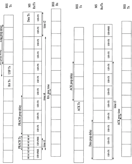
3.15 Distance between consecutive areas that are located in the footprint diameter for a MEO system (h= 10000 km, el = 30°, = 4°) versus the number of a r e a ... 84 4.1 The OPNET modelling structure [ 3 7 ] ... 88 4.2 The general m o d e l...91 4.3 Transmission and reception windows structure in the MS and the BBS . . 95 4.4 The timing structure of the first model of analysis...98 4.5 LLC end-to-end frame delay for the Railway model for: i.CS-l,BLER=0.0002
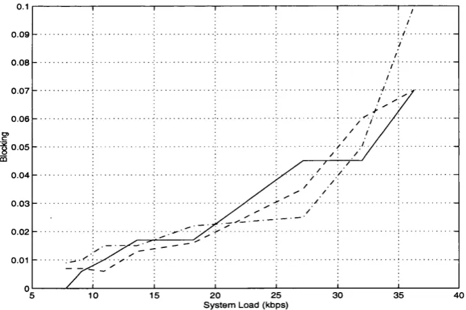
(solid line), n.CS-l,BLER=0.08 (-.), m.CS-3,BLER=0.02 ( - ) ...110 4.6 LLC frame blocking for the Railway model for: î.CS-1,BLER=0.0002 (solid
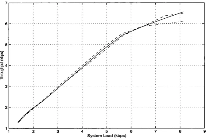
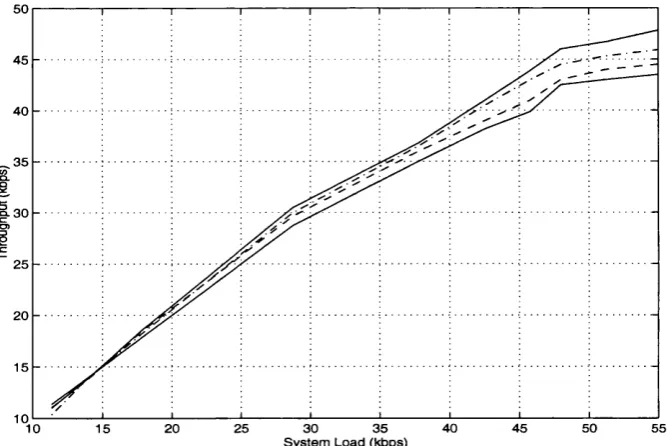
line), n.CS-l,BLER=0.08 (-.), m.CS-3,BLER=0.02 (-) ...110 4.7 LLC frame throughput for the Railway model for: z.CS-l,BLER=0.0002
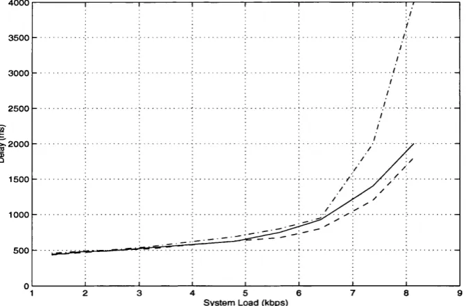
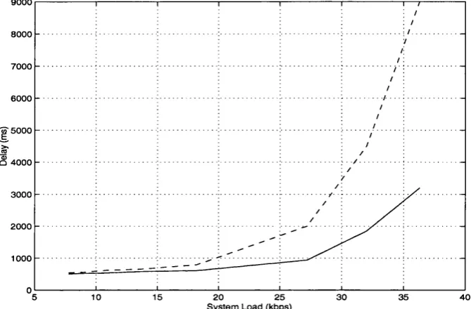
(solid line), m.CS-1,BLER=0.08 (-.), m.CS-3,BLER=0.02 ( - ) ...I l l 4.8 LLC frame delay for the Mobitex model for: iCS-l,BLER=0.0002 (solid
line), m.CS-1,BLER=0.08 (-.), m.CS-3,BLER=0.02 (-) ... I l l
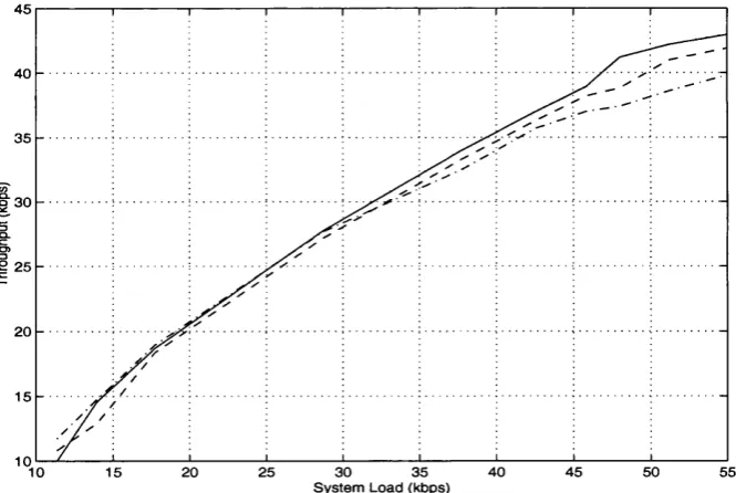
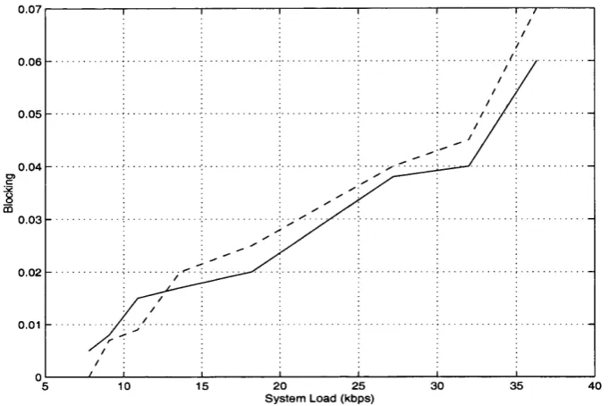
4.9 LLC frame blocking for the Mobitex model for: z.CS-l,BLER=0.0002 (solid line), m.CS-1,BLER=0.08 (-.), m.CS-3,BLER=0.02 ( - ) ... 112 4.10 LLC frame throughput for the Mobitex model for: iCS-l,BLER=0.0002
(solid line), n.CS-l,BLER=0.08 (.-), m.CS-3,BLER=0.02 ( - ) ...112 4.11 Delay for the FUNET model for BLER=0.0002: z. K=30, WIN=64 (solid
line), ii. K=64, WIN=64 (- line), m. K=60, WIN=80 (-. line), iv. K=64, WIN=110 (solid-dotted lin e ) ...114 4.12 Throughput for the FUNET model for BLER=0.0002: i. K=30, WIN=64
(solid line), ii. K=64, WIN=64 (- line). Hi. K=60, WIN=80 (-. line), iv. K=64, WIN=110 (solid-dotted l i n e ) ... 114 4.13 Delay for the FUNET model for BLER=0.02: i. K=30, WIN=64 (solid
line), ii. K=64, WIN=64 (- line). Hi. K=110, WIN=133 (-. line) . . . . 115 4.14 Throughput for the FUNET model for BLER=0.02: i. K=30, WIN=64
(solid line), ii. K=64, WIN=64 (- line). Hi. K=110, WIN=133 (-. line) . . 115 4.15 LLC frame delay for the Railway model for 3-slot operation: i. BLER=0.08
(- line) , ii. BLER=0.0002 (solid line) ... 118 4.16 Blocking probability for the Railway model for 3-slot operation: i. BLER=0.08
(- line) , ii. BLER=0.0002 (solid line) ... 119 4.17 Throughput for the Railway model for 3-slot operation: i. BLER=0.08 (-
line) , ii. BLER=0.0002 (solid l i n e ) ... 119 4.18 LLC frame delay for the Mobitex model for 3-slot operation: i. BLER=0.08
(- line) , ii. BLER=0.0002 (solid line) ... 120 4.19 Blocking probability for the Mobitex model for 3-slot operation: i. BLER=0.08
(- line) , ii. BLER=0.0002 (solid line) ... 120 4.20 Throughput for the Mobitex model for 3-slot operation: i. BLER=0.08 (-
line) , ii. BLER=0.0002 (solid l i n e ) ...121 4.21 LLC frame delay for the FUNET model for 3-slot operation, BLER=0.0002
10
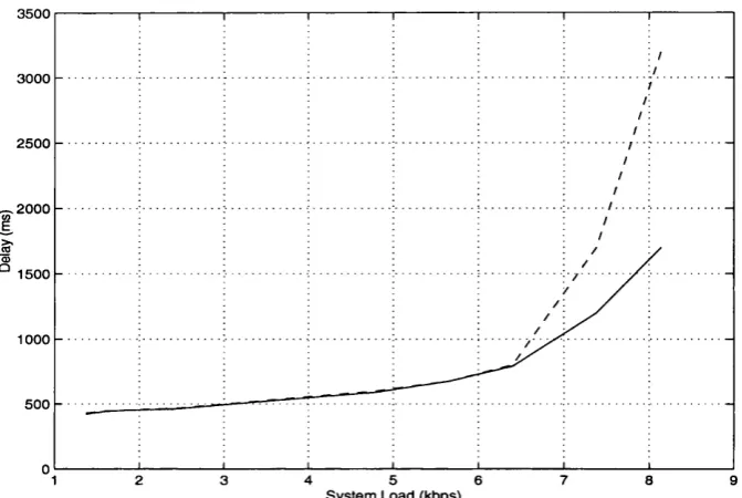
4.22 Throughput for the FUNET model for 3-slot operation, BLER=0.0002 (solid line), BLER-0.02 (-line), K=30, WIN=64 ... 123 4.23 LLC frame delay for the Mobitex model for: i. system load = 6.4 kbps,
second scheme (upper solid line) , ii. system load = 6.4 kbps, first scheme (upper dotted line) , iii. system load = 4.8 kbps, second scheme (bottom solid line), iv. system load = 4.8 kbps, first scheme (bottom dotted line) . 125 4.24 LLC frame blocking for the Mobitex model for: i. system load = 4.8
kbps, second scheme ( solid line) , ii. system load = 4.8 kbps, first scheme (dotted l i n e ) ... 126 4.25 LLC frame blocking for the Mobitex model for: i. system load = 6.4 kbps,
second scheme (solid line) , ii. system load = 6.4 kbps, first scheme (dotted line) ... 126 4.26 LLC frame delay for the Railway model for: i. system load = 32 kbps,
first scheme (upper solid line), ii. system load = 32 kbps, second scheme (upper dotted line) , iii. system load = 13.6 kbps, second scheme (bottom solid line), iv. system load = 13.6 kbps, first scheme (bottom dotted line) 127 4.27 LLC frame delay for the Railway model for: i. system load = 13.6 kbps,
second scheme ( solid line) , ii. system load = 13.6 kbps, first scheme (dotted l i n e ) ... 127 4.28 LLC frame delay for the Railway model for: i. system load = 32 kbps,
second scheme (solid line) , ii.system load = 13.6 kbps, first scheme (dotted line) ... 128 5.1 A seven cell frequency reuse p a t t e r n ... 137 5.2 The interference radius dmin versus the maximum number of customers
that can be served in the area A ... 139 5.3 Results for the dsumin the random initial configuration after the use of
the three heuristics presented in section 5.3 and the second cost function (n=l,2) presented in section 5.5 (simulated annealing and n=2 marked with solid line, hill climbing and n=2 marked with steepest descent and n=2 marked with hill climbing and n = l marked with ‘- ’) ... 144 5.4 Results for the dgamin for the random initial configuration after the use
of the first algorithm presented in section 5.5 (marked with ‘...’) and the combination of simulated annealing with both the second (n=2) (solid line) and third cost functions (marked with ‘- ’) presented in section 5.5 . . . . 145 5.5 Results for the dsa^in for the worst initial configuration after the use of
the three heuristics presented in section 5.3 and the second cost function (n=l,2) presented in section 5.5 (simulated annealing and n=2 marked with solid line, hill climbing and n=2 marked with steepest descent and n=2 marked with hill climbing and n = l marked with ‘- ’) ... 146 5.6 Results for the dga^in for the worst initial configuration after the use of
11
5.7 Results for the dsa average for the random initial configuration after the use of the three heuristics presented in section 5.3 and the second cost function (n=l,2) presented in section 5.5 (simulated annealing and n=2 marked with solid line, hill climbing and n=2 marked with steepest descent and n=2 marked with hill climbing and n = l marked with 148 5.8 Results for the dsa average for the random initial configuration after the
use of the first algorithm presented in section 5.5 (marked with ‘...’) and the combination of simulated annealing with both the second (n=2) (solid line) and third cost functions (marked with presented in section 5.5 . . 149 5.9 Results for the dsa average for the worst initial configuration after the
use of the three heuristics presented in section 5.3 and the second cost function (n=l,2) presented in section 5.5 (simulated annealing and n=2 marked with solid line, hill climbing and n=2 marked with steepest descent and n=2 marked with hill climbing and n = l marked with 150 5.10 Results for the dsa average for the worst initial configuration after the
use of the first algorithm presented in section 5.5 (marked with ‘...’) and the combination of simulated annealing with both the second (n=2) (solid line) and third cost functions (marked with ‘- ’) presented in section 5.5 . . 151 6.1 The cellular network used in the sim u la tio n ...162 6.2 Results of all three proposed algorithms (third, first and second algorithm
marked with ‘o’, and ‘x’ respectively)...163 6.3 Comparison of the two best performing algorithms (first and second algo
rithm marked with and respectively) with results using a cell-based DCA algorithm from [55] (marked with ‘x’) and FCA (solid l i n e ) ... 164 6.4 System general state diagram ...169 6.5 Results from the first algorithm with (marked with ‘o’) and without (marked
with ‘*’) the effects of a n n e a lin g ... 170 6.6 Results from the second algorithm with (marked with ‘-t-’) and without
(marked with ‘.’) the effects of annealing ... 171 6.7 Results from the third algorithm with (marked with ‘x’) and without
(marked with ‘*’) the effects of a n n e a lin g ... 171 6.8 Comparison of the results of all three algorithms (first second and third
algorithm marked with ‘o’, ‘-f’ and ‘x’ respectively) including the effects of annealing ... 172 6.9 The blocking probability for the second algorithm from section 6.3 without
annealing (‘x’) and with annealing for ^ = 5 (‘o’), ^ = 2 (‘4-’) and {K = 1,M = 1) (‘*’)...173 6.10 The blocking probability for the third algorithm from section 6.3 without
annealing (‘x’) and with annealing for ^ = 5 (‘o’), ^ = 2 (‘-I-’) and (K = l , M = l) (‘*’)...174 6.11 The blocking probability for the second algorithm from section 6.3 for
{K = 7 ,M = 1) (‘o’), (K = 3 ,M = 3) (‘-H’) and {K = 1,M = 1) (‘*’). . . 175 6.12 The blocking probability for the third algorithm from section 6.3 for {K =
12
6.13 The blocking probability for the second algorithm from section 6.3 for = = 15) (‘o’), {K = 10,M = 40) (‘-f-’) and { K = l , M = l ) (‘*’). . 176 6.14 The blocking probability for the third algorithm from section 6.3 for [K =
List o f Tables
2.1 GPRS coding s c h e m e s... 43
2.2 Different orbit parameters [1 1 ]... 46
2.3 Major S-PCSs system parameters [ 1 2 ] ... 47
3.1 The ratio a = |^ for different satellite altitudes and elevation angles . . . 64
3.2 Application to Iridium and ICO c h a n n e ls ... 73
3.3 Application to Iridium and ICO type of constellations... 83
4.1 Analytical and simulation W without noise in the s y s te m ...100
4.2 Analytical and simulation W with noise in the system ...102
4.3 Analytical and simulation W with noise in the system for a packet con sisting of 10 b lo c k s 104 4.4 Analytical and simulation W with noise in the system for a packet of size following the exponential d is trib u tio n ...108
4.5 Delay improvement when 3-slot scheme is used instead of single-slot scheme, for the Mobitex model for two different B L E R s ...121
4.6 Delay improvement when 3-slot scheme is used instead of single-slot scheme, for the Railway model for two different BLERs ... 122
4.7 Delay improvement when 3-slot scheme is used instead of single-slot scheme, for the FUNET model for two different B L E R s ... 122
5.1 The maximum number of customers that can be accommodated in a seven cell frequency re-use scenario versus the minimum interference distance dmin ...139
5.2 Results for dsa and dsamin foi" the first algorithm presented in section 5.5 . 143 5.3 Results for dsa and for a combination of simulated annealing and the second cost function (n=2) presented in section 5 . 5 ...144 5.4 Results for dsa and dsamin for a combination of simulated annealing and
the third cost function presented in section 5.5 145
C hapter 1
Introduction
1.1
Background and M otivation
Until recently satellite communications were mainly considered in the context of providing point to point trunk telephony or one way broadcasting. However, in the beginning of the nineties satellite technology evolution allowed the introduction of more ‘user-oriented’ satellite services to be proposed. Services similar to GSM were included in this portfolio supported by these systems. These Satellite Personal Com
munication Services systems (S-PCSs) were first proposed in 1990 by the US-based Iridium consortium led by Motorola. In an era where the personal communication
character of the user is the main technology focus, the convergence of mobile satel
lite and mobile terrestrial systems seems not too distant. Specifically, satellites are expected to play a very im portant role in the environment where the user is ex pecting to receive seamless services, irrespective of location or environment. The extension of the integration of the satellite-based and the terrestrial-based systems
C hapter 1 -Introduction 15
is one of the most im portant areas of research a t the moment, which is generating interest also because of the architectural challenges th at it raises. However, such a convergence can be shown to be extremely beneficial due to the complementary
characteristics of a terrestrial and a satellite system. Satellite systems can offer the very im portant characteristic of the enlargement, the service extension and the com
pletion on a global basis, while the terrestrial p a rt can cater for the service of the
more concentrated traffic volumes. In this broad context, this research addresses issues of such integration, specifically in the tim ing synchronisation and resource allocation areas, and additionally focuses on enhancements of such algorithms for satellite mobile systems of the future.
1.2
Organisation of th e T hesis
In chapter 2 a review of the technologies relevant to this thesis is given. Specifi cally, the aspects of GSM and GPRS th a t are relevant to this research are presented and additional information is provided about S-PCS systems.
In chapter 3 timing synchronisation problems in GSM and satellite integration are addressed, and solutions to this issue are introduced.
In chapter 4 the behaviour of the RLC/MAG layer of the GPRS protocol op erating over a MEO satellite system is studied. Several models are tested for the
uplink domain of GPRS and innovative schemes to improve system performance are introduced.
C hapter 1 -Introduction__________________________ 16
purposes in the area of satellite resource allocation is given. The application of different techniques is examined for a system th a t is tim e invariant.
In chapter 6, algorithms th a t were proved to be efficient in chapter 5 are adapted
and incorporated into a time variant system to examine if they offer a performance improvement in a dynamic environment as well.
Finally, in chapter 7 the thesis is concluded and suggestions for further work are given.
1.3
Sum m ary o f m ain contributions
This work logically consists of two parts. In the first part, we address and propose solutions for the tim ing and synchronisation issues around GSM, which would also apply to GPRS. We then study the performance of the RLC/MAG layer in allocating resources in the radio access system of such networks. The second part of this work
focuses on a novel approach to satellite mobile networks, and resource allocation optim isation techniques for a fully dynamic system are studied.
The main contributions offered by this dissertation may be summarised as fol lows:
• Introduction of solutions in order to m itigate synchronisation problems in a
GSM and S-PCS integrated system. The algorithms were tested for their
efficiency in both a ‘fixed-satellite cell’ and a ‘fixed-earth cell’ satellite system environment.
C hapter 1 -Introduction__________________________ 17
of the GPRS protocol behaviour in the satellite environment was effected.
• Identification of areas th at further research could be focused on to enhance such a behaviour was additionally included. Further to th at, specific schemes
focusing on these areas were introduced to offer system improvement.
• Development of novel heuristic algorithms which lead to the design of satellite
networks with improved utilisation of resources.
• Application of novel simulated annealing algorithms, traditionally used only
for static systems, to time variant systems for resource management purposes. An adjustm ent of such an application so th at system performance is improved while reducing any further drawbacks, such as signalling overload or processing complexity, is addressed.
As a result of the work done the following papers were published:
• A. Koutsaftiki, C. Matrakidis, P. Lane, M. Kokkos and I. Macnamara, “Pro
posal for spotbeam pattern for GSM-based satellite personal communications” , Electronics Letters^ 18th February 1999, Vol.35 No.4, pp 279-280.
• A. Koutsaftiki, P. Lane and J. J. O ’ Reilly, “Aspects of the GPRS RLC/MAG
protocol over a MEO satellite system” , IEE E Radio and Wireless Conference (R A W C O N ’99), Denver, 1-4 August.
C hapter 1 -Introduction__________________________ 18
• A. Koutsaftiki, P. Lane and J. J. O ’ Reilly, “Proposals on UMTS System
Configuration” , IE E E International Conference on Universal Personal Com munications, (IC U PC ’ 91), San Diego, 12-16 October.
Following this introduction chapter, the next chapter presents an overview of
C hapter 2
G eneral B ackground
2.1
Introduction
In this chapter some background information relevant to the research is pre sented. Specifically, GSM and GPRS are presented, with more detailed information on the radio access part. Additionally, after a brief introduction of satellite net works and two im portant S-PCS systems, we address the subject of satellite and GSM integration. The chapter is concluded with the presentation of ‘fixed-earth
cell’ satellite systems, as this is a topic of importance to the subsequent research.
2.2
GSM
In 1982, the Group Special Mobile (GSM) was formed by CEPT, in order to prevent the technological fragmentation of the first generation analogue cellular systems. This program was aimed at the implementation of a second generation
C hapter 2 -General__________________________ 20
system, and its major participants were Germany and France. The main target of this group was to conduct research, in order to create a system th a t was expected
to:
• achieve good spectral efficiency, and a larger subscriber capacity
• support international roaming, and offer widespread availability
• offer good speech quality
• have low service and terminal costs
• support new services and achieve compatibility with ISDN
• be adaptable to traffic density
• provide services to both vehicle and portable stations
In 1986 the research group decided th a t the system should use TDM A technology. In 1987 the European Council recommended th a t a Pan-European system should be introduced in the EC market.
The final outcome of the whole process was GSM, which was introduced in 1991. This was a digital system th at was designed to occupy the 890-915 MHz band for
uplink (MS to BS) transmission and the 935-960 MHz band for downlink (BS to MS) use, in each European country. GSM was a huge success, and in 1993, it was
C hapter 2 -General 21
are GSM1800 and PCS1900 (in North America). This amounted to a total 44 million
customers worldwide.
2.2.1
G SM services
Consistent with ITU definitions, GSM can support teleservices, bearer services and supplementary services (figure 2.1, [1] ). These services are classified like ISDN services as they were patterned after the services offered by ISDN for fixed terminals
tied to telephone lines.
Teleservices Bearer services
TE(MS)
PLMN section section outside PLMN GSM Network Interworking
function
Transit network
Terminating
network TE(MS) Figure 2.1: GSM Bearer services and teleservices
• B earer Services: GSM can support data throughput ranging from 300 bits/sec upto 9600 bits/sec to the Integrated Services Digital Network (ISDN), to the Circuit Switched Public D ata Network (CSPDN) or to the Packet Switched
Public D ata Network (PSPDN). D ata is supported by using the X.25 or the X.23 protocols and the three lower OSI layers. It can be supported in a trans
parent and non-transparent circuit-switched modes. The transparent mode employs a Forward Error Correction (FEC) for good reception quality, while
C hapter 2 -General__________________________ 22
• T eleservices: GSM can support digitised voice to POTS, PSTN and ISDN on an international basis. An emergency call facility is also available on a
national basis. There are also facsimile, videotext, teletext services and a
Short Message Service (SMS). The latter is something like an e-mail service and can support messages of upto 160 bytes. SMS messages are transm itted in a store-and-forward fashion and can be stored in the SIM card. SMS can
also be used in a broadcast mode and can employ an ARQ scheme to ensure reliability.
• S u p p le m e n ta ry S ervices: Some examples of these additional services are call waiting, call forwarding, barring of incoming or outgoing calls in either the home environment or while roaming, caller identification, charging services
such as freephone and reverse charging, and m ulti-party conversation.
2.2.2
T he G SM N etw ork [3, 4, 5]
The general structure of the Public Land Mobile Network (PLMN) section for a GSM network is presented in fig 2.2. As we can see, it is divided into a number of
subsystems.
• T h e M S S u b sy s te m : The Mobile Station Subsystem (MS) consists of the Mobile Terminal (MT) and the Subscriber Identity Module (SIM) card. The
C hapter 2 -General 23
U rn A-bis
Interface Interface Interface NS MS MSC
( s i m] BSS
BTS PSTN ISDN CSPDN PSPDN MSC (gateway) MSC BSC MS VLR BTS
I SIM]
HLR HER AUC
►PLMN & International ISC
BSS OMC
Figure 2.2: GSM Network Architecture
International Mobile Station Equipment Identity (IMEI), the International Mobile Subscriber Identity (IMSI) and the Mobile Subscriber ISDN Number (MSISDN). The IMEI is a unique international mobile equipment serial num ber. The IMSI is stored in the SIM and is a unique user identifier. The MSISDN is the actual user telephone number and is different from the IMSI (GSM was the first mobile system to make the distinction) for confidentiality reasons. The MS uses the Um radio interface to connect to the BSS.
T h e B S Subsystem : The Base Station Subsystem (BSS) consists of the Base Transceiver Stations (BTSs) and the Base Station Controllers (BSCs). The interface between the BTS and the BSC is the A-bis interface, which can
be different for different manufacturers. Thus, in a CSM network, the BSCs
C hapter 2 -General__________________________ 24
the Speech Transcoders (STs), which are responsible for adapting the low rate
radio channel, to a 64 kbps channel, which is used in the fixed network. The
interface between the BSCs and the MSCs (in the Network Subsystem) is the A interface which uses the Signalling Connection Control P art (SCCP), part of the SS7 protocol stack, for signalling.
• T h e N e tw o rk S u b sy ste m : Finally, the Network Subsystem (NS) consists of the several Mobile Switching Centres (MSCs) and Visitor Location Regis ters (VLRs), the Home Location Register (HLR), the Operations and Main
tenance Controller (OMC), the A uthentication Centre (AUC) and the Equip ment Identity Register (EIR). The signalling between all these NS units uses SS7 signalling.
The MSCs perform the basic switching function within the NSS and they co ordinate the setting up of calls to and from GSM users. They are the elements
th a t provide the subscribers with teleservices, bearer services, etc. They con trol functionalities such as registration, authentication, location updating and hand-over. Additionally, some of the MSCs in the network act as gateways to the PSTN, ISDN, CSPDN and PSPDN. The main difference between an MSC
and an ISDN switch is th a t the MSC is additionally responsible for resource
adm inistration and user mobility functions. The VLRs are units which, nowa days, are implemented along with MSCs. The VLR temporarily stores the roaming d a ta along with the IMSI of each user controlled by the MSC con
C hapter 2 -General__________________________ 25
for the user than the HLR, as well as a copy of the remaining subscriber re lated information. The HLR contains the registration subscriber d ata along with information about the services th a t can be provided to him /her. It also
contains location information as to which MSG is currently serving the user. HLRs are usually duplicated for reliability purposes. The OMC is responsible
for the management and integration functions, such as security functions, net work configuration and operations and adm inistration functions. In order to
provide higher security to the user, the EIR and AUG units are included in a GSM network. The EIR contains all the IMEIs of the legally registered MTs. The AUG stores data and confidential keys.
2.2.3
G SM R adio Interface [2, 6]
As has already been mentioned, the GSM system uses 2x25 MHz bands for its radio interface. Since a 100 kHz frequency band is excluded at each edge of the spectrum (i.e. 890-890.1 MHz and 959.9-960 MHz), 124 carriers are used with a 200 kHz spacing (RE carrier bandwidth). The multiple access technique used is a com
bination of FDMA and TDMA. T hat means th a t every one of the 124 RF channels, is divided into 8 physical channels (timeslots), each one occupied by a single user
or a signalling channel. The RF channel (TDMA frame) d a ta rate is 270.833 kbps, which means th a t the actual effective user bit rate is 270.833/8=33.854 kbps. The
Chapter 2 -General 26
• the normal burst
• the F burst used in the Frequency Correction Control Channel. This is a
simpler burst because all the 148 bits are zero and, hence, a pure sine wave is
produced.
• the S burst used in the Synchronisation Control Channel. Both the S and F bursts are used for synchronisation.
• the access burst used in Random Access Channel (RACK).
The structure of the bursts, the TDMA frame and the multiframe are shown in
fig 2.3.
Frames 0-11 :TCH Frame 12: SACCH Frames 13-24: TCH Frame 25: Idle 0 I
Multiframe of 120 ms duration
0 1 2 3 4 5 6 7 TDMA frame of 4.615 ms duration FACCH
bit 57
FÀCCH- Guard
bit - - - b u s
26 57 8.25 Normal burst o f 0.577 duration Total number o f bits=l 56.25 Start Encrypted
bits data
Training Encrypted Stop Sequence data bits
( for equalisation)
3 fixed bits=142 3 8.25 3 data=39 training sequence=64 data=39 3 8.25
F burst
S burst
Start Stop Guard bits bits bits
8 synch. seq.=41 encrypted data=36 3 68.25 Access burst
Figure 2.3: Multiframes, TDMA frames and bursts in GSM
There are two types of channels used in the radio interface:
C hapter 2 -General__________________________ 27
coders) (TCH /H ) with 11.4 kbps net bit rate. The traffic channels are divided
into:
• Speech channels th a t can be either full-rate or half-rate traffic channels.
• D ata channels which can support a variety of d a ta rates (300 bits/sec to
9.6 kbps) in both half and full rate traffic modes.
2. Control channels (CCHs) which are responsible for signalling and synchro nisation procedures between the MS and th e BSC. These will be presented
separately in the next section.
C o n tro l C h a n n e ls
There are three types of control channels:
1. Broadcasting Control Channels (BCHs), which are only downlink channels used in the idle mode. These are:
• Broadcast Control Channel (BCCH), which is used for broadcasting in formation.
• Frequency Correction Channel (FCCH), using the TDMA frame slot 0.
• Synchronisation Channel (SCH). There is only one FCCH and one SCH channel in a GSM network, using the TDMA frame slot 0.
C hapter 2 -General__________________________ 28
• Access G rant Control Channel (ACCH) (for downlink use), which allo
cates an SDCCH to the mobile, after receiving a RACH.
• Paging Channel (PCH) (for downlink use), which alerts the MS of an incoming call.
• Random Access Channel (RACH) (for uplink use), which is used by the
mobile to request access to the CSM network by using a slotted ALOHA scheme.
3. Dedicated Control Channels (DCH), which are for both downlink and uplink use. These are:
• Stand-alone Dedicated Control Channel (SDCCH) (782 bits/sec), which is responsible for main signalling processes such as location updating,
registration etc. It is mainly used in the idle mode.
• Slow Associated Control Channel (SACCH) (391 bits/sec), which is re sponsible for sending measurements of the power received from other
BTSs for handover purposes. It is transm itted every 120 ms and is mainly used during the call time.
• Fast Associated Control Channel (FACCH) (9.2 kbps), which is used for urgent procedures and very fast signalling in call establishment or during
C hapter 2 -General 29
E ncoding and m o d u lation
The GSM system transm its digitised speech and data. The whole speech encod ing and modulation system is shown in figure 2.4. The speech encoder is a Regular
Pulse Excited Linear Predictive Coder (RPE-LPC). Encoded speech comes out of the full-rate speech encoder with a 13 kbps rate. The d ata channel and control
channel rate is 9.6 kbps and 9.2 kbps respectively, after encoding. After the channel EEC encoding, all channel rates are 22.8 kbps. Then the d ata are interleaved. Inter
leaving is used to tackle a burst of errors by scrambling the data. During ciphering the data encryption is taking place.
260 bits 456 bits
samples
20 ms 20 ms
13 kbps
Voice 22.8 kbps
33.8 kbps Output
Signal 271kbps
eveiy
Modulation Transmitter
Encoder Speech
Encoder
Burst formating Chiphering
4.615 sec
Figure 2.4: Flow diagram of encoding and modulating a full-rate TCH
The m odulation scheme th a t is used in GSM is the binary BT=0.3 Gaussian Minimum Shift Keying (GMSK). This particular technique helps minimising the bandwidth occupied by the modulation spectrum and hence, gives good spectral
C hapter 2 -General__________________________ 30
2.2.4
G SM protocol stru cture
GSM is OSI compatible and its specifications define the three lower layers of the OSI model. Figure 2.5 shows an overview of the signalling architecture.
The first layer, the physical layer, is responsible for modulation, channel coding, the structure of the frames, and error correction techniques.
The second layer, the data link layer, specifies the Link Access protocol on Dm channels (LAPDm), which is a derivative of LAPD adapted to the air interface.
LAPDm can work in both unacknowledged and acknowledged modes of operation. LAPDm is responsible for the protected transfer of signalling messages over the air interface. Segmentation and reassembly of layer 3 messages is also provided. It is also in control of the distribution and random access procedures.
The third layer is responsible for Radio Resource (RR) Management, Mobility Management (MM) and Connection Management (CM) procedures. RR is defined as the set of functions th a t relate to the assignment, allocation and distribution of the resources. MM is defined as the set of functions th a t relate to location
updating, registration as well as security procedures. CM is defined as the set of functions th a t are related to call management, such as establishment, control and
term ination functions and provides the network with both supplementary service and short message service management.
The Message Transfer P art (MTP) provides message transfer in the SS7 part of the network. A derivative of MTP is M T P ’ which contains the three lower OSI layers
C hapter 2 -General__________________________ 31
For signalling between the BSC and the MSG, the Base Station System Application Part (BSSAP) and the Signalling Connection Control P art (SCOP) layers are used.
2.3
G P R S
D ata transmission with a satisfactory quality of service is the next immediate target on which the mobile industry is focused. In this context, the General Packet
Radio Service (GPRS) system is a new GSM extension, which is expected to offer packet switching services with rates upto 171.20 kbps.
Until recently, telephony was the main mobile application and applications such as facsimile and SMS were available for data transmission. The demand for access to a wider range of d ata applications while on the move is dram atically increasing.
Examples of such d ata applications include access to the world wide web, electronic mail, file transfer protocol, telematics, fleet management, etc. These applications
are of an extremely bursty nature, and provision over traditional circuit-switched systems would lead to an undesirable waste of resources.
GPRS is a new GSM-based packet switching service which will be used for the
transfer of bursty type of data. The main applications of GPRS will be internet (email, web, telnet) and intranet types of applications. GPRS will optimise the use
of GSM resources by allocating them only when needed and sharing them efficiently amongst different users.
Oq' g % t o 0 c/3 2.
1
o 08
1
I
i
Layer 3 Layer 2Layer 1
CM CM MM MM A-bis A Um MAP ISDN UP DTAP
RR RR DTAP 00
00
TCAP
SCCP
RR’ BTSM BTSM SCCP SCCP
LAPDm LAPDm LAPD LAPD
MTP’
MTP’ MTP
C hapter 2 -General__________________________ 33
2.3.1
G P R S network
The fact th a t GPRS is a packet switching technique introduces major changes
to the GSM network (figure 2.6) and additions to the GSM’s air interface (figure 2.2). There are two GPRS Support Nodes (GSNs), specifically the Gateway GSN (GGSN) and the Serving GSN (SGSN), which are the two main new entities in the
GSM /G PRS network ([7]). These two nodes are responsible for packet transfer in the
PLMN. The SGSN is in charge of distributing and sending the packets to the routing area th a t it covers. The GGSN acts as a gateway between the GPRS network and external PSPDN networks. It also coordinates the routing of the protocol data units (PDUs) to the SGSN serving the MS area. Specifically, the routing of PDUs between different GSNs is performed using a tunnelling process. In this process, the PDUs are IP encapsulated in the initial GSN, routed through the GPRS backbone via the Gn and Gp interface, to the term inating GSN where the encapsulation is removed. The Gp interface connects GGSNs and SGSNs th a t are located in different PLMNs.
The Gn interface connects all the GSNs th a t are located in the same PLMN. Finally, the Gi interface connects the gateway GGSN to the external data networks and can use the IP or X.25 protocol.
An additional m ajor modification in the traditional GSM network is th a t the HLR now also includes GPRS subscriber information which is kept in a new database
C hapter 2 -General 34
- G d
Gfl Gc
Gs A —
PDN Gn
Gb U m
Gp --Gn
SGSN:Serving GPRS Support Node G GSNiG ateway GPRS Support Node PDN:Packet Data Network
Other PLMN
GGSN MS
SG SN
SGSN BSS
M SC/V LR H LR
GGSN SM S-GM SC
Figure 2.6: The GPRS network
2.3.2
G P R S protocol stack
The GPRS transmission plane is presented in figure 2.7. The D ata Link Layer
(DLL) is divided in the Radio Link Control/M edium Access Control (RLC/MAC) and the Logical Link Control (LLC) layers. The RLC/M AC layer ([9], [40]) is
the layer on which this research is focused and will be explained in detail in the following section. The LLC layer acts as a logical link between the MS and the SCSN, and it is based on CSM ’s LAPDm. The Subnetwork Dependent Convergence
C hapter 2 -General__________________________ 35
GPRS Protocol (BSSGP) is derived from GSM’s BSSMAP, and conveys routing and QoS information between the SGSN and the BSS. The tunnelling process, referred to earlier, is performed by the GPRS Tunnelling Protocol (GTP) layer running over
T C P /IP . Below T C P /IP , protocols such as ATM or Ethernet can be used.
R L C /M A C layer
The Radio Link Control (RLC) layer’s main functions are the segmentation and reassembly of LLC frames into RLC data blocks, as well as the Backward Error Correction (BEC) procedure, which enables the selective retransmission of uncorrectable codewords. The Medium Access Control (MAC) layer is responsible for allocating the available resources and also multiplexing the data and the control signalling on both uplink and downlink directions. Mobile-originated channel access uses the slotted-aloha scheme exactly as in GSM. The MAC layer is also responsible
for the contention resolution of these access attem pts. For the mobile-terminated access attem pts, the MAC layer is responsible for their scheduling, as well as for the queueing of the packets.
The two most im portant features th a t the RLC/M AC layer introduces to GPRS are the use of Uplink State Flags (USEs) and the selective ARQ mechanism, used in GPRS acknowledged mode. The USEs are 3-bit words th at are included in the
0
1
e+ S? to <s 1-1 a> H O S §I
IP/X.25 SNDCP LLC RLC MAC Physical LinkPhysical RF
MS
LLC relay
RLC BSSGP
MAC Frame Relay
Physical Link Physical
Layer Physical RF
SNDCP GTP
LLC TCP/UDP
BSSGP IP
Frame Relay L2
C hapter 2 -General__________________________ 37
2.8 the A and B mobiles are sharing timeslots one and two by using the R2 and R1 USF values respectively. A mobile can be assigned with more than one timeslot and
USF combinations, and therefore can use more than one d ata channel for a packet transfer. Additionally, it can receive data which is totally independent from th at
which it is transm itting. Finally, in GPRS the downlink and uplink data transfer can be assymetrical.
An RLC block is created according to the process presented in figure 2.9. Specifi cally, a network PDU (N-PDU) is segmented into LLC frames, each with a maximum
size of 1600 octets. An LLC frame is then segmented into RLC blocks after convo lutional encoding has been performed. The size of each RLC block is 456 bits and is transm itted over the air interface through four normal CSM bursts (presented in section 2.2.3).
When an LLC frame is segmented into RLC blocks, these blocks carry a Tem porary Frame Identity (TFI) which is unique amongst concurrent frame transfer sequences to a cell. The TFI provides frame numbering so th at retransm itting of the erroneous or lost blocks is performed by the ARQ scheme. The ARQ mechanism
uses a 64 block transm it window size and the ACK/NACKs are sent periodically from the receiving side. Since this scheme is selective ARQ, the sending side then
retransm its only the erroneous RLC d ata blocks. The reception of error-free blocks results in the further sliding of the window. When all the blocks belonging to the
C hapter 2 -General 38
P=i
PL,
PL,
a
PLh
; < :
u p< uL 2
< ' < i
— 1 7^
PL,
PL,
pL, m
PL,
a PS
pL,
PL
pL,
"Le t
J g s
(g-M 0> bO CO
I
I
I
o' pI
pr
N-PDU PH User Data Network Layer
Opt header/Data compr/decompr Segmentation/Encryption/decryption
SNDCP Layer
SNDCP Layer LLC
frame
FH Info FSC
Segment Segment
RLC block
BH Info BCS Tail
Normal bursts
Con/olutional encoding
Burst Burst
Burst Burst 456 bits
Payload Payload
USF T PC RLC header RLC data BCS
LLC layer
LLC layer RLC/MAC Layer
RLC/MAC Layer Physical Layer
USF T PC RLC/MAC signalling info BCS
MAC header RLC data block Block check seq. MAC header RLC/MAC controlbl. Block check seq.
C hapter 2 -General__________________________ 40
LLC reassembly process. The receiving side sends ACKs/NACKs only for control
signalling purposes, but no list of correct and erroneous blocks is included in these messages.
2.3.3
T he G P R S air interface
The physical channels which are dedicated to GPRS operation are called Packet D ata Channels (PDCHs). At least one PDCH acts as a m aster and accommodates
all the control signalling channels which are called Packet Common Control Chan nels (PCCCHs). Slave channels usually carry Packet Traffic Channels (PTCHs) which consist of user data and dedicated signalling. The GPRS logical channels are presented in figure 2.10 and have the same functionalities as the corresponding GSM channels. The Packet Notification Channel (PNCH) is a multicast notification to
a group of mobiles and is a form of resource assignment in order to notify the user th at the PRACH burst has been received correctly. The PACCH channel carries acknowledgements, power control information as well as resource assignment and
reassignment messages.
Two examples of the use of PDCHs, an MS initiated packet transfer and a
network initiated packet transfer, are illustrated in figure 2.11. A user can choose between a one-phase or two-phase access to the network. In the two-phase access
approach, which is an optional one, the user provides the network with a more complete description of the requested resources.
un-C hapter 2 -General 41 %
I
I
CA C/Di
I
OX)■I
OhI
c/3 C/3 (D§
c/3S
I
I
I
I
s
% c/31
■g
I
I
U us
1
Qg
us
I
XoI
g
uI
g
£
I 11 i1 i
G
Gh a
Gh G.
;:D ID
-G
G a a G G
;i^ c3 c3
a G G
G3 a
o o O G G
Q Û Û g
O O
Q Q
Figure 2.10: The GPRS air interface
<s M a> t o
I
1
CO &I
gI
MS Network
C hapter 2 -General 43
C o d in g schem e C o n v o lu tio n a l co d e ra te U S F P a y lo a d b lock (b its) D a ta b it rate (kb p s)
C S l 1 /2 3 181 9 .05
C S2 2 / 3 6 268 13.4
C S3 3 / 4 6 314 15.6
C S4 1 12 428 2 1.4
Table 2.1: GPRS coding schemes
per timeslot than GSM, which attains a maximum d ata rate of 9.6 kbps as discussed earlier. Considering also the fact th a t several timeslots can be used by the same user
for data transmission, one can conclude th a t very high d a ta rates can be achieved with GPRS. There is of course a trade off between the high coding rates and the
total delay caused by the retransmissions of erroneous blocks, and the scheme th at provides the most balanced solution must be adopted for each different radio en vironment. USFs provide the user with information th a t has to be decoded a lot faster than the rest of the block in order to enable him /her to prepare the data transmission in the next block time. Therefore, in schemes CS2-CS4 a 12-bit USF codeword is created. In schemes CS2 and CSS a 6-bit USF block is created, and then convolutional coding is applied to the whole block without puncturing the first
12 bits.
2.4
S-PC Ss
Personal Communication Networks (PCNs) are expected to offer personal com munication services through a single number, anywhere, anytime, to a hand-held terminal. In order for the ‘anywhere’ prerequisite to be achieved, satellites should
C hapter 2 -General__________________________ 44
gions where the density of users is too low to justify the financial investment needed
to commission a fixed infrastructure. Hence, satellite Personal Communication Sys tems (S-PCSs) are becoming an indispensable part of PCNs.
In the following sections we will first generally present the basic components and characteristics of a satellite system. Then, we will focus on a description of S-PCN
systems and will focus on two major representatives. Iridium and ICO^. Since a large percentage of this research is focused on issues of G SM /G PRS when applied over a satellite system, a small analysis on the GSM and satellite integration will
be included as well. Finally, a more detailed presentation of the differences between ‘earth-fixed cell’ and ‘satellite-fixed cell’ systems will complete the background on S-PCSs.
2.4.1
G eneral satellite sy stem description
A satellite system can be modular and can consist of several independent com ponents. Generally, it is considered to be made up of the satellite and the terrestrial components (figure 2.12). The terrestrial component consists of core networks such
as the PSTN and ISDN, which provide services to the end users. The satellite com ponent can be divided into the ground and space sections. In the ground segment,
two types of terminals can exist, namely gateways and MSs (user terminals). The MSs are of variable sizes ranging from handheld to transportable. The commercial
applications included in such a system can be classified as Fixed Satellite Services
C hapter 2 -General 45
(FSS), Direct Broadcast Satellite (DBS), and Mobile Satellite Services (MSS).
Core networks
MS PLMN
DBS
FSS
PSTN/ISDN Gateway
Space segment
Ground segment
Terrestrial component
Satellite component
Figure 2.12: General components of a satellite system
The space segment is primarily made up of the satellites. A satellite can simply be a transm itter, a receiver and an antenna arrangement and is then called a ‘bent- pipe’ satellite. Alternatively, it can also include some On-Board Processing (GBP) capabilities which can vary from just signal improvement to routing and distributing
messages via InterSatellite Links (ISLs).
The area on the earth ’s surface where the transmissions from a satellite can be
received is called the satellite footprint. There are two kinds of satellite footprints: ‘satellite-fixed cell’ and ‘earth-fixed cell’ and they will be presented in more detail in section 2.4.4. If the satellite antenna allows targeting of transmissions into a fraction
C hapter 2 -General 46
divided into satellite cells covered by satellite spotbeams. S-PCSs use this cellular concept in order to increase the capacity of the system. A big advantage of satellite
frequency reuse is that, in contrast to a terrestrial cellular system, the capacity th at is allocated to a specific cell is not permanent and can change if a beam is steered
to another direction in order to offer extra capacity to another spotbeam area. The orbits th at are mainly available for the satellite systems are the following four
ones: Low Earth Orbit (LEO), Medium Earth Orbit (MEO), GeoStationary Orbit (GSO) and Highly Elliptical Orbit (HEO). Their main param eters are summarised in table 2.2.
P ara m eter L E O M E O G SO H E O
a ltitu d e (km ) 7 00-1000 « 1 0 0 0 0 3 5786 p erigee: 1000 a p ogee:39400 p eriod « 1 0 0 m in « 3 5 0 m in 1 d a y 0.5 day
in clin a tio n (degrees) 0-90 0-90 0 60-70 e lev a tio n an gle low m o d e r a te to high h igh m o d e r a te to h igh n u m b er o f sa te llite s > 4 0 > 1 0 3-4 3-4
u ser term in a ls sm a ll sm a ll large m o d e ra te p ro p a g a tio n d ela y (m s) 5-10 50-80 250 50-250
h andover frequent in freq uent n on e in frequent
T a b le 2.2: Different o rb it p a ra m ete rs [11]
2.4.2
M ajor S-P C Ss
The parameters of the most im portant S-PCSs are summarised in table 2.3. In
C hapter 2 -General 47
P a ra m eter Iridium IC O G lo b a lsta r
orbit L E O M E O L E O
nu m b er o f s a te llite s 6 6 ( + 6 ) 1 0 (+ 2 ) 48(4-8)
sa te llite v isib ility tim e (m in ) 11 115 16 fo o tp rin t d ia m e te r (km ) 4700 12900 5850
m a x d a ta rate (k b p s) 2.4 9.6 9.6 b ea m s per s a te llite 48 163 16 circu its per s a te llite 1100 4500 « 3 0 0 0
access m e th o d T D M A /F D M A T D M A /F D M A C D M A
Iridium
Table 2.3: Major S-PCSs system parameters [12]
The Iridium system consists of a constellation of 66 LEO satellites (figures 2.13 & 2.14) in polar circular orbits, at 420 nautical miles above sea level. Each satellite generates 48 beams in a hexagonal shape (fig 2.14). These beams overlap and
hence, provide global coverage. The frequent handovers due to the LEO satellites are compensated with ISLs between the satellites. In Iridium, a 4 timeslot TD M A/TDD (over the L-band) scheme is used with a Quadrature Phase Shift Keying (QPSK)
modulation technique. (Fixed Earth Stations) FESs use the S-band and the C-band is not used. The bandwidth needed in the L-band is 10.5 MHz.
Iridium interworks with GSM and other PC N /PC S networks with dual standard phones or through cellular cassettes installation to satellite phones. It also enables
roaming around the world while maintaining the single phone number and single bill options. One disadvantage of Iridium is th at it offers speech, facsimile, paging
Chapter 2 -General 48
%
? »
Figure 2.13: An illustration of the Iridium constellation with the solar cell arrays pointing in every way
Figure 2.14: The coverage areas of Iridium satellites constellation
IC O
IC O will be a c o n ste lla tio n of 10 sa te llite s in M E O , 10,390 km above th e e a r t h ’s surface. T h is c o n s te lla tio n will be a rra n g e d in two planes of five sa te llite s each, plus
Chapter 2 -General 49
to choose interw orking w ith th e ir p referab le te rre s tria l cellu lar netw ork a t purchase,
by choosing one of th e du al or trip le m ode h a n d s e ts available. C e llu la r cu sto m ers
th a t will roam to th e sa te llite netw orks will receive th e ir s a te llite bill in c o rp o ra te d
w ith th e te rre stria l one.
T h e ground segm ent (IC O N E T ) (figure 2.15) consists of 12 e a rth s ta tio n s lo cated
aro u n d th e world an d co n nected w ith high c a p a c ity system s. T hese e a rth s ta tio n s
fun ctio n b o th as sw itches to ro u te traffic w ith in th e IC O n etw ork, as well as in te r
c o n n ectin g devices to g ro u n d -b a se d fixed a n d m obile netw orks. T h e y also include
d a ta b a s e s for m obility m an a g e m e n t p u rposes. IC G ’s global m o b ility m an a g e m e n t
sy stem is based on t h a t of GSM . T herefore, H L R s a n d V L R s are included in th e
IC O N E T .
User s e g m e n t S pace s e g m e n t P ublic n e tw o r k s
H andheld
V eh icu lar
A e r o n a u tic a l
M o b ile
Sem ifixed
12 irtt#rcwin«teil Satellite Atnw> Nodes
Figure 2.15: ICO system overview [13]
T h e sa te llite fo o tp rin t consists of 163 service-link tr a n s m it a n d receive s p o t
beam s. T h e s a te llite m u ltip le access schem e is T D M A th ro u g h w hich a m inim um
C hapter 2 -General__________________________ 50
will operate in the 2GHz band, while the feeder links will operate in the 5 GHz and
7 GHz bands.
2.4.3
G SM and S-P C Ss integration
As already mentioned, future personal communication networks are expected to offer the possibility of a worldwide seamless service with a single terminal and
through a single subscription. In order to achieve the former, S-PGSs are expected to provide service extension to terrestrial communication systems, such as GSM. In
order to allow satellite systems to complement GSM, different levels of integration between the two networks are possible. Five levels of integration have been defined by the CCIR ( “Comit Gonsultatif International des Radiocommunications” ) to act
as a basis for technical feasibility studies (final summary for COST 227 [24]). The aim of GOST 227 European action, “Integrated Space / Terrestrial Mobile Network s’’, was to ‘consider feasible technical solutions able to provide, as far as possible, the highest level of integration’ [24]. The GOST 227 was succeeded by COST 252 which, apart from examining the satellite and GSM integration, was also expected
to address its smooth migration to future generation mobile systems, such as Uni versal Mobile Telecommunication System (UMTS). The levels of integration defined by the CCIR are described below:
• Geographical integration: In this case there is no real integration but there
![Figure 4.1: The OPNET modelling structure [37]](https://thumb-us.123doks.com/thumbv2/123dok_us/8431562.1387910/89.596.97.525.82.554/figure-the-opnet-modelling-structure.webp)