High Isolation MIMO Antenna Using Semi-Circle Patch
for UWB Applications
Velusamy Bhanumathi* and Govindarajan Sivaranjani
Abstract—A compact Multiple Input Multiple Output (MIMO) antenna of size 41×30×0.8 mm3
is proposed in this paper for Ultra-Wideband (UWB) application with high isolation. The proposed UWB-MIMO antenna consists of two Semi-Circle Antennas (SCA) which acts as a radiating patch for achieving UWB operation. The frequency range of UWB is from 3.04 to 10.87 GHz. The high isolation is achieved by inserting an E-shaped slot in the radiating patch, and further enhancement is achieved by inserting a narrow slot in the ground plane. The proposed antenna is simulated using CADFEKO tool. The antenna is fabricated and tested for its performance using Network Synthesizer. It is observed from the results that the antenna is suitable for UWB applications.
1. INTRODUCTION
Ultra-wideband (UWB) systems have sparked renewed interest in the subject of ultra-wideband antennas due to their tremendous advantages such as low susceptibility to multipath fading, immunity to interference, secure communications, system simplicity, good system for multi-user high-speed short-range communication systems, high data rate, and low cost. It plays an important role in modern wireless communications. The release of UWB spectrum from 3.1 GHz to 10.6 GHz by Federal Communications Commission (FCC) triggered momentum in UWB antenna research. It is a radio technology which has the capacity to provide high data rate in short-range, high resolution in detecting the images of underground objects, and a good target characterization in search and rescue operations [1– 4]. Compared to other wireless systems such as WiMAX and WLAN, UWB communication systems suffer from multipath fading. Hence, Multiple-Input Multiple-output (MIMO) technology with high isolation has been proposed as a diversity technique to mitigate the influence of multipath fading and to improve the communication. MIMO systems are playing a vital role in multimedia communications such as streaming of audio and video which are very much demanded in wireless mobile communication. This MIMO along with LTE achieves a high data rate and high gain communication without the need of additional spectrum [5]. The present smart phones require an antenna of high isolation. In order to reduce the mutual coupling between the closely located MIMO antennas, many methods are available in the literature, such as defected ground method, parasitic element method, decoupling networks, and polarization decoupling methods [6–9]. A problem that occurs when designing MIMO antenna for UWB systems is that an increase in the number of elements leads to high isolation characteristics. The need for a MIMO UWB antenna is mainly in automotive communications and radar imaging systems. Because more antennas are used in MIMO, there exists severe mutual coupling, which leads to a decrease in antenna efficiency and then automatically degrades the performance of the antenna in terms of either diversity gain or spatial multiplexing schemes [10]. Hence, designing compact MIMO systems with low coupling becomes a challenging task. It is proved in [11] that minimum coupling can be achieved by having minimum distance between the antennas. UWB antennas [12, 13] are designed
Received 18 January 2019, Accepted 4 April 2019, Scheduled 15 April 2019
* Corresponding author: Velusamy Bhanumathi (vbhanu [email protected]).
antenna design and its characteristics such as radiation pattern, current distribution, andS-parameters are analyzed, and then the measured and simulated structures are discussed. Section 4 describes the conclusion of the work.
2. ANTENNA DESIGN
The geometry of the proposed UWB MIMO antenna is shown in Fig. 1(a), and it has a compact size of 41×30×0.8 mm3. It is printed on an FR4 substrate with relative permittivity (r) of 4.4. Fig. 1(b) is an E-shaped slot, and Fig. 1(c) is the ground slot.
(a) (b) (c)
Figure 1. Dimensions of the proposed UWB MIMO antenna (unit mm). (a) E-shaped slot, (b) ground slot, (c) ground slot.
The proposed antenna consists of two Quasi-Self Complementary monopole Antennas (QSCA). The top of the substrate consists of two semi-circle radiating patches. QSCA is a semi-circle patch with a radius of 6 mm on the top side and complementary cut ground plane with a radius of 9 mm (semi-circle cut ground plane) on the bottom side of the substrate. The E-shaped slot is inserted in the semi-circle radiating patch which is used to obtain high isolation. To further enhance the isolation and increase the impedance bandwidth, a narrow ground slot is added to the ground plane. It is noted from the literature survey that structures in shapes such as Comb, Fork, and E can produce more isolation. The insertion of the stub in ground plane of an E-shaped antenna towards the ground increases the isolation between the two radiators which improve the impedance matching. Due to the asymmetric structure of the SCA, it owns some inherently directional radiation properties, which make the monopole antenna radiate in a fixed direction. The dimensions of the proposed antenna are shown in Fig. 1. The top of the substrate consists of two semi-circle radiating patches which are connected to a 50 Ω transmission line. Its current distribution mainly concentrates on the edges of the radiating patch or the ground plane. An E-shaped slot is inserted in the radiating patch for increasing the isolation and reducing the mutual coupling between the antenna elements.
(a) (b) (c)
Figure 2. Proposed antenna. (a) Basic structure, (b) basic structure with E-shaped slot, (c) E-shaped slot and narrow ground slot.
an E-shaped slot in the radiating patch for achieving high isolation with low mutual coupling compared to ordinary monopole antenna. Fig. 2(c) shows the proposed antenna having both the E-shaped and narrow ground slots for enhancing the isolation and increasing the bandwidth. The designed antenna is fabricated, and the results are discussed in the next section.
2.1. Fabricated Antenna Design
The proposed SCA monopole antenna is fabricated using an FR4 substrate, and the simulated results are compared with the measured ones. The measurements of the fabricated antenna are done using N9926A Field Fox Handheld Vector Network Analyser.
The fabricated prototype of the UWB-MIMO antenna is shown in Fig. 3 in which Fig. 3(a) gives the top view of the fabricated antenna, and Fig. 3(b) shows the bottom view of the design.
(a) (b)
Figure 3. Fabricated prototype antenna. (a) Top view, (b) bottom view.
3. SIMULATION RESULTS AND ANALYSIS
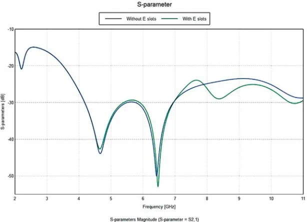
The simulated results are obtained using CADFEKO based on the dimensions given in Fig. 1. The simulated S-parameters (S12 or S21) of the ordinary SCA monopole antenna and SCA with E-shaped
slots are shown in Fig. 4. Compared to the ordinary antenna, it is seen that the E-shaped slot in the ordinary monopole antenna achieves high isolation.
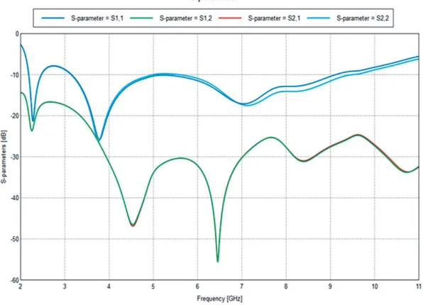
The simulated S12 or S21 of the antenna with and without narrow slots in the ground plane is
Figure 4. SimulatedS12 orS21 (with and without E-shaped slots).
Figure 5. SimulatedS12 orS21 (with and without ground slots).
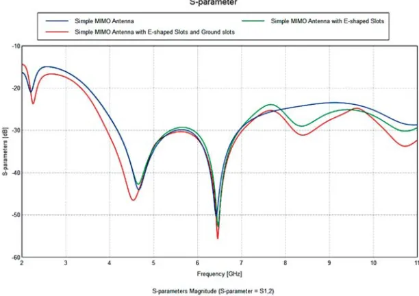
Figure 6 shows the comparison of different structures of the proposed antenna. Blue line shows the simple MIMO antenna. This antenna has low isolation compared to other two antennas. Green line indicates the simple MIMO antenna with an E-shaped slot. Red line indicates the proposed antenna.
The current distribution of proposed antenna at 3.5 GHz is shown in Fig. 7. The current is mainly concentrated on the edges of the radiating patch. As seen, the current flowing from port 1 to port 2 is blocked by the slot, and when port 1 is excited, the coupling current on another radiating patch is reduced significantly. The effect is the same as that from port 2 to port 1.
Figure 6. SimulatedS parameters of the various structures of the antenna.
Figure 7. Simulated current distribution of the proposed antenna at 3.5 GHz.
to cross-polarization shows directional radiation pattern in the opposite direction, whereas the co-polarization shows the same pattern as that of xoz and xoy of cross-polarization. It is seen that the co-polarization plays a predominant role in the plane.
The radiation pattern inxoyandxozis omnidirectional under co-polarization, and it is bidirectional in other directions and polarization. It can be visualized from the radiation pattern that the co-polar and cross-polar isolation at 4 GHz is found to be 5 dB in the horizontal (E) plane, i.e., yoz and 10 dB in the vertical (H) plane (xoz). The lower value inyoz is due to low co-polarization. But the difference is around 10 dB in xoz-plane at the frequencies of 4 and 6 GHz. It is seen that at the frequency of 8 GHz, the difference between co-polarization and cross-polarization levels is increased, due to the flow ofx-directed currents in the same direction. At 8 GHz, the co-polar and cross-polar isolation difference is found about 10 dB.
Table 1 shows the comparison of efficiency, VSWR, reflection coefficient, and transmission losses at different frequencies of the proposed QSCA.
(a)
(b)
(c)
Table 1. Performance analysis of QSCA.
Frequency 2.1 GHz 4 GHz 6.5 GHz
Efficiency (%) 81 84 76
VSWR 1.15 1.12 1.29
Reflection Co-efficient 0.0707 0.0652 0.126 Transmission loss (dB) 0.0205 0.0139 0.0932
Figure 9. Synthesizer output ofS11.
S11 S21
antenna. It is observed from Fig. 12 that S11 shows approximately a maximum of 2.5 dB difference
Figure 11. Comparison of S-parameters.
between the measured and simulated results at frequencies 2.1, 4.5, and 6.5 GHz. S21shows a variation
of 2.5 dB at the frequency of 4.5 GHz and 7 dB at the frequency of 6.5 GHz. It is understood from the literature that the antenna performance also depends on the fabrication. The mismatch in the results may be due to the insertion loss of SMA (Sub Miniature version A) connectors. SMA are semi-precision coaxial RF connectors developed in the 1960s as a minimal connector interface for coaxial cable with a screw-type coupling mechanism. The connector has a 50 Ω impedance.
4. CONCLUSION
A MIMO antenna with dimensions of 41×30×0.8 mm3 is proposed for UWB applications. It consists of two quasi-self complementary monopole antennas as the radiating patch on the top of the substrate. High isolation is obtained here by inserting an E-shaped slot in the radiating patch. To reduce the mutual coupling and further enhance the isolation, a narrow slot is added to the ground plane. The proposed antenna is tested using network synthesizer, and it is observed that the results almost match the simulation.
REFERENCES
1. Yang, L. and G. B. Giannakis, “Ultra-wideband communications: An idea whose time has come,” IEEE Signal Process. Mag., Vol. 21, No. 6, 26–54, 2004.
2. Fontana, R. J., “Recent system applications of short-pulse ultra-wideband (UWB) technology,” IEEE Transactions on Microwave Theory and Techniques, Vol. 52, No. 9, 2087–2104, 2004. 3. Zhu. F., et al., “Multiple band-notched UWB antenna with band-rejected elements integrated in
the elements integrated in the feed line,”IEEE Trans. Antennas Propag., Vol. 61, No. 8, 3952–3960, 2013.
4. Li, L., S. W. Cheung, and T. I. Yuk, “Compact MIMO antenna for portable devices in UWB applications,” IEEE Trans. Antennas Propag., Vol. 61, No. 8, 4257–4264, 2013.
5. Kang, T.-W., K.-L. Wong, and M.-F. Tu, “Internal mobile phone antenna array for LTE/WWAN and LTE MIMO operations,” Microwave Opt. Technol. Lett., Vol. 53, No. 7, 1569–1573, 2011. 6. Saraereh, O. A., C. J. Panagamuwa, and J. C. Vardaxoglu, “Low correlation multiple antenna
system for mobile phone applications using novel decoupling slots in ground plane,”Lough Borough Antennas and Propagation Conference (LAPC), 577–581, 2013.
7. Ban, Y., Z. Chen, Z. Chen, K. Kang, and J. Li, “Decoupled heptaband antenna array for WWAN/LTE smartphone applications,”IEEE Trans. Antennas Wireless Propag. Letters, Vol. 13, 999–1002, 2014.
8. Lai, S., Y. Li, and C. Tang, “A MIMO LTE antenna system with decoupling elements for smart phone application,”Proceedings of ISAP, 595–596, 2014.
9. Wong, K. and J. Lu, “3.6-GHz 10-antenna array for MIMO operation in the smartphone,” Microwave Opt. Technol. Lett., Vol. 57, No. 7, 1699–1704, 2015.
10. Chen, S. C., J. Y. Sze, and K. J. Chuang, “Isolation enhancement of small-size WLAN MIMO antenna array for laptop computer application,” Journal of Electromagnetic Waves and Applications, Vol. 31, No. 3, 323–334, 2017.
11. Liu, L., S. Cheung, and T. Yuk, “Compact MIMO antenna for portable devices in UWB applications,” IEEE Trans. Antennas Propag., Vol. 61, 4257–4264, 2013.
12. Zhang, S., B. K. Lau, A. Sunesson, and S. He, “Closely-packed UWB MIMO/diversity antenna with different patterns and polarizations for USB dongle applications,” IEEE Trans. Antennas Propag., Vol. 60, No. 9, 4372–4380, 2012.
18. Gao, P., et al., “Compact printed UWB diversity slot antenna with 5.5-GHz band-notched characteristics,” IEEE Antennas and Wireless Propagation Letters, Vol. 13, 376–379, 2014.
19. Li, J. F., Q. X. Chu, Z. H. Li, and X. X. Xia, “Compact dual band notched UWB MIMO antenna with high isolation,” IEEE Trans. Antennas Propag., Vol. 61, No. 9, 4759-4766, 2013.
20. Guo, L., S. Wang, X. D. Chen, and C. Parini, “A small printed quasi-self-complementary antenna for ultra wideband systems,” IEEE Antennas and Wireless Propagation Letters, Vol. 8, 554–557, 2009.