Abstract—In this paper, a hexagonal-shaped multiple-input multiple-output (MIMO) patch antenna is presented. It covers the S band (2–4 GHz), WLAN (2400–2480 MHz & 5150–5350/5725–5875 MHz), UWB (3.1–10.6 GHz), and X band (8–12 GHz) applications. The proposed structure is simulated and fabricated on an FR4 substrate with overall dimensions of 0.186λ0 ×0.373λ0 and separation of two
patches with a distance of 0.053λ0 (where λ0 is the wavelength at 2 GHz). The single UWB patch is
antenna derived from the triangular-shaped edge cuttings in the bottom of the rectangular patch antenna with a partial and defected ground. The proposed MIMO structure produces simulated results from 2 GHz to 13.3 GHz and measured results from 2.1 GHz to 12.9 GHz, with good agreement. The proposed structure resonates at 3.4 GHz, 5.8 GHz, 10.2 GHz, and 11.8 GHz. The isolation is improved to above 20 dB by placing an E-shaped tree structure and parasitic element in most of the band. The radiation efficiency and peak gain values are 78–94% and 1.4–6.6 dB, respectively. Diversity performance of the proposed structure is verified with low envelope correlation coefficient (ECC<0.04), high diversity gain (DG>9.985), and acceptable total active reflection coefficient (TARC<−10 dB) values.
1. INTRODUCTION
Nowadays, ultra-wideband (UWB) technology plays an indispensable role in wireless communications because of its data transmission at high speeds, high security, low cost, and low power consumption. For commercial applications of UWB systems and to avoid interference between the other bands, Federal Communications Commission (FCC) officially assigned an unlicensed band from 3.1 GHz to 10.6 GHz with−41.3 dBm/MHz radiated power [1, 2]. However due to signal fading in the multipath environment, the performance of UWB systems is degraded which leads to lesser efficiency in signal transmission and low-quality transmission.
The problem of UWB systems can be overcome by using MIMO technology. Transmitter and receiver use multiple antennas to improve the quality of transmission, system capacity, high data rate, and reliability [3, 4]. Thus, the problem of multipath fading in UWB systems can be overcome by MIMO technology. The combination of a UWB system and MIMO technology plays a very significant role in the present wireless communication systems due to the large bandwidth of 7.5 GHz. In MIMO technology, antenna elements are arranged side by side with less distance. Due to the low space between antenna elements, there would be a chance of coupling between them. This coupling arises mainly due to radiation in free space, surface currents on metals, and surface waves in the dielectric medium [5]. Consequently, mutual coupling affects signal transmission and eventually degrades the overall system performance. A variety of techniques are in practice to reduce the effect of mutual coupling like polarization diversity, defected ground structure (DGS), electromagnetic bandgap structure (EBG), metamaterials, neutralization lines, and by placing parasitic elements between antenna elements.
Received 10 October 2019, Accepted 26 November 2019, Scheduled 16 December 2019
* Corresponding author: Tathababu Addepalli ([email protected]).
1 Department of ECE, JNTUA, Ananthapur, A.P, India. 2 Antenna Research Lab, Sree Vidyanikethan Engineering College,
two elements of a MIMO antenna for coupling reduction [12]. A rectangle-shaped MIMO antenna with bending feed and isolation is enhanced by placing ground strips [13].
Radiating elements of a two-element antenna of size 48×48 mm2 are placed in orthogonal to each other for isolation enhancement up to 15 dB [14]. Isolation enhancement of a printed UWB MIMO antenna of size 48×110 mm2 is 20 dB [15]. Isolation is improved between two circular shaped
antennas using resistive loading, which is above 25 dB [16]. Meandering lines are placed between two PIFA antennas for coupling reduction, and it gives isolation above 15 dB [17]. A two-port Vivaldi antenna has the isolation above 16 dB for the entire band using T shaped slot in the ground plane [18]. The antiparallel arrangement of a half-circular-shaped MIMO antenna is of size 35×50 mm2 with isolation enhancement using a fence type decoupling structure [19]. A 0.31λ0 ×0.41λ0 size printed
UWB antenna with reduction of coupling using decoupling network, and it operates from 3.1 to 10.6 GHz [20]. An inverted T-shaped slot is introduced between closely spaced UWB slot-antennas for isolation improvement of size 40×60 mm2 [21]. A 40×40 mm2 size dual-polarized MIMO antenna with isolation improvement uses DGS for ultra-wideband applications [22]. A U-shaped slotted fractal MIMO antenna has the isolation of 22 dB [23]. An anti-parallel arrangement of two hexagon-shaped UWB antennas with CPW-feed operate with a bandwidth of 3–12 GHz [24]. All the decoupling networks and orthogonal arrangement antenna elements give isolation of 15 dB or more for quality of transmission. In this paper, a MIMO patch antenna with isolation is presented. The overall size of proposed structure is 0.186λ0×0.373λ0 (28×56 mm2), and it is simulated and fabricated on a widely available
FR4 substrate of dielectric constant 4.4 and loss tangent 0.02. The two antenna elements are separated by a distance of 0.053λ0 (8 mm). The top layer of the proposed structure is fed by two 50 Ω microstrip
lines. The isolation between the two elements is below 14 dB. To enhance the isolation, an E-shaped tree structure and s parasitic element are placed between them. It is improved to higher than 20 dB (90%) in most of the band, except 2–3.2 GHz (17 dB). The remaining paper is organized as follows. In Section 2, design procedure and analysis of the proposed structure are presented. In Section 3, simulated and measured results are discussed. In Section 4, diversity performance parameters ECC, DG, and TARC values are discussed. Section 5 provides comparison table and discussions, and conclusion is drawn in Section 6.
2. PROPOSED STRUCTURE AND ANALYSIS 2.1. Antenna Design
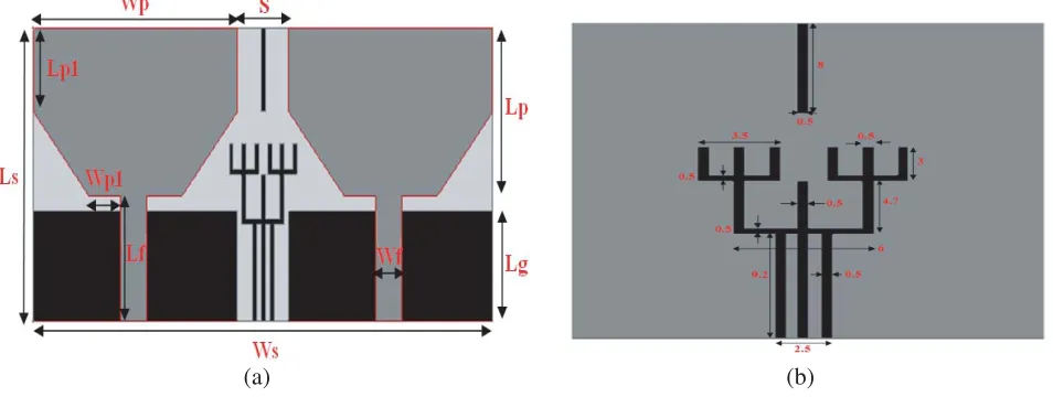
The proposed structure design and parameters are illustrated in Figure 1. The proposed structure consists of two hexagon-shaped patch antennas that are separated by a distance of 8 mm with a partial ground plane and DGS. By placing an E-shaped tree structure and a parasitic element between the antenna elements, isolation is improved to 17.5 dB from 12 dB in a lower band (2–3.2 GHz) and 20 dB from 14 dB in remaining band. The proposed structure is designed and simulated by using Ansoft HFSS simulation software. TheS-parameter results are verified by an Agilent N5230A vector network analyzer. The optimized values of the proposed structure are listed in Table 1.
2.2. Step by Step Evolution Process
(a) (b)
Figure 1. (a) Geometry of proposed structure with ground; (b) Dimensions of E-Shaped tree structure and parasitic element.
Table 1. Proposed structure dimensions.
Ls Ws Lp Wp Lg
28 58 16 24 10.5
Lp1 Wp1 Lf Wf S
8 3.75 12 3.5 8
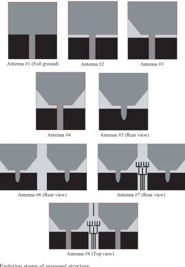
with respect to patch dimensions, antenna #1 should resonate at 4 GHz, but it actually resonate at 6 GHz due to the reduction of ground dimensions. Actually the ground dimensions are equal to the substrate dimensions, and their lengths and widths will depend on patch length and width, and the height of the substrate, i.e., Lg= 6h+Land W g= 6h+W, whereas ‘Lg’ and ‘W g’ are ground length and width, respectively; ‘L’ and ‘W’ are patch dimensions, and ‘h’ is height of the substrate. However, the ground width is reduced to the patch width, and also the length of the ground is adjusted for compactness. Hence, it resonates at 6 GHz. In stage two, antenna #2 resonates at 4 GHz and 12.3 GHz due to the partial ground plane. In stage three, optimized values of a right angle triangle-shaped patch are subtracted from the left side bottom of the patch antenna for impedance matching, resulting in obtaining 3–6.2 GHz and 11.5–13 GHz bandwidths.
Later, another right angle triangle-shaped patch is removed from the right side bottom of the patch antenna in stage four. It improves the bandwidth of both the dual bands. In stage five, an ellipse-shaped curve is removed from the center of the partial ground plane for bandwidth enhancement. It gives an impedance bandwidth of 2.8–13.4 GHz (S11<−10 dB), which is the required ultra wideband.
In stage six, another same antenna is placed at a distance of 0.053λ0, which causes mutual coupling
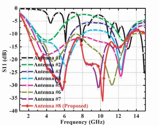
between the antenna elements, above 14 dB, but it is not sufficient for MIMO systems. To reduce the mutual coupling, placing an optimized E-shaped tree structure between antenna elements improves the isolation to above 20 dB in most of the band except a small band, in the seventh stage. In stage eight, a rectangular strip of size 8×0.5 mm2 is placed between them, which increases the isolation at high frequencies. The process of the return loss changes from the basic antenna to all the antenna stages is described in Figure 3.
W = Co 2fr
2
εr+ 1 (1)
Antenna #1 (Full ground) Antenna #2 Antenna #3
Antenna #4 Antenna #5 (Rear view)
Antenna #6 (Rear view) Antenna #7 (Rear view)
Antenna #8 (Top view)
Figure 2. Evolution stages of proposed structure.
and ‘W’ the width of the patch.
εreff = εr+ 1
2 +
εr−1 2
1 + 12 h W
−1 2
, W
h >1 (2)
ΔL
h = 0.412
(εreff + 0.3)
W
h + 0.264
(εreff −0.258)
W
h + 0.8
Figure 3. Simulated ‘S11’ values of antenna evolution stages.
’εreff’ is the effective relative permittivity, and ‘h’ is the height of the substrate.
L= Co
2fr√εreff −2ΔL (4)
‘ΔL’ is the increased length of the patch due to fringing fields, and ‘L’ is the length of the patch. The two antenna elements are placed at a distance of 0.053λ0, because small spacing coupling
is introduced which is above 12 dB. Isolation is improved at higher frequencies because three small strips are placed between the elements. E-shaped patch is added to the three strips, and isolation is improved to above 13 dB for the entire band. U-shaped patches are added to the outer edges of the E-shaped patch, then isolation is improved to above 15 dB from 3.35 GHz to 13.3 GHz and maintains above 15.5 dB in remaining band. Later, small strips are added to the middle of the U shaped strip, and the resultant structure is an E-shaped tree structure. After placing the tree structure, isolation is improved from 15.5 dB to 17.5 dB at lower band, i.e., 2–3.5 GHz and 18 dB to 20 dB in remaining band. Later, a rectangular strip with a small elemental length and width is placed in the top position of the ground plane. It affects the isolation at higher frequencies from 9 GHz to 13.3 GHz, which is improved to above 25 dB from 20 dB, and the remaining bandwidth is the same. Figure 4 describes S21 values of
the proposed structure at various stages.
2.3. Surface Current Distributions and Analysis
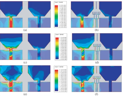
Figure 5 shows currents distributions of the proposed structure at various resonant frequencies. From Figures 5(a) & (b) it is observed that after placing a tree structure and patch element, there is still a small effect on the other antenna. Because at 3.4 GHz the isolation is 18 dB, before that it is 15 dB. Due to the small variation from 15 dB to 18 dB, there is a small coupling effect, which is uncountable. At 5.8 GHz, the isolation improves to 22.5 dB from 16 dB, hence little coupling is observed between them in Figures 5(c) and 5(d). Figures 5(e) and 5(f) show that the isolation improves only at higher frequencies because of small elemental strip length, which improves to 25 dB from 20 dB. From all figures, it is observed that at higher frequencies, only strip stops the electromagnetic energy, and the remaining is not affected because of small elemental length.
2.4. Parametric Analysis
Figure 4. Simulated ‘S21’ values of antenna evolution stages.
(a) (b)
(c) (d)
(e) (f)
Figure 5. Surface current distribution of proposed structure when Port1 excited: (a) & (b) at 3.4 GHz; (c) & (d) at 5.8 GHz and (e) & (f) at 10.2 GHz.
(a) (b)
(c) (d)
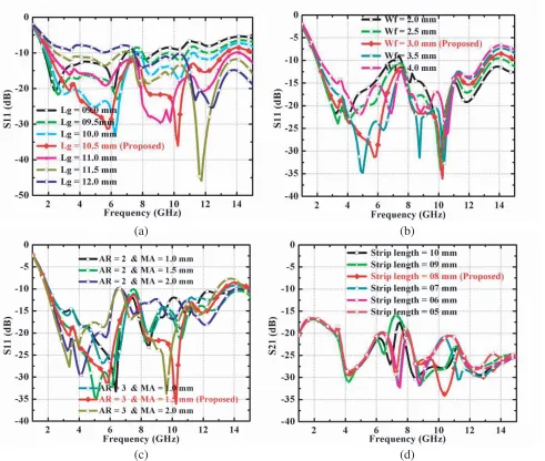
Figure 6. (a) Parametric study on ground length; (b) Parametric study on feed width; (c) Parametric study on elliptical cutting in ground plane and (d) parametric study on strip length.
in Figure 6(b). Figure 6(c) describes the parametric study on the partial ground with the defected ground. An ellipse-shaped patch with different axial ratios (ARs) and major axes (MAs) is removed from the partial ground plane; it will affect the impedance matching then giving the required bandwidth. AR = 3 mm and MA = 1.5 mm are required parameters for the proposed structure. A small rectangular strip is placed in the position of the top ground plane with various values and corresponding isolation improvement at higher frequencies shown in Figure 6(d).
3. SIMULATED AND MEASURED RESULTS 3.1. Impedance Performance
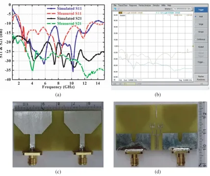
The proposed structure is fabricated on a low cost, widely available FR4 substrate, tested, and verified practically. The measured results are almost the same as the simulated ones. Due to tolerances in soldering and fabrication, a small deviation occurs. Figure 7(a) shows simulated and measured S11 &
S21 values. A photograph of S11 and S21 values of the proposed structure is shown in Figure 7(b).
(a) (b)
(c) (d)
Figure 7. (a) Simulated and measured S11 &S21 values of proposed structure; (b) Photograph of S
parameter values from VNA; (c) Proposed structure front view and (d) proposed structure rare view.
2.9 GHz, but in simulation it is 20 dB (90% band) except 2–3.2 GHz. Figures 7(c) & (d) show top and rare views of the proposed structure. Table 2 describes the performance comparison of simulated values with measured values, and finds they are in good agreement.
Table 2. Comparison of simulated values with measured values.
Antenna parameter Impedance bandwidth (GHz) Isolation (dB) Resonant frequencies (GHz) S11 Value (dB) S21 Value (dB) Simulated 2–13.3 2–3.2 GHz (≥17 dB) 3.3–13.3 GHz
(≥20 dB)
03.4 05.8 10.2 11.8
−20.6 −31.7 −36.9 −15.1
−19.0 −21.6 −33.4 −27.3
Measured 2.1–12.9
2.1–2.9 GHz (≥18 dB) 3–12.9 GHz
(≥25 dB)
03.1 05.2 08.0 11.8
−20.6 −14.0 −28.2 −17.8
(a) (b)
(c) (d)
Figure 8. (a) E and H field radiation patterns at 3.4 GHz; (b) E and H field radiation patterns at 5.8 GHz; (c) E and H field radiation patterns at 10.2 GHz and (d) Photograph of proposed structure from anechoic chamber.
3.2. Radiation Performance
The graphical representation of EM energy from the radiating element is nothing but a radiation pattern. The measurement of radiation patterns is carried in an anechoic chamber, with a horn antenna as a reference antenna and the proposed antenna under testing. Figures 8(a), (b) and (c) show the simulated and measured 2-D representations of E and H fields at 3.4 GHz, 5.8 GHz, and 10.2 GHz. At 3.4 and 5.8 GHz, E and H are perfect bidirectional and omnidirectional radiation patterns, but at 10.2 GHz the patterns of E and H fields are disturbed due to higher-order modes. At higher frequencies, EM energy is distributed to all the modes as a result, and the patterns are not bidirectional and omnidirectional. A photograph of the proposed structure in the anechoic chamber is shown in Figure 8(d). The measured results almost follow the simulated ones.
Figure 9. Simulation values of radiation efficiency and peak gain.
4. DIVERSITY PERFORMANCE
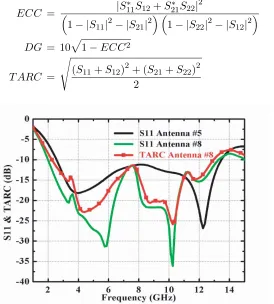
ECC, DG, and TARC metrics must be taken into account for checking the diversity performance of any MIMO antenna. ECC values define the coupling between antenna elements [26]. If it is zero, both elements are isolated to each other. If it is one, there will be more coupling between elements, hence the range of ECC is zero to one. Practical acceptable value of ECC for MIMO systems is less than 0.5. The ECC value of proposed structure is less than 0.04. The ECC can be measured usingS parameters which is represented in Equation (5) [27]. Diversity gain is measured using ECC values, and the relation between ECC and DG is represented in Equation (6). The proposed structure gives DG values above 9.985 dB. ECC and DG values are represented in Figure 10.
Figure 10. Simulated ECC and DG values of proposed structure.
S11 value is enough for the single radiating element for how much signal power of antenna will
ECC = |S ∗
11S12+S∗21S22|2
1− |S11|2− |S21|2 1− |S22|2− |S12|2
(5)
DG = 10 1−ECC2 (6)
T ARC =
(S11+S12)2+ (S21+S22)2
2 (7)
Figure 11. Simulated S11 & TARC values of Antenna #5 and proposed structure.
5. PERFORMANCE COMPARISON WITH OTHER STRUCTURES
The parameters’ performances of the proposed structure with other systems in terms of their size, shape, impedance bandwidth, isolation, diversity performance parameters, and applications are depicted in Table 3 [6–9, 14–24, 26, 31] are considered from the references. The proposed structure gives good impedance bandwidth from 2–13.3 GHz (S11 < −10 dB), isolation S21 > 17.5 dB for the entire band,
X-band
Ref. [6] 26×40 3.5 Rectangular 3.1–10.6 >15 0.9–6.5 >80 0.2 UWB
Ref. [7] 47×93 4.4 Circular 3.1–10.6 >31 3.5 >70 −21 dB UWB
Ref. [8] 58×58 3.6 Semi
circular 2.8–11 >14 2.2 >70 0.02 UWB
Ref. [9] 32×32 4.4 Rectangular 3.1–10.6 >15 1.7–4.2 >60 0.02 UWB
Ref. [14] 48×48 4.4 Rectangular 2.5–12 >15 3 NA 0.005 UWB
Ref. [15] 48×110 4.4 Truncated
square 2.3–7.7 >20 4.4 NA NA
WLAN,
Lower
UWB
Ref. [16] 35×36 2.2 Circular 3.0–9.0 >17 5.5 >88 0.025 UWB
Ref. [17] 61×65 3.5 PIFA 1.56–2.71 &
4.82–5.9 >15 NA >80 0.04 WLAN
Ref. [18] 26×26 3.5 Vivaldi 2.9–11.6 >16 0–6 NA 0.02 UWB
Ref. [19] 35×50 4.3 Half
circular 3.0–11 >25 4–6 >80 0.004 UWB
Ref. [20] 30×40 4.4 Rectangular 3.1–10.6 >15 NA >80 0.05 UWB
Ref. [21] 40×60 4.4 Slot 3.2–11 >20 4 >90 0.06 UWB
Ref. [22] 40×40 4.4 Pentagonal 3.2–11 >15 4 >70 NA UWB
Ref. [23] 26×35 6 Fractal 2.0–10.6 >22 NA NA 0.2 UWB
Ref. [24] 45×25 4.4 Hexagonal
ring 3.0–12 >15 1.8–5.4 >70 0.2 UWB
Ref. [26] 22×26 4.4 Trident 3.1–10.6 >20 2–6 >75 0.03 UWB
Ref. [31] 40×37.5 4.4 Rectangular 3.2–11 >15 NA NA 0.12 UWB
6. CONCLUSION
A hexagon-shaped MIMO antenna is simulated and fabricated on an FR4 substrate with dielectric constant 4.4 and verified practically. The proposed structure gives an impedance bandwidth of 2– 13.3 GHz and good isolation, which is higher than 20 dB in most of the band. Good diversity performance values (ECC<0.04, DG>9.985, and TARC<−10 dB for entire band) are achieved. Measured values are in good agreement with simulated values. It covers S-band, WLAN, UWB, and X- band applications.
ACKNOWLEDGMENT
5. Nadeem, I. and D.-Y. Choi, “Study on mutual coupling reduction technique for mimo antennas,”
IEEE Access, Vol. 7, 563–586, 2019.
6. Liu, L., S. W. Cheung, and T. I. Yuk, “Compact MIMO antenna for portable devices in UWB applications,” IEEE Transactions on Antennas and Propagation, Vol. 61, No. 8, 4257–4264, 2013. 7. Radhi, A. H., R. Nilavalan, Y. Wang, H. S. Al-Raweshidy, A. A. Eltokhy, and N. A. Aziz, “Mutual coupling reduction with a wideband planar decoupling structure for UWB-MIMO antennas,”
International Journal of Microwave and Wireless Technologies, Vol. 10, No. 10, 1143–1154, 2018. 8. Chacko, B. P., G. Augustin, and T. A. Denidni, “Uniplanar slot antenna for ultra wide band
polarization — diversity applications,” IEEE Antennas and Wireless Propagation Letters, Vol. 12, 88–91, 2013.
9. Ren, J., W. Hu, Y. Yin, and R. Fan, “Compact printed MIMO antenna for UWB applications,”
IEEE Antennas and Wireless Propagation Letters, Vol. 13, 1517–1520, 2014.
10. Naderia, M., F. B. Zarrabib, F. S. Jafaric, and S. Ebrahimid, “Fractal EBG structure for shielding and reducing the mutual coupling in microstrip patch antenna array,” International Journal of Electronics and Communications, Vol. 93, 261–267, 2018.
11. Ouahabi, M. E., A. Zakriti, M. Essaaidi, A. Dkiouak, and H. Elftouh, “A miniaturized dual-band MIMO antenna with low mutual coupling for wireless applications,” Progress In Electromagnetics Research C, Vol. 93, 93–101, 2019.
12. Veeramani, A., A. S. Arezomand, J. Vijayakrishnan, and F. B. Zarrabi, “Compact S-shaped EBG structures for reduction of mutual coupling,” IEEE, Fifth International Conference on Advanced Computing& Communication Technologies, 21–25, 2015.
13. Babashah, H., H. R. Hassani, and S. Mohammad-Ali-Nezhad, “A compact UWB printed monopole MIMO antenna with mutual coupling reduction,”Progress In Electromagnetics Research C, Vol. 91, 55–67, 2019.
14. Gao, P., S. He, X. Wei, Z. Xu, N. Wang, and Y. Zheng, “Compact printed UWB diversity slot antenna with 5.5 GHz band-notched characteristics,” IEEE Antennas and Wireless Propagation Letters, Vol. 13, 376–379, 2014.
15. Wong, K. L., S. W. Su, and Y. L. Kuo, “A printed ultra-wideband diversity monopole antenna,”
Microwave and Optical Technology Letters, Vol. 38, No. 4, 257–259, 2003.
16. Park, J.-D., M. U. Rahman, and H. N. Chen, “Isolation enhancement of wide-band MIMO array antennas utilizing resistive loading,”IEEE Access, Vol. 7, 81029–81026, 2019.
17. Li, Q., M. Abdullah, and X. Chen, “Defected ground structure loaded with meandered lines for decoupling of dual-band antenna,” Journal of Electromagnetic Waves and Applications, Vol. 33, No. 13, 1764–1775, 2019.
18. Li, Z., C. Yin, and X. Zhu, “Compact UWB MIMO vivaldi antenna with dual band-notched characteristics,” IEEE Access, Vol. 7, 38696–38701, 2019.
WIMAX,”IETE Journal of Research, 1–8, 2019.
24. Mathur, R. and S. Dwari, “Compact CPW-fed ultra wide band MIMO antenna using hexagonal ring monopole antenna elements,” International Journal of Electronics and Communications, Vol. 93, 1–6, 2018.
25. Balanis, C. A., Antenna Theory Analysis and Design, 3rd Edition, a John Wiley & Sons, Inc., Publication, Copyright 2005 by John Wiley & Sons, Inc. All rights reserved.
26. Jetti, C. R. and V. R. Nandanavanam, “Trident-shape strip loaded dual band-notched UWB MIMO antenna for portable device applications,” International Journal of Electronics and Communications, Vol. 83, 11–21, 2018.
27. Jetti, C. R. and V. R. Nandanavanam, “A very compact MIMO antenna with triple band-notch function for portable UWB systems,” Progress In Electromagnetics Research C, Vol. 82, 13–27, 2018.
28. Chandel, R. and A. K. Gautam, “Design and packaging of an eye-shaped multiple-input-multiple-output antenna with high isolation for wireless UWB applications,” IEEE Transactions on Components, Packaging and Manufacturing Technology, Vol. 8, No. 4, 635–642, 2018.
29. Malviya, L. and K. Machavaram, “MIMO antennas with diversity and mutual coupling reduction techniques: A review,” International Journal of Microwave and Wireless Technologies, Vol. 9, No. 8, 1763–1780, 2017.
30. Chae, S. H., W. I. Kawk, S. Park, and K. Lee, “Analysis of mutual coupling in MIMO antenna array by TARC calculation,” Asia-Pacific Microwave Conference, 2090–2093, 2006.
31. Jafri, S. I., R. Saleem, M. F. Shafique, and A. K. Brown, “Compact reconfigurable multiple-input-multiple-output antenna for ultra wideband applications,” IET Microwaves, Antennas &