328 | P a g e
STUDY OF SLOTTED MICROSTRIP PATCH ANTENNA
FOR WIRELESS COMMUNICATION
B.V.Devipriya
1, V.Dinesh
2, J.Vijayalakshmi
31
PG Scholar,
2,3Assistant Professor, Department of Electronics and Communication Engineering,
Kongu Engineering College, Perundurai, Erode, Tamilnadu (India)
ABSTRACT
In this paper U-Slot microstrip patch antenna, uses probe-fed excitation mainly in order to improve the directivity
and gain of the antenna. The position of the probefeed is optimized which will further enhance return loss below
-10 dB and to improve the impedance bandwidth. This paper also discuss about the types and distribution of
metamaterial and there composite structure. In general metamaterial are the material that do not endure in nature
and they have different optical properties. A metamaterial exhibits negative refraction when the permittivity ( ) and
permeability (µ) values are negative.
In the proposed work the metamaterial unit cell structure is designed with the concept of GRIN lens. The array of
lens structure is designed for beam steering application. When the array of GRIN lens structure is placed in antenna
it gives good directivity. The lens designed plays a dynamic role in wireless communication.
Keywords: Microstripantennas, Metamaterial (MTM), GRIN lens
I INTRODUCTION
Antenna is a vital element of any wireless communication system for uninterrupted transmission and reception. As
well as the development of miniaturized handheld electronic system for endless communication, the antennas are the
major requirement with minimum loss. Antennas are used in communication with a missile or over jagged mountain
terrain where cables are luxurious.
Microstrip antennas are used mainly due to their feather weight, conformability and economical in terms of cost.
These antennas can be combined with strip-line feed networks and active devices. This is moderatelyan
innovativesector of antenna engineering. The radiation featuresof microstrip structures have been recognizedever
since the mid 1950’s. A major issue for moderndevelopments of microstrip antennas is the existing revolution in
electronic circuitminiaturization brought about by growths in large scale integration.
In this paper the rectangular patch is loaded with U-slot antenna is designed for wireless communication. The slot
329 | P a g e
dielectric material substrate which has a dielectric constant of 4.4 loss tangent of 0.02 and with a height of 7.62mmis used. The antenna parameters such as radiation pattern, directivity, return loss, VSWR and bandwidth of the
proposed antenna are simulated using HFSS 14.
Metamaterials are the artificial materials which are reformed from the materials that occur in nature. These
metamaterials have electromagnetic properties. According to David R. Smith Metamaterial can be referred as any
material that is consists of periodic, macroscopic structures so as to accomplish a preferred electromagnetic
response.
Applications of negative index metamaterial are miniature antennas, perfect lens, dual band characteristic and
enhancement of directivity. Metamaterials have been utilized in order to increase the beam scanning range of
antenna arrays. These antenna plays a most importantpart in communication links and surveillance sensors.
II U SLOT MICROSTRIP PATCH ANTENNA DESIGN
The antenna is design with the operating frequency of 3.35 GHz. The slot is introduced for the betterment of
bandwidth, good return loss and radiation characteristics as requiredforwireless applications. The antenna is
designedwith the dimension of 50 X 40 mm. The substrate used in this layout is dielectric material FR4 with a
constant 4.4. Coaxial probe feeding is used to moderate the dimensionsof the antenna. The dimensions of the
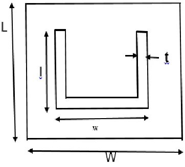
antenna is given in the figure: 1.
Fig. 1. U slot patch antenna with geometrical dimension L=40, W=50, l=16, w=13, t= 0.02 (units:
mm)
Slots are introduced in the patch to improve the polarization. The U slot used in the microstrip patch antenna helps
330 | P a g e
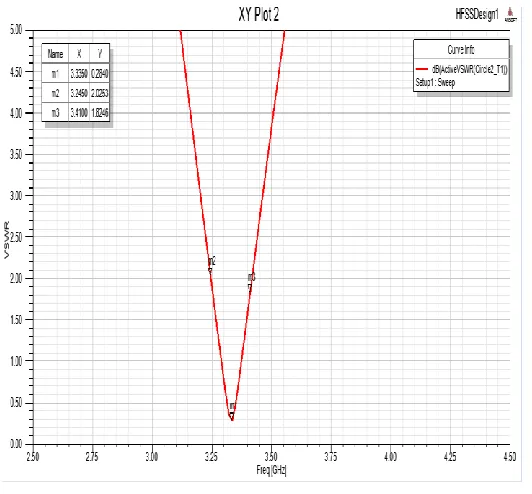
Fig. 2. Return loss vs frequency
Higher value of return loss shows larger power being transmitted by antenna which results in higher gain of
antenna.Patch antenna with U slot exhibits return loss of -34.15 dB at exactly 3.35 GHz is shown in the figure:2.
331 | P a g e
VSWR is less than 2 over the operational bandwidth which show a good impedance matching of the antenna withthe transmission line. In figure:3 VSWR graph describes the power reflected from the antenna.
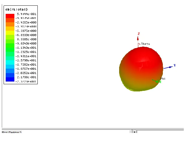
Fig. 4. Gain of microstrip patch antenna.
The radiation pattern describes the dissimilarity of radiated power over long distances in dissimilar directions in
space. Figure:4 – shows that the simulated antenna radiates with a gain of 5.44 dB.
III GRIN METAMATERIAL LENS STRUCTURE
GRIN lens is designed according to the Fermat’s principle. This type of lens is designed to convert spherical waves
into plane waves. GRIN metamaterial lens is constructed with square blocks of unit cell. Substrate has a split ring
resonator on the top and the microwave varactor diode is added between the two arms of the squaring. The LC
resonance of the SRR is determined by the magnetic field. The resonance frequency depends mainly on the lumped
parameters, which varies the reverse bias voltage.
In the design F4B is selected as the dielectric substrate and has the relative permittivity of 2.65 and thickness is
about 0.2mm. Feeding network is placed on the bottom of the substrate and plated through holes in order to link the
feeding network and the pins. The varactor diode in the unit cell chooses the commercial varactor diode
SMV1231-079lF from sky work solution, whose capacitance varies from 2.3 to 0.46 pF when reverse bias voltage changes
332 | P a g e
The lens changes the incoming beam to different forms when different sets of bias voltage are applied. The biasmaterial lens is added the spherical waves is transformed into planes waves. The dimensions of the unit cell structure
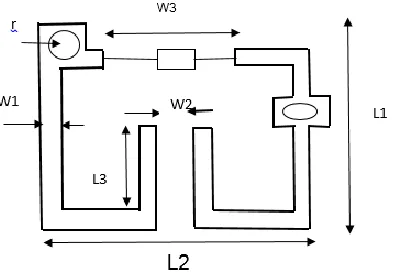
is shown in the figure: 5.
Fig. 5. Unit cell structure of GRIN lens with dimension L1=3.6, L2=2.4, L3=1.3, W1=0.15, W2=0.2,
W3=1.2, r=0.13 (units: mm)
GRIN metamaterial lens designed to convert cylindrical waves or else spherical waves into planar waves. It
alsoincreases the directivity.
The GRIN lens is designed in such a manner so that it can able to change the incoming beam to different forms
depending upon the bias voltage that is applied. Besides from beam steering application the GRIN lens can also be
designed to generate conical wave forms which will realize pseudo Bessel beam. The reflection and the transmission
coefficient of the unit cell differs depending upon the reverse bias voltage.
The metamaterial GRIN lens enhance the matching properties and the radiation properties. The simulated s
parameter will results in broadband properties. The result for return loss will be simulated for the wireless
communication applications using the metamaterial lens.
IV CONCLUSION
In the proposed design it is concluded that the U slot probe feed requires minimal optimization for realizing wide
band performance. The antenna designed has the efficiency 88%.
The metamaterial lens is designed for beam steering application. The designed GRIN lens also works for scanning
antenna. The lens transforms the spherical waveform into plane waveform.
The alignment of metamaterial unit cell is designed with the help of unit cell structure. The aligment of metamaterial
333 | P a g e
steer a beam with metamaterial lens structure. As a result it changes the direction of the main lobe of the radiationpattern.
REFERENCES
[1]R.A.Shelby, D. R.Smith, and S. Schultz, "Experimental verification of a negative index of refraction," Science,
vol. 292, no. 5514, pp. 77-79, 2001.
[2] T. J. Cui, D. Smith, and R. Liu, Metamaterials: theory, design, and applications, Springer, 2009.
[3]R. Liu, C. Ji, J. Mock, J. Chin, T. Cui, and D. Smith, “Broadbandground-plane cloak,” Science, vol. 323, no. 5912, pp. 366–369, 2009.
[4]J. Valentine, J. Li, T. Zentgraf, G. Bartal, and X. Zhang, “An opticalcloak made of dielectrics,” Nature materials, vol. 8, no. 7, pp. 568–571,2009.
[5] H. F. Ma and T. J. Cui, “Three-dimensional broadband groundplanecloak made of metamaterials,” Nature communications,vol. 1, p. 21, 2010.
[6] D. Smith, J. Mock, A. Starr, and D. Schurig, “Gradientindexmetamaterials,” Physical Review E, vol. 71, no. 3, p.036609, 2005.
[7]H. F. Ma, X. Chen, H. S. Xu, X. M. Yang, W. X. Jiang, and T.J.Cui, “Experiments on high-performance
beam-scanningantennas made of gradient-index metamaterials,” AppliedPhysics Letters, vol. 95, no. 9, p. 094107,
2009.
[8] N. Kundtz and D. R. Smith, “Extreme-angle broadbandmetamateriallens,” Nature materials, vol. 9, no. 2, pp. 129–132,2010.
[9] H. Hyunh and K. F. Lee, “Single-layer single-patch wideband microstrip antenna,” IET Electronic Letters, vol. 31, no. 16, pp. 1310–1312, 1995.
[10]A. A. Deshmukh and K. P. Ray, “Analysis of Broadband Variations of U-Slot cut Rectangular
MicrostripAntennas,”IEEE Antennas Propag. Mag., vol. 57, no. 2, pp. 181–193, April 2015.
[11] S. Costanzo and A. Costanzo, “Compact MUSA: Modified U-Slot Patch Antenna with Reduced
Cross-Polarization,”IEEE Antennas Propag. Mag., vol. 57, no. 3, pp. 71–80, June 2015.
[12]V. Natarajan and D. Chatterjee, “An Empirical Approach for Design of Wideband, Probe-fed, U-Slot,
Microstrip Patch Antennas on Single-Layer, Infinite, Grounded Substrates,”ACES Journal, vol. 18, no. 3, pp.
191–200, November 2003.
[13] J. Chalas, K. Sertel, and J. L. Volakis, “Computation of Q limits for Arbitrary-Shaped Antennas using Characteristics Modes,” Proc. IEEE Intl. Symp. Antennas Propag., pp. 772–774, 2011.
334 | P a g e
[15] Y. Chen and C. Wang, “Charcteristic Mode Based Improvement of Circularly Polarized U-Slot and E-Shaped
Patch Antennas,”IEEE Antennas and Propagation Letters, vol. 11, pp. 283–290, 2012.
[16] E. A. Daviu and M. C. Fabres,“Modal Analysis and Design of Bandnotched UWB Planar Monopole
Antennas,”IEEE Trans. Antennas. Propag., vol. 58, no. 5, pp. 1457–1467, May 2010.
[17] M. Fabres, E. Daviu, A. Nogueria, and M. Bataller, “The Theory of Characteristic Modes Revisited: A Contribution to the Design of Antennas for Modern Applications,” IEEE Antennas and Propagation Magazine,