HIGH PERFORMANCE ANTENNA ARRAY FOR 5
thGENERATION
WIRELESS COMMUNICATION SYSTEMS
Esua Ekpo
1+Umoren
Mfonobong Anthony2
1,2Department of Electrical/Electronics Engineering, University of Uyo, Uyo,
Nigeria.
(+ Corresponding author)
ABSTRACT
Article History Received: 13 June 2019 Revised: 19 July 2019 Accepted: 26 August 2019 Published: 16 October 2019
Keyword
s
PIFA Array Bandwidth Antenna Microstrip Beamforming Beamwidth Beam steering Dielectric.In this paper, a probe fed PIFA square array antenna is designed for the fifth generation (5G) wireless applications in EU countries with an allocated frequency band of 24.25GHz - 27.5GHz. The array designed is made up of 16 elements arranged in a 4x4 matrix form, this makes it easily integrated into very portable mobile devices. An impedance bandwidth of 12.5% ranging from 24.25GHz - 27.5GHz was achieved and measured, with each element having a reflection coefficient of less than -15dB and a worse case 14dB mutual coupling. With a uniform amplitude and no inter element phase difference, a maximum broadside gain of about 16.71dB is obtained with an SLL(Side Lobe Level) of 12dB and a 3dB beamwidth of 30 deg. Scanning the main beam to 48 deg in the E-plane (y-z plane) the broadside gain reduces to 14.46dB with a phase difference of 150 deg per column element and an SLL of 6.86dB still maintain a good beam focus of 30 deg 3dB beamwidth. These good characteristics renders this antenna a good candidate to be deployed for 5G mobile applications.
Contribution/ Originality:
This study contributes to the existing literature of works on the design of high performance antenna arrays for millimeter wave 5G frequency bands, having the capability of adaptive beam forming and steering, finding application in mobile and portable devices at a relatively low cost.1. INTRODUCTION
In modern communication systems the explosive growth in demand for wireless broadband that can carry video and other content-rich services, and the Internet of Things (IoT), where large numbers of smart devices communicate over the Internet has put a high demand on the speed and performance of existing mobile communication network, which has continued to evolve from one generation to another, from 2G(400Mhz - 900Mhz) to 4G(0.9GHz - 2.6 GHz), and currently the development of the 5th Generation wireless systems to achieve these high performance requirements, 5G will provide extreme broadband speed, ultra low latency, and ultra reliable web connectivity [1]. Higher data rates (multi-Gbps) drive the need for greater bandwidth systems, and the available bandwidth in the spectrum up through 6 GHz is not sufficient to satisfy these requirements. (For reference, current cellular operation is below 3 GHz.) This has moved the target operating frequency bands up into the millimeter wave range for the next generation of wireless communication systems. This frequency ranges from 3.3 - 6 GHz and 24 - 39 GHz as specified by the 3rd Generation Partnership Project (3GPP) in Release 15 [2].
Journal of Asian Scientific Research
ISSN(e):
2223-1331 ISSN(p):
2226-5724
DOI: 10.18488/journal.2.2019.99.140.150 Vol. 9, No. 9, 140-150.
This increase in the frequency of communication and the miniaturisation of mobile communication devices antennas has resulted in the high directivity of communication radio waves, in antenna design at high frequencies, it is not practical to make use of omni-directional antennas, due to their low efficiencies and performance at high frequencies, this leads to the need to design highly directional antennas for this application, also signal path and propagation challenges associated with operating at these frequencies also increases. For example, the attenuation due to gas absorption for a 60-GHz waveform is more than 10 dB/km, while a 700-MHz waveform experiences an attenuation on the order of 0.01 dB/km. A problem therefore arises from the use of directional antennas in that the need arises for a device to continuously track the signal path in order to align its main lobe with the direction of arrival of the incoming signal in order to ensure maximum reception and a reliable communication link, while at the same time rejects unwanted signal reception due to interference caused by multipath propagation, which is a prevalent phenomenon at higher frequencies of communication.
To solve this problem phased array antennas [3];[4] have been developed which adaptively steer the radiating beam direction of the antenna in order to guarantee reliable connectivity and to aid the deployment of 5G mobile communication networking . This work will look into the design and analysis of a phased antenna array suitable for such application.
2. DESIGN OF THE ANTENNA
For the antenna designed in this work, it is intended to be used in mobile devices, given this, it has to meet certain requirements of a mobile device, one of this primary requirement is compactness, an antenna designed to be used in a mobile device has to be compact, this requirement narrows down the choice of our design to the use of microstrip antenna, this is one of the major advantages of a microstrip antenna, apart from this, another reason for the choice of this antenna type is its ease when it comes to complexity of manufacture as well as its cost, also another factor that influenced the use of this antenna type is its relatively low Specific Absorption Rate (SAR), since mobile devices are used in close proximity to the human skin this is of concern.
The specific antenna used in this case is the Planar Inverted F-type Antenna (PIFA) [3]; [5] this antenna is thus chosen also due to its ease in manufacture when it comes to microstrip antennas, because of its simple and less complex nature, an overview of this antenna is shown in the figure below, and also when designed properly, high performance can be achieved from it, and its bandwidth can be as high as 6GHz making this a suitable candidate when designing for an Ultra Wide bandwidth applications .
The antenna in this work is designed to operate in the 26 GHz 5G spectrum bandwidth, 24.25 – 27.5 GHz, this band has been assigned for commercial use in 2020 by the European Union(EU), therefore for the antenna to be designed, the bandwidth expected is 3.25GHz.
The proposed antenna is simulated using Ansys High Frequency Structure Simulator (HFSS), which is a full wave electromagnetic simulation software for the microwave and millimeter wave integrated circuits. Ansoft HFSS employs the Finite Element Method (FEM), adaptive meshing, and brilliant graphics to give an unparalleled performance and insight to all of the 3D EM problems.
3. SINGLE ANTENNA DESIGN
Figure-1. The planar inverted-F antenna (PIFA). Source: http://www.antenna-theory.com/antennas/patches/pifa.php.
In the design of this antenna the design parameters of concern are derived as given below, some of which such as the frequency of operation, substrate material and height of substrate used are influenced by choice and the need to obtain a good level base performance:
Frequency of operation (fo): for this design the centre frequency is 26GHz.
Dielectric constant of the substrate ( ): For the design of microstrip antennas the required dielectric
constant of the material is allowed to have the range 2.2 ≤ ≤ 12. The dielectric material selected for the design is FR4-epoxy which has a dielectric constant of 4.4. A substrate with a low dielectric constant reduces the dimensions of the antenna and also increases the efficiency of the antenna, this parameter is directly linked with the height of the substrate material. The ones that are most desirable for good antenna performance are thick substrates whose dielectric constant is in the lower end of the range because they provide better efficiency, larger bandwidth, loosely bound fields for radiation into space, but at the expense of larger element size. Thin substrates with higher dielectric constants are desirable for microwave circuitry because they require tightly bound fields to minimize undesired radiation and coupling, and lead to smaller element sizes; however, because of their greater losses, they are less efficient and have relatively smaller bandwidths. Therefore it all results in a compromise between good antenna performance and dimension constraints [7].
Height of the substrate (h): In the design of microstrip antenna given the constraints of compactness, the height of the substrate is given to range from 0.003λ ≤ h ≤ 0.05λ, this parameter directly affects the efficiency of the antenna and its bandwidth so a relatively thick substrate would be ideal, in this design the height is chosen to be 1mm.
Width of the patch (W): For the width of the patch, this is derived using the formula [3];[4].
From the above formula, vo = , fr = 26 x Hz, = 4.4
the width of the antenna W = 3.51mm.
Length of the patch (L): In the design of a patch antenna a rough approximation of the length is λ/4 < L < λ/2. A more accurate procedure to derive of the length L is given thus:
From the preceding, = 4.4, h = 0.5mm, W = 3.51mm.
Therefore the solution .
- Determination of the length extension .
Given , W = 3.52, h = 0.5mm.
- Finally we from the length extension the actual length can be calculated using the formula:
Given , ,
. The length L = 2.5mm.
Feed method: In this design the antenna is fed via a coaxial probe. Coaxial-line feeds, where the inner conductor of the coax is attached to the radiation patch while the outer conductor is connected to the ground plane, are also widely used. The coaxial probe feed is also easy to fabricate and match, and it has low spurious radiation. But the down side of this feed method is that it has a narrow bandwidth.
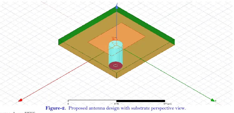
Figure-2. Proposed antenna design with substrate perspective view. Source: Ansys HFSS.
The Figure 2 shows the proposed antenna, in its perspective view, predominantly showing the antenna patch,
From the above design parameters the antenna was modelled and simulated using ANSYS and the following results were obtained.
For an acceptable performance the return loss parameter S11 -15dB . Same goes for the VSWR it is
expected that the VSWR 1.5.
The Return Loss (S11 Parameter) Serves as the Cost, the aim is to adjust the design parameter such that the S11 <= -15dB across the proposed bandwidth of operation, 24.25GHz - 27.5GHz this is one of the primary parameters for grading a good antenna.
Table-1. Dimension parameters of the single antenna element.
Parameters Values Parameters Values
--Antenna dimensions --Feed dimensions
patchX 2.7mm feedX 1mm
patchY 1.2mm feedY 0.1mm
--Shorting pin dimensions coax_inner_radius 0.06mm
shortX -1.2mm coax_inner_radius 0.51mm
shortY -0.3mm feedLength 1.7mm
pin_radius 0.03mm Design frequency 26GHz
--Substrate dimensions gnd_x subX
subH 1.5mm gnd_y subY
subX 6mm
subY 6mm
Source: Ansys HFSS.
The above parameters are the obtained final parameters that resulted in obtaining the stated optimum operating requirements of the antenna element. The optimization was performed using Quasi Newton (Gradient) optimization, in the optimization the return loss S11 set as the cost function with the aim of obtaining a value S11 <= -15dB. This goal was attained and will be discussed.
4. SINGLE ANTENNA ELEMENT ANALYSIS
From the optimization, the results and plots obtained from the optimized parameters antenna are given,
(a) (b)
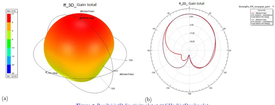
Figure-3. Result (a) 3D directivity plot at 26 GHz (b) 2D polar plot.
Source: Ansys HFSS.
Figure 3a shows the 3D far field plot of the antenna at its centre frequency 26GHz, (b) shows the elevation
(a)
(b)
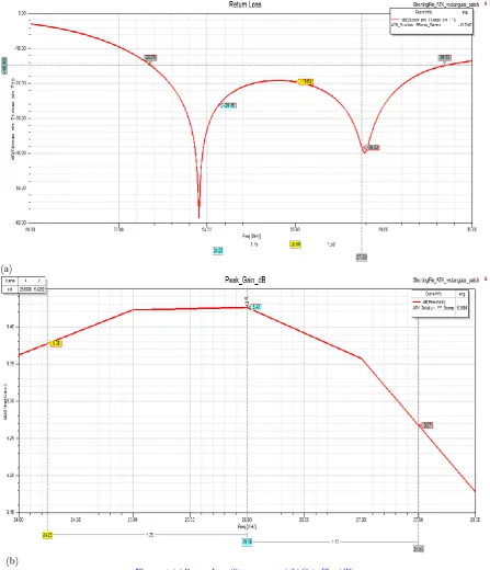
Figure-4. (a) Return Loss (S11 parameter) (b) Gain Plot (dB).
Source: Ansys HFSS.
From the above plots the optimized antenna has performed has good characteristics as intended in its design bandwidth.
Figure 4a shows the return loss plot (S11 parameter) as seen from the diagram, the return loss of the antenna is
impressive over it operating bandwidth a return loss of less than -15dB was obtained, in fact in effect the operating bandwidth of the antenna is 29.38 GHz - 22.73GHz, this gives an impressive bandwidth of 6.6GHz, shows that the antenna is a good choice for 5G wireless network systems.
Figure 4b shows the peak gain of the antenna in its boresight direction, a maximum gain of 5.43dB is attained
Figure-5. VSWR plot.
Source: Ansys HFSS.
Figure 5 shows the VSWR of the antenna, this value aids in evaluating the level of mismatch between the
antenna and its feed network, from the above, a low VSWR of less than 1.5 was obtained. This shows a good match between the antenna and its feed network, which means a low loss value or reflection coefficient as shown earlier in the S11 parameter plot, in Figure 4a.
(a)
(b)
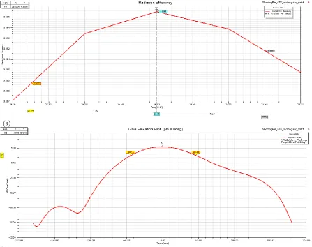
Figure-6(a). Antenna total efficiency (b) Elevation plot of the antenna at phi = 0deg.
Figure 6a shows the plot of the antenna’s efficiency over its operating frequency, it has an average radiating efficiency of 89.2%, peaking out at its centre frequency 26GHz at 89.6%, this is shows high performance, ie the antenna is able to convert 89% of received electrical power at its power into radio waves.
Figure 6b shows the elevation plot of the antenna over the elevation angle theta (H-plane), this shows its half
power (3dB) beamwidth of 50deg.
5. ANTENNA ARRAY DESIGN
In the configuration of this antenna design a 4x4 array is implemented, The 16 element antenna array is of length 41.08 mm × 41.08 mm. A standard low cost FR4 epoxy of a relative dielectric constant 4.4 and loss tangent 0.25 is used as the substrate for printed circuit board of size 41.08 mm × 41.08 mm. The antenna array is spawn from the above single element design a simple rectangular PIFA (planar inverted-F antenna). The antenna is designed to be integrated into the chassis of a mobile device.
The proposed antenna is arranged as a 4x4 element array with a separation of 5.7mm in both the x and y direction between each element to ensure good isolation between the antenna elements and minimize the grating lobes. The antenna array covers a frequency range of 24.25-27.5 GHz with a bandwidth of 3.25 GHz.
The proposed antenna array design is shown in Figure 7.
Figure-7. 16 element 4 x 4 antenna array design.
Source: Ansys HFSS.
Table-2. Dimension parameter for the antenna array.
Parameters Value
--Patch dimensions
Inter patch_spacing (x,y) 5.7mm
Source: Ansys HFSS.
6. ANTENNA ARRAY ANALYSIS
(a)
(b)
(c)
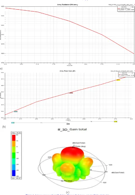
Figure-8. Antenna array results (a) Radiation efficiency (b) Antenna gain (c) 3D directivity plot.
Source: Ansys HFSS.
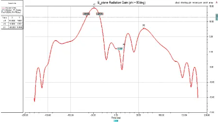
For the beam steering, the alternate excitation phase difference between each column element, is varied with so that the direction of the main beam is being stirred in the E-plane Table 3 below shows the variation of this phase such that the beam is steered at an angle of 48 deg in the E-plane while maintaining an SLL difference value of about of a 6.86dB, the diagram for the radiation pattern at maximum scan angle is shown in Figure 9.
Figure-9. Radiation pattern for maximum scan angle.
Source: Ansys HFSS.
The Table 3 gives the radiation characteristics, this shows information about the radiation when there is no
phase difference ie dhpi = 0deg, and when the amplitude is the same, in this state of excitation, the boresight beam is 0 deg to with respect to the E-plane and a maximum gain of 16.71dB is achieved in this direction and an SLL of 12dB. Also at maximum scan, the phase difference between each element along the column wise elements dhpi = 150deg, this causes the main beam to stir to an angle of about 48 deg along the E-plane, a gain of 14.46dB is achieved and an SLL of 6.86dB. In each state a steady 3dB beamwidth of 30deg was maintained across the scan.
Table-3. E-plane radiation pattern of the antenna array at 26 GHz.
Parameters Beam position Max gain 3dB-beamwidth SLL DHPI
Boresight 0 deg 16.71dB 30 deg 12 dB 0 deg
Maximum scan 48 deg 14.46 dB 30 deg 6.86 dB 150 deg
Source: Ansys HFSS.
In other to have a perspective of the performance of the antenna designed in this work it is compared with other works as shown in Table 4.
Table-4. Comparison with other reported works on millimeter wave antenna array for 5G applications.
Works Imp. bandwidth Gain Rad. efficiency SLL Scan range 3-dB
beamwidth Stanley, et
al. [8] 6 GHz 13 dBi 75% - 120 deg -
Khalily, et
al. [7] 5.37 GHz 19.88 dBi 86% -13.4dB 108 deg 4 deg
7. CONCLUSION
In this work, a novel low cost PIFA antenna has been designed and analysed and is seen to be suitable to deployed in 5G mm-wave mobile devices, due to its compactness, and performance, the antenna performed recommendable over its operating bandwidth of 3.25GHz from 24.25GHz - 27.5GHz, with a low return loss (S11 < -15dB), it also achieved a gain of 5.43dB in its boresight direction. This single antenna element was then scale into a 16 element array of 4x4 configuration, achieving a high gain of 16.71 dB at zero scan angle and a gain of 14.46dB at 48 deg scan angle.
Funding: This study received no specific financial support.
Competing Interests: The authors declare that they have no competing interests.
Contributors/Acknowledgement: Southwest Jiaotong UniversityOur gratitude goes to Engr. Mfonobong
A. Umoren, the Project Coordinator for his enormous contributions in making this project a success.
REFERENCES
[1] C. Sunitha, D. G. Krishnan, and V. A. Dhanya, "Overview of fifth generation networking," International Journal of Computer Trends and Technology, vol. 43, pp. 49-55, 2017. Available at: https://doi.org/10.14445/22312803/ijctt-v43p107.
[2] B. Joe, "5G spectrum bands." Global Mobile Suppliers Association. Available: https://gsacom.com/5g-spectrum-bands, 2017.
[3] C. A. Balanis, Antenna theory: Analysis and design, 3rd ed. New Jersey: John Wiley & Sons, 2005.
[4] W. L. Stutzman and G. A. Thiele, Antenna theory and design, 3rd ed. New Jersey: John Wiley & Sons, 2013.
[5] M. Mantash and T. A. Denidni, "Millimeter-wave beam-steering antenna array for 5G applications," in 2017 IEEE 28th Annual International Symposium on Personal, Indoor, and Mobile Radio Communications (PIMRC), 2017.
[6] A. Khan and R. Nema, "Analysis of five different dielectric substrates on microstrip patch antenna," International Journal of Computer Applications, vol. 55, pp. 40-47, 2012. Available at: https://doi.org/10.5120/8826-2905.
[7] M. Khalily, R. Tafazolli, P. Xiao, and A. A. Kishk, "Broadband mm-wave microstrip array antenna with improved radiation characteristics for different 5G applications," IEEE Transactions on Antennas and Propagation, vol. 66, pp. 4641-4647, 2018. Available at: https://doi.org/10.1109/tap.2018.2845451.
[8] M. Stanley, Y. Huang, T. Loh, Q. Xu, H. Wang, and H. Zhou, "A high gain steerable millimeter-wave antenna array for 5G smartphone applications," in 2017 11th European Conference on Antennas and Propagation (EUCAP), 2017.