Evolution of 4G-Research Directions Towards Fourth
Generation Wireless Communication
B.Vasavi#1,Mounika Marepalli#2, Leepika Gudur#3
Associate Professor#1
, Computer Science and Engineering
Hyderabad Institute of Technology and Management (HITAM) Hyderabad, A P, India
Abstract- Mobile communication play a vital l role in the data
and voice network front. With the deployment of mass scale 3G just around the globe, new directions are already being researched. This paper addresses the fourth generation mobile communication. The Fourth Generation (4G) Mobile Communication not only emphasizes on increase in data rate and new interfaces but it also converse the advanced wireless mobile communication. The high speed wireless access the systems in an Open Wireless Architecture (OWA) platform which has become the hub of this emerging next generation mobile technology. Based on the OWA model, 4G mobile would deliver the best business to the wireless market and Asia-Pacific which happens to be the most dynamic market of new generation mobile communication with over $100 Billion businesses in the next decade. The 4G mobile technology is the intersection and convergence of wireless mobile and wireless access around the globe. Any single architecture wireless system, including 3G, HSDPA, WiMax, etc., is a transitional solution only, and will be replaced by open wireless architecture system very soon where in various different wireless standards can be integrated and converged on open platform. The advent of 4G wireless systems has created many research opportunities. The expectations from 4G are high in terms of data rates, spectral efficiency, mobility and integration.
Keywords - MIMO, GSM, WiMAX, LTE, Pre-coding.
I. INTRODUCTION
The first operational cellular communication system was set up in the Norway in 1981 and was followed by the similar systems in United States and United Kingdom. These first generation systems provided voice transmissions by using frequencies around 900MHz and analog modulation. The second generation (2G) of the wireless mobile network was based on low-band digital data signaling [1]. The most popular 2G wireless technology is known as Global Systems for Mobile Communications (GSM). The first GSM systems used a 25MHz frequency spectrum in the 900MHz band [11]. Initiation for 3G started in the 1980s. Initially it focused on multimedia applications such as videoconferencing for mobile phones. 3G thinking had to evolve as internet user demanded more and more wireless applications and services. As personal wireless handsets become more common than fixed telephones, it is clear that personal wireless Internet access will follow and users will want broadband Internet access. The objective of the 3G was to develop a new protocol and new technologies to further enhance the mobile experience [4]. In contrast, the new 4G framework to be
established will try to accomplish new levels of user experience and multi-service capacity by also integrating all the mobile technologies that exist i.e. GSM - Global System for Mobile Communications, GPRS - General Packet Radio Service, IMT-2000-International Mobile Communications, Wi-Fi-Wireless Fidelity, Bluetooth etc. The main objectives of 4G networks can be stated in the following properties[10] : Ubiquity, Multi-service-platform and low bit-cost.
To achieve the proposed goals, a very flexible network that would combine various radio access technologies must be created. This network must provide high bandwidth, from 50-100 Mbps for high mobility users, 1Gbps for low mobility users and technologies that permit fast handoffs and efficient delivery of service.
Orthogonal Frequency Division Multiplexing (OFDM) is proving to be a possible multiple access technology to be used in 4G. But OFDM comes with its own challenges like high Peak to Average Ratio, linearity concerns and phase noise. This paper proposes a solution to reduce Peak to Average Ratio by clipping method. ATLAB as used to generate the OFDM signal to prove that clipping reduces Peak to Average Ratio.The growth of the number of mobile subscribers over the last years led to a saturation of voice oriented wireless telephony. From a number of 214 million subscribers in 1997 to 1.162 millions in 2002 [1], it is predicted that by 2010 there will be 1700 million subscribers world wide [2]. It is now time to explore novel demands and to find new ways to extend the mobile concept. The first steps have already been taken by the 2.5G, which gave users access to a data network (e.g. Internet access, MMS – Multimedia Message Service). However, users and applications demanded more communication power. As an answer to this demand a new generation with new standards has been developed - 3G. In spite of the big initial euphoria that evolved this technology, only one 3G network exists in commercial use today. This network has been deployed in Japan in 2001 using international standard IMT-2000, with great success.
4G wireless is the term used to describe the fourth-generation of wireless service. 4G is a step up from 3G, which is currently the most prevalent and high-speed wireless service. 4G is only available in limited areas today. Sprint, for example uses WiMax technology for its 4G network, while Verizon Wireless uses a technology called Long Term Evolution (LTE). No matter what technology is behind it, 4G
B. Vasavi et al, / (IJCSIT) International Journal of Computer Science and Information Technologies, Vol. 2 (3) , 2011, 1087-1095
wireless is designed to deliver speed. On an average 4G wireless is supposed to be four to ten times faster than today's 3G networks. Sprint says its 4G WiMax network can offer download speeds that are ten times faster than a 3G connection, with speeds that top out at 10 megabits per second. Verizon's LTE network, meanwhile, can deliver speeds between 5 mbps and 12 mbps.
A. Evolution of 4G
The evolution of mobile service from the 1G (first generation) to 4G(fourth generation) are discussed in this section. This process began with the designs in the 1970s that have become known as1G. The earliest systems were implemented based on analog technology and the basic cellular structure of mobile communication [12]. Many fundamental problems were solved by these early systems. Numerous incompatible analog systems were placed in service around the world during the 1980s.The 2G (second generation) systems designed in the 1980s were still used mainly for voice applications but were based on digital technology, including digital signal processing techniques. These 2G systems provided circuit-switched data communication services at a low speed. The competitive rush to design and implement digital systems led again to a variety of different and incompatible standards [13] such as GSM (global system mobile), mainly in Europe; TDMA (time division multiple access) (IS-54/IS-136) in the U.S.; PDC(personal digital cellular) in Japan; and CDMA (code division multiple access) (IS-95), another U.S. system. These systems operate nationwide or internationally and are today's mainstream systems, although the data rate for users in these system is very limited. During the 1990s, two organizations worked to define the next, or 3G, mobile system, which would eliminate previous incompatibilities and become a truly global system. The 3G system would have higher quality voice channels, as well as broadband data capabilities, up to 2 Mbps. Unfortunately, the two groups could not reconcile their differences, and this decade will see the introduction of two mobile standards for 3G. In addition, China is on the verge of implementing a third 3G system. An interim step is being taken between 2G and 3G, the 2.5G. It is basically an enhancement of the two major 2G technologies to provide increased capacity on the 2G RF (radio frequency) channels and to introduce higher throughput for data service, up to 384 kbps. A very important aspect of 2.5G is that the data channels are optimized for packet data, which introduces access to the Internet from mobile devices[13], whether telephone, PDA (personal digital assistant), or laptop. However, the demand for higher access speed multimedia communication in today's society, which greatly depends on computer communication in digital format, seems unlimited. According to the historical indication of a generation revolution occurring once a decade, the present appears to be the right time to begin the research on a 4G mobile communication system. The Generations of communications is shown in the Table- I .
Table 1: Generations of Communications
II. TECHNOLOGIES OF 4G A. OFDMA
Orthogonal Frequency Division Multiplexing (OFDM) provides clear advantages for physical layer performance and also a framework for improving layers performance by proposing an additional degree of freedom. Using OFDM, it is possible to exploit the time domain, the space domain, the frequency domain and even the code domain to exploit radio channel usage. It ensures very robust transmission in multi-path environments with reduced receiver complexity.
OFDM also provides a frequency diversity gain, improving the physical layer performance[9] .It is also compatible with other enhancement Technologies, such as smart antennas and MIMO.OFDM modulation can also be employed as a multiple access technology (Orthogonal Frequency Division Multiple Access; OFDMA). Here, each OFDM symbol can transmit information to and from several users using a different set of sub carriers (i.e. sub channels)[14]. This provides additional flexibility for resource allocation (increasing the capacity) and also enables cross layer optimization of radio link usage.
B. WiMAX-World Interoperability for Microwave Access :IEEE 802.16 Standard:
The current WiMAX revision is based upon IEEE 802.16e-2005, approved in December 2005. It is a enhancement to the IEEE Std 2004, and so the actual standard is 802.16-2004 as amended by 802.16e-2005[5]. Thus, these specifications need to be considered together.
IEEE 802.16e-2005 improves upon IEEE 802.16-2004 by: Adding support for mobility (soft and hard handover between base stations).
Scaling of the Fast Fourier transform (FFT) to the channel bandwidth in order to keep the carrier spacing constant across different channel bandwidths(i.e. 1.25 MHz, 5 MHz, 10 MHz or 20 MHz).
Advanced antenna diversity schemes, and hybrid
B. Vasavi et al, / (IJCSIT) International Journal of Computer Science and Information Technologies, Vol. 2 (3) , 2011, 1087-1095
automatic repeat-request (HARQ)
Adaptive Antenna Systems (AAS) and MIMO technology
Denser sub-channelization, thereby improving indoor Penetration Introducing Turbo Coding and Low-Density Parity Check (LDPC).
Introducing downlink sub-channelization, allowing administrators to trade coverage for capacity or vice versa.
Adding an extra QoS class for VoIP applications. Application of WiMAX:
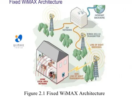
There are two major applications of WiMAX: Fixed WiMAX (IEEE 802.16-2004):
Fixed WiMAX applications are point-to-multipoint enabling the delivery of last mile wireless broadband access as an substitute to cable and DSL for homes and businesses. Fixed WiMAX Adoption is currently available however the adoption rate is impacted by the high cost of equipment in comparison to cable or DSL. It provides greater benefits for developing countries that do not already have physical infrastructure to support wired broadband access as described in the figure 2.1.
Figure 2.1 Fixed WiMAX Architecture Mobile WiMAX(IEEE 802.16-2005) :
Mobile WiMAX offers the full mobility of cellular networks at true broadband speeds. Mobile WiMAX Adoption Mobile WiMAX equipment will arrive to carriers toward the end of 2007. However, mobile equipment testing typically takes between 12 to 18 months before the equipment is introduced to the consumer market as described in the figure 2.2.
Figure 2.2 Mobile WiMAX Architecrure
WiMAX vs. Wi-Fi:
WiMAX vs. Wi-Fi WiMAX / Wi-Fi Comparison: As described in the table II WiMAX and Wi-Fi are somewhat independent, addressing slightly different needs. WiMAX uses private, licensed spectrum and provides Wi-Fi-like service with guaranteed performance to larger public areas, similar in coverage to cellular networks today. Wi-Fi uses shared spectrum and operates at short distances, making it ideal for low-cost, private networks (where usage of the network is constrained to an office building or campus) or free public systems (where service guarantees are not required).
Table II Comparison of WiMAX and Wi-Fi WiMAX Wi-Fi
WiMAX is a long range system, covering many kilometers, that uses licensed/unlicensed spectrum to deliver connection to a network and Internet
Wi-Fi uses unlicensed spectrum to provide access to a local network
WiMAX uses a QoS mechanism based on connections between the base station and user device. Each connection is based on specific scheduling algorithms.
Wi-Fi is more popular in end user devices which operates in short distances
WiMAX network operators provide a WiMAX Subscriber Unit which connects to metropolitan WiMAX network and provides Wi-Fi within the home/ business for local devices
Wi-Fi runs on the Media
Access Control's CSMA/CA protocol, which is connectionless and contention based, whereas WiMAX runs a connection-oriented MAC.
Both 802.11 (Wi-Fi)and 802.16( WiMAX) define Peer-to-Peer (P2P) and ad hoc networks, where in end user communicates to users/ servers on another LAN using its access point/ base station
Wi-Fi uses contention access and all subscriber stations that wish to pass data through a wireless access point (AP) and stations compete for the AP's attention on a random interrupt basis
C. Software Defined Radio
Software Defined Radio (SDR) benefits from today’s high processing power to develop multi-band, multi-standard base stations and terminals. Although in future the terminals will adapt the air interface to the available radio access technology, at present this is done by the infrastructure. Several infrastructure gains are expected from SDR. For example, to increase network capacity at a specific time (e.g. during a sports event), an operator will reconfigure its network adding several modems at a given Base Transceiver Station (BTS). SDR makes this reconfiguration easy and flexible. In the context of 4G systems, SDR will become an
B. Vasavi et al, / (IJCSIT) International Journal of Computer Science and Information Technologies, Vol. 2 (3) , 2011, 1087-1095
enabler for the aggregation of multi-standard pico/micro cells. For a manufacturer, this can be a powerful aid to providing multi-standard, multi-band equipment with reduced development effort and costs through simultaneous multi-channel processing.
D. Multiple Input Multiple Output(MIMO)
MIMO uses signal multiplexing between several transmitting antennas and time or frequency. It is well matched to OFDM, as it is possible to process independent time symbols as soon as the OFDM waveform is correctly designed for the channel. It refers to the technology where there are multiple antennas at the base station and multiple antennas at the mobile device. The usage of multiple antenna technology includes cellular phones with two antennas, laptops with two antennas (i.e. built in the left and right side of the screen), as well as CPE devices with multiple sprouting antennas[2]. This aspect of OFDM significantly simplifies processing. The signal transmitted by m antennas is received by n antennas. Processing of the received signals may deliver several performance improvements: range, quality of received signal and spectrum effectiveness. In principle, MIMO is more efficient when many multiple path signals are received. The performance in cellular deployments is still subject to research and simulations. However, it is generally acknowledged that the gain in spectrum efficiency is directly related to the minimum number of antennas in the link.
MIMO stands for Multiple Input and Multiple Output, The predominant cellular network implementation is to have multiple antennas at the base station and a single antenna on the mobile device. This minimizes the cost of the mobile radio. As the costs for radio frequency (RF) components in mobile devices go down, second antennas in mobile device may become more common. Multiple mobile device antennas are currently used in Wi-Fi technology (e.g. IEEE 802.11n), where WiFi-enabled cellular phones, laptops and other devices often have two or more antennas.
Forms of MIMO: Multi-antenna types
SISO/SIMO/MISO are degenerate cases of MIMO oMultiple-input and single-output (MISO) is a degenerate case when the receiver has a single antenna.
o Single-input and multiple-output (SIMO) is a degenerate case when the transmitter has a single antenna.
o single-input single-output (SISO) is a radio system where neither the transmitter nor receiver have multiple antenna.
Principal single-user MIMO techniques
o Bell Laboratories Layered Space-Time (BLAST), Gerard. J. Foschini (1996)
o Per Antenna Rate Control (PARC), Varanasi, Guess (1998), Chung, Huang, Lozano (2001)
o Selective Per Antenna Rate Control (SPARC), Ericsson (2004)
Functions of MIMO
MIMO can be sub-divided into three main categories, pre-coding, spatial multiplexing or SM, and diversity coding.
- Pre-coding: is multi-stream beam forming, in the narrowest definition. In more general terms, it is considered to be all spatial processing that occurs at the transmitter. In (single-layer) beam forming, the same signal is emitted from each of the transmit antennas with appropriate phase (and sometimes gain) weighting such that the signal power is maximized at the receiver input. The benefits of beam forming are to increase the received signal gain, by making signals emitted from different antennas add up constructively, and to reduce the multipath fading effect. In the absence of scattering, beam forming results in a well defined directional pattern, but in typical cellular conventional beams are not a good analogy. -Spatial multiplexing: requires MIMO antenna configuration. In spatial multiplexing, a high rate signal is split into multiple lower rate streams and each stream is transmitted from a different transmit antenna in the same frequency channel. If these signals arrive at the receiver antenna array with sufficiently different spatial signatures, the receiver can separate these streams into (almost) parallel channels. Spatial multiplexing is a very powerful technique for increasing channel capacity at higher signal-to-noise ratios (SNR). The maximum number of spatial streams is limited by the lesser in the number of antennas at the transmitter or receiver. Spatial multiplexing can be used with or without transmit channel knowledge.
-Diversity Coding: techniques are used when there is no channel knowledge at the transmitter. In diversity methods, a single stream (unlike multiple streams in spatial multiplexing) is transmitted, but the signal is coded using techniques called space-time coding. The signal is emitted from each of the transmit antennas with full or near orthogonal coding. Diversity coding exploits the independent fading in the multiple antenna links to enhance signal diversity. Because there is no channel knowledge, there is no beam forming or array gain from diversity coding.
MIMO Technology in WiMAX
WiMAX implementations that use MIMO technology have become important. The use of MIMO technology improves the reception and allows for a better reach and rate of transmission. The implementation of MIMO also gives WiMAX a significant increase in spectral efficiency.
-MIMO auto-negotiation:The 802.16 defined MIMO configuration[2] is negotiated dynamically between each individual base station and mobile station. The 802.16 specification supports the ability to support a mix of mobile stations with different MIMO capabilities. This helps to maximize the sector throughput by leveraging the different capabilities of a diverse set of vendor mobile stations.
Space Time Code
Figure: 2.3 Space Time Code diagram
B. Vasavi et al, / (IJCSIT) International Journal of Computer Science and Information Technologies, Vol. 2 (3) , 2011, 1087-1095
The 802.16 specification supports the Multiple-input and single-output (MISO) technique of Transmit Diversity, which is commonly referred to Space Time Code (STC). With this method, two or more antennas are employed at the transmitter and one antenna at the receiver as shown in figure 2.3. The use of multiple receive antennas (thus MIMO) can further improve the reception of STC transmitted signals. With a Transmit Diversity rate = 1 (aka "Matrix A" in the 802.16 standard), different data bit constellations are transferred on two different antennas during the same symbol. The conjugate and/or inverse of the same two constellations are transferred again on the same antennas during the next symbol. The data transfer rate with STC remains the same as the baseline case. The received signal is more robust with this method due to the transmission redundancy. This configuration delivers similar performance to the case of two receives antennas and one transmitter antenna.
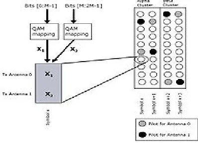
-Spatial Multiplexing: The 802.16 specification also supports the MIMO technique of Spatial Multiplexing (SMX), also known as Transmit Diversity rate = 2 (i.e. "Matrix B" in the 802.16 standard). Instead of transmitting the same bit over two antennas, this method as shown in the figure 2.4 transmits one data bit from the first antenna, and another bit from the second antenna simultaneously, per symbol. As long as the receiver has more than one antenna and the signal is of sufficient quality, the receiver can separate the signals. This method involves added complexity and expense at both the transmitter and receiver. However, with two transmit antennas and two receive antennas, data can be transmitted twice as fast as compared systems using Space Time Codes with only one receive antenna. One specific use of Spatial Multiplexing is to apply it to users who have the best signal quality, so that less time is spent transmitting to them. Users whose signal quality is too low to allow the spatially multiplexed signals to be resolved stay with conventional transmission..
Figure 2.4 Spatial Multiplexing
MIMO Techniques
-Uplink Collaborative MIMO:A related technique is called Uplink Collaborative MIMO, where users transmit at the same time in the same frequency. This type of spatial multiplexing improves the sector throughput without requiring multiple transmit antennas at the mobile device. The common non-MIMO method for this in OFDMA is by scheduling different mobile stations at different points in an OFDMA time-frequency map. Collaborative Spatial
Multiplexing (Collaborative MIMO) as shown in figure 2.5 is comparable to regular spatial multiplexing, where multiple data streams are transmitted from multiple antennas on the same device.
Figure 2.5 Uplink Collaborative MIMO
-WiMAX Uplink Collaborative MIMO: In the case of WiMAX, Uplink Collaborative MIMO is spatial multiplexing with two different devices, each with one antenna (figure 2.5). These transmitting devices are collaborating as shown in the figure 2.6 in the sense that both devices must be synchronized in time and frequency so that the intentional overlapping occurs under controlled circumstances. The two streams of data will then interfere with each other. As long as the signal quality is sufficiently good and the receiver at the base station has at least two antennas, the two data streams can be separated again. This technique is sometimes also termed Virtual Spatial Multiplexing.
Figure 2.6 WiMAX Uplink Collaborative MIMO
Other MIMO-related radio techniques applied to WiMAX
- Adaptive Antenna Steering (AAS), a.k.a. Beamforming :A MIMO-related technique that can be used with WiMAX is called AAS or Beamforming. Multiple antennas and multiple signals are employed, which then shape the beam with the intent of improving transmission to the desired station. The result is reduced interference because the signal going to the desired user is increased and the signal going to other users is reduced.
- Cyclic Delay Diversity: Another MIMO-related technique that can be used in WiMAX systems, but which is outside of the scope of the 802.16 specification, is known as Cyclic Delay Diversity. In this technique, one or more of the signals are delayed before transmission. Because the signals are coming out of two antennas, their receive spectrums differ as each spectrum is characterized by humps and notches due to multi-path fading. At the receiver the signals combine, which
B. Vasavi et al, / (IJCSIT) International Journal of Computer Science and Information Technologies, Vol. 2 (3) , 2011, 1087-1095
improves reception because the joint reception results in shallower spectral humps and fewer spectral notches. The closer the signal can get towards a flat channel at a certain power level, the higher the throughput that can be obtained.
Mathematical description
In MIMO systems, a transmitter sends multiple streams by multiple transmit antennas. The transmit streams go through a matrix channel which consists of all NtNr paths between the Nt transmit antennas at the transmitter and Nr receive antennas at the receiver as depicted in the figure 2.7. Then, the receiver gets the received signal vectors by the multiple receive antennas and decodes the received signal vectors into the original information. A narrowband flat fading MIMO system is modeled as: y =Hx + n. Where and are the receive and transmit vectors, respectively, and and are the channel matrix and the noise vector, respectively.
Figure 2.7 Mathematical representation of MIMO
Referring to information theory, the ergodic channel capacity of MIMO systems where both the transmitter and the receiver have perfect instantaneous channel state information is:
where ()H denotes Hermitian transpose and ρ is the ratio between transmit power and noise power (i.e., transmit SNR). The optimal signal covariance is achieved through singular value decomposition of the channel matrix
and an optimal diagonal power allocation
matrix . The optimal
power allocation is achieved through waterfilling, that is
where are the diagonal elements of
, is zero if its argument is negative, and μ is selected
such that .
If the transmitter has only statistical channel state information, then the ergodic channel capacity will decrease as the signal covariance can only be optimized in terms of the average mutual information as
The spatial correlation of the channel has a strong impact on the ergodic channel capacity with statistical information. If the transmitter has no channel state information it can select the signal covariance to maximize channel capacity under worst-case statistics, which means and accordingly
Depending on the statistical properties of the channel, the
ergodic capacity is mostly times larger than that of a SISO system.
III. The LTE (Long Term Evolution)-High Performance Interface
LTE (Long Term Evolution) is the project name of a new high performance air interface for cellular mobile communication systems. It is the last step toward the 4th generation (4G) of radio technologies designed to increase the capacity and speed of mobile telephone networks. Where the current generation of mobile telecommunication networks are collectively known as 3G, LTE is marketed as 4G.
According to 3GPP, a set of high level requirements was identified
Reduced cost per bit
Increased service provisioning – more services at lower cost with better user experience
Flexibility of use of existing and new frequency bands Simplified architecture, Open interfaces
Allow for reasonable terminal power consumption
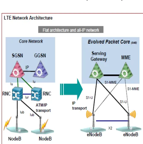
Figure 3.1 LTE Network Architecture
LTE has introduced a number of new technologies when compared to the previous cellular system asdepicted in the figure 3.1. They enable LTE to be able to operate more efficiently with respect to the use of spectrum, and also to provide the much higher data rates that are being required. OFDM (Orthogonal Frequency Division Multiplex) : OFDM technology has been incorporated into LTE because it enables high data bandwidths to be transmitted efficiently while still providing a high degree of resilience to reflections and interference [5].
MIMO (Multiple Input Multiple Output):
One of the main problems that previous telecommunications systems have encountered is that of multiple signals arising from the many reflections that are encountered. By using MIMO, these additional signal paths can be used to advantage and are able to be used to increase the throughput.
SAE (System Architecture Evolution):
B. Vasavi et al, / (IJCSIT) International Journal of Computer Science and Information Technologies, Vol. 2 (3) , 2011, 1087-1095
With the very high data rate and low latency requirements for 3G LTE, it is necessary to evolve the system architecture to enable the improved performance to be achieved. One change is that a number of the functions previously handled by the core network have been transferred out to the periphery. Essentially this provides a much "flatter" form of network architecture. In this way latency times can be reduced and data can be routed more directly to its destination.
A. Requirements for LTE
LTE is focusing on optimum support of Packet Switched (PS) Services. Main requirements for the design of an LTE system were identified in the beginning of the standardization work on LTE [14]. They can be summarized as follows [3]:
- Data Rate: Peak data rates target 100 Mbps (downlink) and 50 Mbps (uplink) for 20 MHz spectrum allocation, assuming 2 receive antennas and 1 transmit antenna at the terminal. - Throughput: Target for downlink average user throughput per MHz is 3-4 times better than release 6. Target for uplink average user throughput per MHz is 2-3 times better than release 6.
- Spectrum Efficiency: Downlink target is 3-4 times better than release
- Latency: The one-way transit time between a packet being available at the IP layer in either the UE or radio access network and the availability of this packet at IP layer in the radio access network/UE shall be less than 5ms. Also C-plane latency shall be reduced, e.g. to allow fast transition times of less than 100 ms from camped state to active state.
-Bandwidth: Scalable bandwidths of 5, 10, 15, 20 MHz shall be supported. Also bandwidths smaller than 5 MHz shall be supported for more flexibility, i.e. 1.4 MHz and 3 MHz. -Interworking: Interworking with existing UTRAN/GERAN systems and non-3GPP systems shall be ensured. Multimode terminals shall support handover to and from UTRAN and GERAN as well as inter-RAT measurements. Interruption time for handover between E-UTRAN and UTRAN/GERAN shall be less than 300 ms for real time services and less than 500 ms for non real time services.
B. LTE Advanced
LTE Advanced (Long-term-evolution Advanced) is a candidate for IMT-Advanced standard, formally submitted by the 3GPP organization to ITU-T in the fall 2009, and expected to be released in 2012. The target of 3GPP LTE Advanced is to reach and surpass the ITU requirements. LTE Advanced is essentially an enhancement to LTE [6]. It is not a new technology but rather an improvement on the existing LTE network. This upgrade path makes it more cost effective for vendors to offer LTE and then upgrade to LTE Advanced which is similar to the upgrade from WCDMA to HSPA. LTE and LTE Advanced will also make use of additional spectrum and multiplexing to allow it to achieve higher data speeds. Coordinated Multi-point Transmission will also allow more system capacity to help handle the enhanced data speeds. Release 10 of LTE is expected to achieve the LTE Advanced speeds. Release 8 currently supports up to 300 Mbit/s download speeds which is still short of the IMT-Advanced standards. The data speed of advanced LTE is 1Gbits for Pea Download and is 500 Mbits for a Peak Upload connection.
C. LTE vs WIMAX
We have noticed that several commenters were confused, critical or just plain wrong about LTE and WiMax, the other 4G network. So few people tried to figure out the salient differences between the two. First, both are 4G technologies designed to move data rather than voice. Both are IP networks based on OFDM technology, rather than rivals and they’re more like siblings. But sibling rivalry does exist, so there are still plenty of differences to hash out. WiMax is based on IEEE standard (802.16), and like that other popular IEEE effort, Wi-Fi, it’s an open standard that was debated by a large community of engineers before getting ratified. The level of openness means WiMax equipment is standard and therefore cheaper to buy sometimes half the cost and is a WiMax network is cheaper to build.
The players of LTE has standardized the technology through 3GPP which comprised of carriers and equipment vendors who have been buying and selling the same proprietary boxes for years. Fred Wright, an SVP that handles 4G networks for Motorola, believes LTE will be the standard chosen by 80 percent of the carriers in the world an it’s a good news for vendors such as such as Alcatel-Lucent and Ericsson, who have opted to stick with LTE. LTE will take time to roll out, with deployments reaching mass adoption by 2012. WiMax is out now, and more networks should be available later this year[5]. As for speeds, LTE will be faster than the current generation of WiMax, but 802.16m that should be ratified in years to come is fairly similar in speeds. So despite their differences in origin and current availability, the two siblings may grow closer with time, especially as newer iterations on the standard emerge. The performance and capabilities of WiMax and LTE will only get better over time, and will represent a direct competitive threat to the existing broadband services. It’s an ambitious goal, and aside from the networking technology, things such as backhaul capacity and availability of network devices will determine how wireless our world will become with the advantages of 4G as depicted in the Table III.
IV. APPLICATIONS OF 4G
Enhanced Mobile Gaming Experience enhanced wireless capabilities that deliver mobile gaming interaction with latency less than five milliseconds. Play online multiplayer games while traveling at high speeds or sitting outside. Personal Media Repository Create a personal media repository that can be accessed from home and on the road to view photos, watch movies and listen to your personal music collection.
Virtual Presence Use hologram-generating virtual reality programs that provide an artificial presence just about anywhere [13]. For example, decide if you want to personally respond when someone rings your front door while you are away from home. Broadband Access in Remote Locations 4G networks will provide a wireless alternative for broadband access to residential and business customers. In addition, 4G will provide the first opportunity for broadband access in remote locations without an infrastructure to support cable or DSL access.
B. Vasavi et al, / (IJCSIT) International Journal of Computer Science and Information Technologies, Vol. 2 (3) , 2011, 1087-1095
Virtual Presence: This means that 4G provides user services at all times, even if the user is off-site.
Virtual Navigation : 4G provides user with virtual navigation through which a user can access a database of the streets, buildings etc.
Tele-Geo processing Applications: This is a combination of GIS (Geographical Information System) and GPS (Global Positioning System) in which a user can get the location by querying[8].
Tele-Medicine and Education: 4G will support remote health monitoring of patients and for people who are interested in lifelong education, 4G provides a good opportunity.
Crisis Management: Natural disasters can cause break down in communication systems. In today’s world it might take days or several weeks to restore the system. But in 4G it is expected to restore such crisis issues in a few hours [7].
Multimedia – Video Services: 4G wireless systems are expected to deliver efficient multimedia services at very high data rates. Basically there are two types of video services: bursting and streaming video services. Streaming is performed when a user requires real-time video services, in which the server delivers data continuously at a playback rate. Bursting is basically file
downloading using a buffer and this is done at the highest data rate taking advantage of the whole available bandwidth.
CONCLUSION
The history of mobile communications shows that several attempts have been made to reduce a number of technologies to a single global standard. Proposed 4G systems offer this promise of a standard that can be embraced worldwide through its key concept of integration. Future wireless networks will need to support diverse IP multimedia applications to allow sharing of resources among multiple users. There must be a low complexity of implementation and an efficient means of compromise between the end users and the wireless infrastructure. The fourth generation promises to accomplish the goal of personal computing and communication with vision of affordably to provide high data rates everywhere over a wireless network. 4G is expected to be launched by mid 2011 and the world is looking forward for the most intelligent technology that would connect the entire world.
REFERENCES
[1] D. Tse and P. Viswanath, Fundamentals of Wireless Communication, Cambridge University Press, 2005.
[2] S. Cui, A. J. Goldsmith, and A. Bahai (August, 2004). "Energy- efficiency of MIMO and Cooperative MIMO in Sensor Networks". IEEE J. Select. Areas of Commun. 22 (6): 1089–1098.
[3] "An Introduction to LTE".3GPP LTE Encyclopedia. http://sites.google.com/site/lteencyclopedia/home.
[4] E. Dahlman, H. Ekström, A. Furuskär, Y. Jading, J. Karlsson, M. Lundevall, and S. Parkvall, "The 3G Long-Term Evolution - Radio Interface Concepts and Performance Evaluation," IEEE Vehicular Technology Conference (VTC) 2006 Spring, Australia, May 20. [5] Kuo-Hui Li, PhD-WiMAX Solutions Division Intel Mobility Group;June 05, 2006.
[6] Kelaskar, M.; Matossian, V.; Mehra, P.; Paul, D.; Parashar, M. (2002), A Study of Discovery Mechanisms for Peer- to-Peer Application, http://portal.acm.org/citation.cfFleishman, Glenn (December 7, 2009).
[7] The future of WiFi: gigabit speeds and beyond". Ars Technica http://arstechnica.com/business/guides.
[8] Garcia Villegas, E.; et al. (2007). "Effect of adjacent-channel interference in IEEE 802.11 WLANs". CrownCom 2007.. ICST & IEEE.
[9] Werner Mohr (2002). "Mobile Communications Beyond 3G in the Global Context" (PDF). Siemens mobile,
http://www.cu.ipv6tf.org/pdf/werner_mohr.pdf.
[10] Mishra, A. R. (2007). In Advanced Cellular Network Planning and Optimisation: 2G/2.5G/3G. Evolution to 4G. The Atrium, Southern Gate, Chichester, West Sussex PO19 8SQ, John Wiley & Sons. [11] Brian Woerner (June 20–22, 2001). "Research Directions for Fourth Generation Wireless" (PDF). Proceedings of the 10th International Workshops on Enabling Technologies: Infrastructure for Collaborative
Enterprises (WET ICE ’01). Massachusetts Institute of Technology, Cambridge, MA, USA.
[12] "4G Coverage and Speeds". Sprint.
http://nextelonline.nextel.com/en/popups/4G_coverage_popup.shtml. [13] "Teliasonera First To Offer 4G Mobile Services". The Wall Street Journal.
[14] http://online.wsj.com/article/BT-CO-20091214-707449.html. 3GPP specification: Requirements for further advancements for E-UTRA (LTE Advanced).
Table: III Comparative Study of 3G Against 4G Requirement :
Architecture
3G(Including
2.5) 4G
Data Elements voice driven. Converged data an d voice over IP
Network Arch Wide area
cell-based Hybrid: Integration of wireless LAN
Speed 384 Kbps to 2 M
bps 20 to 100 Mbps in mobile mode.
Frequency 1800-2400 MHz 2-8 GHz
Bandwidth 5-20 MHz 100 MHz (or more)
Switching Circuit and Pack
et Digitally packetized voice
Access Tech. WCDMA, 1xRT
T OFDM and MC-CDMA
Forward Error Correction
Convolution rate 1/2, 1/3
Concatenated codin g scheme
Component Design
Optimized anten na design, multi-band adapters
Smarter Antennas, Software,multiband and wideband radios
IP A number of air l
ink protocols, IP 5.0
All IP (IPv6)
B. Vasavi et al, / (IJCSIT) International Journal of Computer Science and Information Technologies, Vol. 2 (3) , 2011, 1087-1095
Authors:
1.
Vasavi Bande, is M.Tech in Computer Science from Jawaharlal Nehru Technological University, A.P., India. She has vast experience in Computer Science and Engineering area pertaining to academics and industry related real time projects. She is presently working as Associate Professor in Department of Computer Science and Engineering, Hyderabad Institute of Technology and Management, Hyderabad, A.P, India. She has presented many papers to her credit at National and National conferences. She has presided over as judge to many Paper Presentations and Technical Quizzes. She has authored 3 research papers to date and are published in reputed and indexed International Computer Science Journals. She has guided 20 Students of Master degree in Computer Science and Engineering in their major projects. She is bestowed with the Editorial Member on three International Journals Boards and is nominated as Reviewer to three International Journals. Her area of research include Cloud computing, Network Security, Image Processing, Data Mining, Web Technologies and Emerging Technologies. She can be reached at: [email protected].2. Mounika Marepalli is pursuing B.Tech, Computer Science and Engineering from Hyderabad Institute of Technology and Management, Hyderabad, A.P, India. She has organized Techno-Cultural festivals (esparto) during the year 2010 and 2011. She is life member for STED (Society for Triggering Engineer’s Development, a JNTU Student Chapter) and Sahaya Society (Social Service Organization).She can be reached at [email protected]
3.
Leepika Gudur, pursuing B.Tech,Computer Science and Engineering from Hyderabad Institute of Technology and Management, Hyderabad, A.P, India. She has organized techno and cultural festivals (esparto) during the year 2010 and 2011. She is life member for STED (Society for Triggering Engineer’s Development, a JNTU Student Chapter) and Sahaya Society (Social Service Organization).She can be reached at [email protected]
B. Vasavi et al, / (IJCSIT) International Journal of Computer Science and Information Technologies, Vol. 2 (3) , 2011, 1087-1095