Simulatable Leakage: Analysis, Pitfalls, and new
Constructions
J. Longo Galea1, D. Martin1, E. Oswald1, D. Page1, M. Stam1, and M. Tunstall2
1 Department of Computer Science, University of Bristol,
Merchant Venturers Building, Woodland Road, Bristol, BS8 1UB, United Kingdom.
{jake.longo, dan.martin, elisabeth.oswald, daniel.page, martijn.stam}@bris.ac.uk
2
Cryptography Research Inc. 425 Market Street, 11th Floor San Francisco, CA 94105, United States
Abstract. In 2013, Standaert et al. proposed the notion of simulat-able leakage to connect theoretical leakage resilience with the practice of side channel attacks. Their use of simulators, based on physical devices, to support proofs of leakage resilience allows verification of underlying assumptions: the indistinguishability game, involving real vs. simulated leakage, can be ‘played’ by an evaluator. Using a concrete, block cipher based leakage resilient PRG and high-level simulator definition (based on concatenating two partial leakage traces), they included detailed reason-ing why said simulator (for AES-128) resists state-of-the-art side channel attacks.
In this paper, we demonstrate a distinguisher against their simulator and thereby falsify their hypothesis. Our distinguishing technique, which is evaluated using concrete implementations of the Standaertet al. simu-lator on several platforms, is based on ‘tracking’ consistency (resp. iden-tifying simulator inconsistencies) in leakage traces by means of cross-correlation. In attempt to rescue the approach, we propose several al-ternative simulator definitions based on splitting traces at points of low intrinsic cross-correlation. Unfortunately, these come with signifi-cant caveats, and we conclude that the most natural way of producing simulated leakage is by using the underlying construction ‘as is’ (but with a random key).
Keywords: leakage resilience, side channel attack, simulatable leakage, cross-correlation
1
Introduction
cannot tell the difference between real leakage and simulated leakage (from a simulator that does not know the secret key), then clearly the leakage does not reveal any information about the secret key. This offers a middle ground which connects theorists (who desire provably secure scheme) and practitioners (who require empirically verifiable constructions). In this paper we show that while this is a step in the right direction in terms of modelling leakage, the specific simulator given for their construction is in fact distinguishable. We explain why this is the case, and show how to resolve the problem so that their theoretical proof still holds.
1.1 What is leakage?
A fundamental discrepancy between theory and practice lies in the different un-derstanding of what constitutes ‘leakage’. When examining the vast literature on side channels and leakage resilience, there seem to be three different under-standings of what constitutes a leakage function. The first two of these ideas are typically found in works written by practitioners (such as [8,11]) and centre around a mathematical description of the physical nature of real-world leakage traces. The third, in contrast, seeks to define leakage functions in more general and powerful terms, and is often found in theoretical contributions.
Leakage understood as the modelling of the physical nature of the observed leak-age points. The first understanding is that a leakage function is the mathemat-ical function describing the shape and form of points in leakage traces. Such a function then models the manner in which the operations and data act on the physical environment, alongside other electrical components including the measurement apparatus, and the environment conditions. This understanding of leakage implies that the leakage function fundamentally depends on how the leakage is acquired (because it includes the measurement apparatus). It also implies that the leakage function, whilst being key dependent, is in principle unbounded: every new measurement gives more information.
Leakage understood as modelling of the exploitable information about the key. The second understanding is that of a mathematical function that again de-scribes the leakage traces; however, the conceptual emphasis is that the term ‘leakage’ refers to leakage about the key. A key must have a finite length and therefore the leakage function can never reveal more than that amount of infor-mation. It is hence a function that could (depending on the number of queries to the function), under ideal circumstances, reveal the entire key information but no more than that.
idea is pursued that any ‘realistic’ leakage function is included given the general nature of the definition. The discrepancy that arises from this perspective is that for practitioners, any overhead that is incurred because of ‘proof relics’ or pro-tection against ‘magic’ such as future computation attacks [15] is an unnecessary expense.
1.2 Simulatable leakage
The recent contribution by Standaertet al.[19] hence comes as a welcome ad-dition to the current approaches for dealing with the concept of leakage as part of provable security. In a nutshell, the authors suggest that a sensible notion for leakage resilience is that if real leakage cannot be distinguished from simulated leakage (from a simulator that does not have access to the secret keyk), it cannot contain any information about the key. This approach removes the problem of having to mathematically define a leakage function: instead one gets a concrete instance of it in the form of an actual simulator. Rather than struggling with meaningful definitions for what is leakage, and how to practically derive bounds for it for a concrete device, the new challenge is therefore to define and build (practical) simulators.
The challenge of building concrete leakage simulators for invertible functions was also taken up in [19], where the authors suggest an efficient solution: given some public input xand output c of an invertible schemef, they explain how a trace can be constructed with a random key k∗ that is consistent with the public inputs x and c. This can be done by choosing a random key k∗ and computing c0 =fk∗(x), x0=f−1
k∗(c), and thenc =fk∗(x0) to generate leakage traces L(x) = ll||α, L(x0) = β||lr that can be ‘split up’ (as indicated) and
concatenated to a new simulated trace (ll||lr). The q-sim game, that can be
played in practice, consists of the attacker trying to distinguish real traces from simulated traces givenqreal (or simulated) traces by using whatever state of the art attacks that are available. The rest of [19] consists of two major contributions; first they discuss why state of the art side channel attacks cannot win this game effectively, and, second, they use the game restricted to q= 2 to prove a PRG (using AES as the underlying PRF) construction leakage resilient in the standard model.
1.3 Our contribution
a single key is equivalent to playing a game with one trace forqkeys, this implies we can win the game in an asymptotic setting.
We analyse the properties of (cross-)correlation in this specific application to identify the factors that impact on the ability to win the game efficiently. The factors are the (intrinsic) cross-correlation between points in leakage traces, and the ratio between signal and noise. Whilst changing the ratio between signal and noise is well understood and practically achievable, it is not sufficient with re-gards to decreasing an adversary’s chance to win theq-simgame. Our attempts to work with points that have low intrinsic cross-correlation were only success-ful in theory: for the concrete instantiations in our paper, which are based on AES, there (in theory) should exist such points because of the nature of Sub-Bytes. Theoretically, the input and output of the SubBytes operation are highly uncorrelated. However, we explain why in practice it remains a challenge to exploit this. Finally we suggest a method that indeed withstands the powerful cross-correlation distinguisher, which is based on instantiating the PRG with a double block cipher construction. Our proposed simulator then uses a meet-in-the-middle technique to determine keys that map x to c without introducing inconsistencies in the data flow. This simulator is somewhat theoretical because of the implied computation cost. However it allows the proof given in [19] to hold once more (remember that this proof crucially depends on the existence of a simulator).
Finally we note in our work that even the computationally expensive simu-lator still requires noisy traces: it would seem then that the most natural way to produce simulated leakage is to just use the construction ‘as is’ and run it with a random key. For sufficiently noisy traces even profiling prior to the game will not help an attacker: noisy leakage implies that an adversary must have suffi-ciently many traces to distinguish real from simulated leakage. By limitingqin the game stage this will be infeasible. With this somewhat simple fact in mind, we can argue that leakage can be simulated for any cryptographic primitive or construction. It however requires implementations with high noise.
2
Simulatable leakage: Standaert
et al.
’s model
Before we discuss the model introduced by Standaert et al. in [19], we will introduce the required notation. The probabilistic leakage of a block cipher will be given as BCk(x) l
def
= L(k, x) where L is the leakage function, x is the plaintext andkthe secret key. The leakage function can be described as a vector
l= (l1, l2, ...). For a block cipher, which typically consists of several encryption rounds, we group those trace points corresponding to a round and indicate this by placing the round number as a superscriptli. For AES-128 we can represent a
leakage asl= [l1, . . . , l10].We will later require to split and concatenate leakage vectors. For this purpose we use the short-handli,j= [li, . . . , lj] to denote that
we take the parts of the leakage vector that correspond to rounds i up to j. To highlight where we ‘split and concatenate’ within leakage vectors we use ||
and so denote such a set with bold typesetting, i.e. lnow is a set of leakages, li,j= [li, . . . ,lj] now means that we refer to roundsiuntiljin all leakages in the
set. Finally, if we need to differentiate between points within multiple leakages we will use a subscript, i.e.,lu= (l1,u, l2,u, ...) means we index theu-th point in
each leakage vector inl. Now that the notation has been defined, we are ready to discuss the model.
2.1 Model and q-sim Game
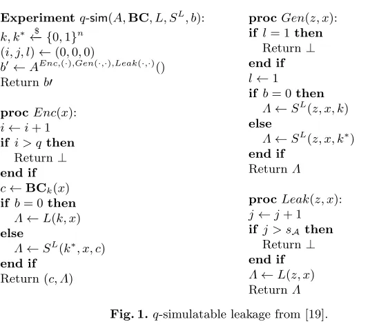
Figure 1 describes the q-simulatable leakage game (q-sim) from [19] for com-pleteness. Recall that the intuition captured in the q-sim game is that if an adversary cannot distinguish real (i.e. depending on the secret key) from sim-ulated (i.e. depending on a random key) traces, the real traces cannot contain any information about the secret key. In the game, the adversary can make q
queries to the Enc oracle and receives back the encryption of x under key k
and either the real leakage L(k, x) or the simulated leakage SL(k∗, x, c). The adversary can also makesAqueries to the leakage oracle with a chosen key and message, which represents profiling a device (i.e. the adversary can attempt to derive (compute, or represent) the otherwise unknown leakage function). We note that this, in particular, allows an adversary to query the leakage function on the inputs from the game, so templates specifically for the inputs used in the game can be derived. The last oracle which can be called once isGenwhich delivers simulated leakage for a chosen message/key pair where either the real or random key in the game is output as the ciphertext. This is to represent the fact that often encryption keys themselves are the result of block cipher invoca-tion, i.e. in practice (and in the constructions discussed in [19]) the encryption key used in roundris generated as the output of the block cipher in the previ-ous roundr−1. The adversary’s advantage is calculated asAdvqL,S-simL,BC(A) =
|Pr[q-sim(A,BC, L, SL,1) = 1]−Pr[q-sim(A,BC, L, SL,0) = 1]|.
2.2 Construction
The model given in [19] is used to prove the security of a leakage-resilient PRG which is instantiated using block ciphers (we will continue the pattern started in [19] and will instantiate the block cipher with AES). This construction show on the left in Fig. 2 and the underlying 2PRGis shown on the right in Fig. 2. When considering this within theq-simgame we note that each key is only used twice (once to create the PRG output and one to create the new key) and thus the value of q= 2 is the one of interest.
2.3 Simulator
Experimentq-sim(A,BC, L, SL, b):
k, k∗←− {0$ ,1}n (i, j, l)←(0,0,0)
b0←AEnc,(·),Gen(·,·),Leak(·,·)() Returnb0
procEnc(x):
i←i+ 1 if i > q then
Return⊥ end if
c←BCk(x) if b= 0then
Λ←L(k, x) else
Λ←SL(k∗
, x, c) end if
Return (c, Λ)
procGen(z, x): if l= 1then
Return ⊥ end if
l←1 if b= 0then
Λ←SL(z, x, k) else
Λ←SL(z, x, k∗) end if
ReturnΛ
procLeak(z, x):
j←j+ 1 if j > sAthen
Return ⊥ end if
Λ←L(z, x) ReturnΛ
Fig. 1.q-simulatable leakage from [19].
k0
2PR
G k1
c1 2PR
G k2
c2 2PR
G k3
c3 2PR
G k4
c4 BC BC p0 p1 k3 k4 c4 2PRG
Fig. 2.Left: Leakage resilient PRG. Right:2PRGconstruction.
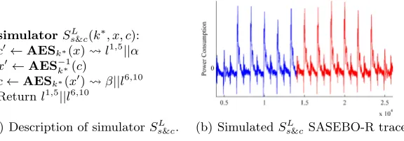
k∗ and records the leakage. The next step is to decryptcunderk∗ to get a new plaintextx0. The final stage is to encryptx0underk∗(note that this will encrypt
toc) and record the leakage. The leakage is the split (in half) and concatenated such that the first part of the new trace corresponds to the leakage on xwhile the second half corresponds to the leakage on c. This simulator is referred to as split and concatenate (Ss&c) simulator and we will refer to traces from this
simulator as s&c-traces.
3
The Security Game for the Practical Use of the
2PRG
:
the
p
-
q
-sim
Game
simulatorSs&cL (k
∗
, x, c):
c0←AESk∗(x) l1,5||α
x0←AES−k∗1(c)
c←AESk∗(x0) β||l6,10 Returnl1,5||l6,10
(a) Description of simulatorSL
s&c. (b) SimulatedSs&cL SASEBO-R trace.
Fig. 3.Definition for theSLs&c simulator and an exemplary trace.
pdifferent keys) and then he must work out if the leakage he is seeing real or simulated leakage for all of thepinstantiations.
We argue further that the p-q-sim game is in general more appropriate: in an evaluation context, which is what [19] really consider, theq-simgame would be played for real, and it seems unlikely that an evaluator would only ever play the game once and takeqtraces (especially ifqis small). More likely, one would play this game several times to get a sense of the success rate forqtraces.
It would be tempting to believe that an adversary cannot exploit the infor-mation leakage across different games because they are based on different keys. Traditional side channel distinguishers require after all to make key-dependent hypotheses: hence whenever a new key is introduced the attacker is presented with a new, fresh challenge. Whilst [19] discusses why the original q-sim game does not hybridise with respect to q, they do not consider the possibility that the game does hybridise in the number of keysp. If the game were to hybridise, then we would have that AdvpL,S-q-simL,BC(A)≤p·Adv
q-sim
L,SL,BC(A); the game gets
easier to win if it is played more often.
In the next section we will show a distinguisher that can work across different keys and thus can take advantage of the full (and more realistic)p-q-simgame.
4
Breaking the split-and-concatenate simulator
Whilst the proposed simulator can be instantiated with any invertible function, we continue to follow Standaert et al.’s exposition and use implementations of AES-128 as running examples. To explain why cross-correlation is an efficient distinguisher we briefly recall how a typical side channel trace relates to the information flow in an AES implementation.
4.1 Properties of real world leakage
(a) Power trace showing a single AES round.
(b) Power trace showing individual as-sembly instructions.
Fig. 4.Power traces for an 8051 8-bit microcontroller.
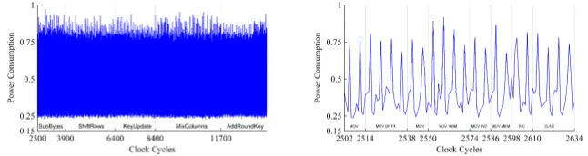
and updated according to the AES round function. As all high level functions (SubBytes, MixColumns, etc.) are processed by some gates at the lowest level, a clock signal is involved that governs (to some extent) when data flows be-tween gates. All changes in gates, in each clock cycle, produce some form of leakage (time for signals to travel, power consumed, radiation emitted) that becomes available through observing the device. Figure 4 illustrates the power consumption measurements from an AES implementation on a simple 8-bit mi-crocontroller (i.e. all intermediate values are represented as bytes). Evidently, we can see patterns in Fig. 4(a), which represents a single AES round.
In case of this very simple processor, we can even identify the effect (with regard to shape and height) of individual instructions in the power consumption by zooming into the trace further, see Fig. 4(b). It shows now only a small part of the first round that corresponds to performing the SubBytes operation. The instructions used for this purpose are register transfers, (MOVand MOVC), a register increment (INC), and conditional branches which correspond to a loop that runs through the 16 state bytes.
In a parallel implementation, each operation will touch multiple state bytes but the sequence of round functions must remain sequential. SubBytes is some-times implemented using combinational logic in dedicated hardware [22]. A com-binatorial logic circuit is not governed by a clock but the output from such a circuit will typically be connected to a synchronous storage element. Referring to Fig. 5(c) we can see that there are 10 visible peaks relating to the AES-128 rounds.
4.2 Cross-correlation as a distinguisher
Cross-correlation is a term coined in signal processing and is commonly used to identify (and measure) similarities of wave forms. It has been used in the context of side channel analysis before, e.g. [13,18,21].
We make the simple observation that the cross-correlation of signals of length one (i.e. points) equates to computing the correlation between trace points (lu,lv) (as opposed to the correlation with key-dependent predictions in the
DPA context). Equation (1) recalls how (Pearson) correlation is defined and estimated.
ρ(lu,lv) =
Cov(lu,lv) p
V ar(lu)·V ar(lv)
(1)
=
P
i(li,u−l¯u)·(li,v−l¯v) q
P
i(li,u−l¯u)2·Pi(li,v−l¯v)2
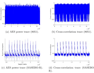
Cross-correlation traces We recall that cryptographic algorithms are imple-mented as step-wise processes (with varying degrees of parallelism). Although AES mixes keying material and input efficiently, and so the correlation between key, input, and output is small, we can expect a high correlation between the subsequent states, e.g. we expect a high correlation between the input and out-put of ShiftRows, as well as states that operate on the same data (even though they might be separated in time). This in turn implies that we can expect a high correlation between subsequent points within leakage traces (see [11, Ch. 4]), as well as points that are related to the same intermediate values. Further to that we can also expect high correlations between data that is related to the program state but independent of the states, e.g. the value of the program counter, point-ers to memory locations, etc. Hence any implementation will lead to a specific cross-correlation trace depending on the data flow.
By producing a cross-correlation trace that shows the cross-correlation ofall pairs of points, i.e.{ρ(lu,lv),∀(u, v)}, we can consequently track the consistency
of data flow. Such a trace however would be very long (the length would be the square of the original traces’ length). We hence opted to reduce the cross-correlation data by selecting the highest cross-cross-correlation value for each uover all ‘distant’ pairs (lu,lv), i.e. for each uwe took ρeu =max{ρ(lu,lv)∀v} where v is not within a small window around u. Hence our cross-correlation traces
e
ρ={ρeu,∀u} have the same length as the actual leakage traces, and they have
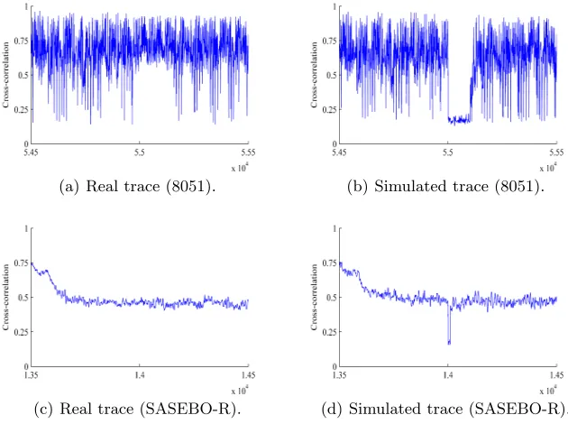
uninformative trivial cross-correlation removed because neighbouring points are not considered. Consequently the cross-correlation traces show the effect of data consistency, and any ‘dip’ implies some form of discontinuity in the data flow.
(a) AES power trace (8051). (b) Cross-correlation trace (8051).
(c) AES power trace (SASEBO-R). (d) Cross-correlation trace (SASEBO-R).
Fig. 5.AES power traces and cross-correlation plots.
second device features a highly parallel implementation of AES. Such an imple-mentation is more likely to be found in high end products where impleimple-mentation speed and security is considered an important factor.
4.3 Detecting s&c-traces
In the proof given in [19], an adversary plays theq-sim game and so has access to the oraclesEnc, Leak, and Gen(an adversary may also query them in the
p-q-simgame). Our distinguisher does not require any access to the oraclesLeak
andGen.
To detect thes&c-traces we apply the cross-correlation method to a set ofq
leakage traces. The detection is then based on the absence of cross-correlation that would otherwise be present in traces that have not been simulated, i.e. a set of points which leak on the same data no longer show a significant correlation with respect to each other.
a cross-correlation trace from the simulated leakages will show such patterns, see right hand side of Fig. 5. Only at the round where the simulated traces have been split and concatenated a different pattern will occur. Consequently an attacker gets a ‘fingerprint’ for how the cross-correlation trace should look (in the case of the s&c-simulator) by examining the beginning and end of the cross-correlation trace. Any significant deviation from the fingerprint (i.e. any discrepancy between the two) will hence identify the s&c-traces.
4.4 Experiments for real devices
Practical attacks are often played down because they are device specific and hence it is often not possible to draw general conclusions from a single attack. However, the heart of the proposal in [19] is to be able to implement a secure simulator on some real world devices. We consequently did not want to resort to ‘pure simulations’ and opted to fully implement simulators for several real world devices. By choosing different devices we can refute the argument that our analysis outcomes are not valid in general: the devices we choose have differ-ent architectures that lead to differdiffer-ent AES implemdiffer-entations, differdiffer-ent leakage models and different noise characteristics.
AES can be implemented in different ways. Serial implementations are often found on small processors (8-bit or 32-bit). These are software-only implemen-tations and we have used two different widely-used processors to instantiate such a software implementation for our attacks. Parallel implementations can be found as dedicated hardware implementations. In practice 32-bit implementa-tions would be considered as suitable for constrained devices such as smart cards, whereas highly parallel 128-bit architectures would be used when throughput is a practical concern. We opted to use a highly parallel 128-bit architecture to provide contrasting results to the software implementations. In the following, we give a brief overview of the results obtained from each architecture. Details regarding the acquisition setup and target devices can be found in Appendix A.
Software implementations We used a general purpose microcontroller which features an 8051 instruction set as the first device for our attacks. The cross-correlation plots for this architecture reveal detailed information about the data flow during the execution of an algorithm. In our running example (AES-128), we are able to detect the order in which state bytes and functions are accessed, the operations performed and for a masked implementation, when and where each masked is applied. In Fig. 6(a) and 6(b) we show a portion of the cross-correlation for real and simulated leakage traces respectively. There is a clear break in the cross-correlation as a result of the concatenation between traces with inconsistent states. We repeated thes&cexperiment with an ARM1based 32-bit architecture and implementation. Like for the 8051, we can track the AES data flow and so the simulated leakage trace, once again, leads to a drop in the cross-correlation.
1
(a) Real trace (8051). (b) Simulated trace (8051).
(c) Real trace (SASEBO-R). (d) Simulated trace (SASEBO-R).
Fig. 6.Cross-correlation distinguisher plots.
Hardware implementation The SASEBO-R ASIC boasts a large number of cryptographic functions implemented as dedicated logic. Unlike the two previ-ous devices, the information leaked is no longer dependant on processor oper-ations but on combinatorial switching. Figures 5(c) and 3(b) show the power consumption over an execution of AES and a simulated trace generated by the
s&csimulator respectively. The cross-correlation distinguisher now plays on the coherency of the combinatorial switching rather than the state leakage at each clock cycle. As with the software implementations, we can easily identify the simulated leakage traces, see Figs. 6(c) and 6(d). One key difference over the software implementation is cross-correlation no longer reveals any information about the data flow or what operations are being performed but simply that there exists some data dependency in the power consumption of the device.
4.5 Measures to secure the split-and-concatenate simulator
Recall that we estimate the cross-correlation between trace points, which implies varying inputs and/or keys. The number of different inputs per key isq, whereas the number of different keys isp. We may hence decide to increasepand keep
We now discuss how traditional engineering-style countermeasures impact on the success of winning the game. We begin by showing how noise on leakage traces will help to make winning the game harder. We then explain why masking and hiding approaches are unlikely to defeat the cross-correlation distinguisher.
Increasing the noise Just as we can write down a formula for the impact of the signal-to-noise ratio (SNR) on a correlation-based DPA attack (see, e.g. [10, Ch. 4.3.1]), we can express the impact of the SNR on our proposed cross-correlation attack.
For this we write leakage points as a direct sum of an (unknown) signal (S) plus independent (Gaussian) noise (N), i.e.lu=Su+Nu, withNu∼ N(0, σu),
and lv =Sv+Nv, withNv ∼ N(0, σv) [3,11]. The signal to noise ratio (SNR)
is defined as SN R = V arV ar((NS)). The respective SNRs at the points u and v are thenSN Ru=V ar(Su)/V ar(Nu) andSN Rv =V ar(Sv)/V ar(Nv). Making the
simplifying assumption that SN Ru ≈SN Rv = SN R, it turns out (using the
same technique as [10, Ch. 4.3.1]) that
ρ(lu,lv) =ρ(Su,Sv)·
1 1 +SN R1
In comparison to a DPA attack (we refer to [10, Ch. 6.3]), the impact of the SNR is potentially stronger on this distinguisher. However, because this distinguisher hybridises over different keys, it is also easier to gather more leakage traces to compensate for this. In particular, it follows that asymptotically over an increasing number of keyspwe can still win the game for any smallq.
More complex/parallel architectures Another important observation at this point is that in contrast to DPA attacks, the ‘relative size’ of the intermediate value (in terms of its bit length in contrast to the overall device state) itself is less important. At first glance this goes against the intuition from DPA style attacks where practice has shown that they become harder for architectures that employ a larger data-path (and so the intermediate values that are attacked contribute only a small amount to the overall leakage). For instance, DPA style attacks on 32-bit processors often only predict 8 bits of the 32-bit state, so the remaining 24 bits are noise. In addition, in DPA style attacks using correlation one requires to ‘model’ the leakage behaviour, and especially for dedicated hardware, standard models such as the Hamming weight or Hamming distance are less than ideal approximations.
Masking and hiding approaches It would be tempting to assume that any countermeasure against correlation-based DPA attacks would automati-cally work against the cross-correlation distinguisher because both distinguishers share the same statistical method.
The two main engineering approaches to distinguish classes of countermea-sures are hiding and masking [11]. Hiding countermeacountermea-sures typically change the SNR and so increase the number of leakage traces that are needed for a successful attack.
Masking (i.e. secret sharing) countermeasures aim to make exploiting the information impossible by distributing it over different intermediate values (and hence leakage points), such that it becomes increasingly infeasible to ‘recom-bine’ that information. In practice however it is not possible to implement secret sharing with many shares. Typically only two, or at most three, shares are used and the masks (i.e. randomness) are not refreshed in between rounds or in be-tween invocations of an intermediate value [7,6]. Consequently, practical mask-ing schemes maintain the consistency between the subsequent transformations on the state and so the cross-correlation distinguisher remains applicable.
5
The challenge of making secure simulators
Given that traditional countermeasures are not suitable to rescue the split-and-concatenate simulator, we have to come up with new ideas. Two approaches are (intuitively) worth pursuing. Firstly, this is to try and maintain state consistency across the concatenated traces. Secondly, this is to split where there is a ‘natural’ discontinuity in the data flow.
5.1 Maintaining state consistency
Over the execution of any algorithm there exists a degree of consistency be-tween the intermediate values, which is disrupted by splitting traces. Hence, we attempted to design a ‘state aware’ simulator by generating an ‘intermediate round’ that ensures such consistency.
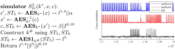
This simulator shown in Fig. 7 and the extra notation can be understood as follows;STiis the state of AES at the start of theithround andAES1k runs a
single round of AES on round key k.
The simulatorS2c operates similarly to Ss&c by first performing an
encryp-tion of xunder the key k∗. The leakage captured from this corresponds to the
first four rounds l1,4. We also store the state ST
5. Next, the encryption of x0 under k∗ is performed and the leakage of the last 5 rounds is captured l6,10 along with ST6. To connect the two otherwise disconnected states we generate an extra trace AES1k#(ST5) l5. Note that finding the key k# which maps
ST5 toST6is simple considering only a single round of AES.
We proceeded to implement theS2c simulator for the 8051 and the resulting
simulatorS2cL(k∗, x, c):
c0, ST5←AESk∗(x) l1,4||α
x0←AES−k∗1(c)
c, ST6←AESk∗(x0) β||l6,10 Constructk#usingST5, ST6
ST6←AES1k#(ST5) l5 Returnl1,4||l5||l6,10
Fig. 7.Simulator description and cross-correlation comparison forS2c.
is to achieve state consistency because we have to take into account the AES state as well as the AES key schedule (in the p-q-sim game), and the fact that different instructions can leak subtly differently.
5.2 Leveraging an algorithm-dependent data-flow discontinuity.
Given our running example is AES, the natural candidate intermediate value is SubBytes, because the input and output of SubBytes are (almost) statistically uncorrelated. We can hence expect that there is also only a low correlation be-tween the corresponding trace points, which implies that the data flow across SubBytes is somewhat discontinued. We tested this idea first on an 8051 soft-ware emulator which produces noise-free leakage on the data processed at each instruction. The simulated traces were indeed indistinguishable from real traces (taken from the emulator) produced. Consequently we attempted to implement this on real devices.
On real devices, one has two implementation choices for SubBytes. Either a table is stored and hence a SubBytes computation corresponds to a table lookup operation. This is suitable for somewhat ‘serial’ implementations, as typically only a single instance of the table is held in logic. This is the option used in our AES software implementations. Alternatively, one implements it as combi-national circuit, which is hence suitable for dedicated hardware platforms. This option is used in the hardware AES on the SASEBO-R.
Our new simulatorSsbc ‘tweaks’ theSsL&c simulator construction to perform
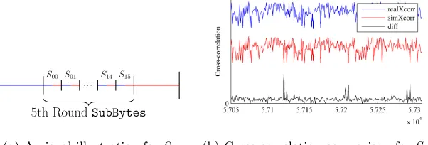
the split-and-concatenate at the S-box lookup rather than points of ‘no activ-ity’. However, we note that for a sequential lookup, the simulator is required to perform splice at each S-box rather than a simple split-and-concatenate as illustrated by Fig. 8(a) (hence we effectively ‘chop up’ a trace).
S00 S01 S14 S15
5th RoundSubBytes
(a) A visual illustration forSsbc. (b) Cross-correlation comparison forSsbc.
Fig. 8. Illustration for a serial Ssbc simulator and a cross-correlation comparison of
Ssbcfor the 8051 microcontroller.
leaks multiple times for each operand. To be precise: consider the lookup r0=
M[A], where a registerr0is loaded with the contents of memory addressA. The resulting leakage trace resembles the form [L(A)||L(M[A])||L(A)||L(M[A])] for some leakage functionLin our 8051 processor.
As a result, the simulator for the 8051 needs to splice multiple times within each S-box lookup. This behaviour is clearly very architecture specific. Fig-ure 8(b) shows the cross-correlation resulting from splicing at each S-box; the top plot (printed in blue) shows the cross-correlation trace as derived from real traces. The middle plot (printed in red) shows the cross-correlation trace as derived from simulated (Ssbc) traces. Whilst a visual detection seems difficult
at first, an adversary with information about the time points (or a fingerprint, which we explained previously can be constructed even from simulated traces) can spot the difference. This is made clear by the lowest plot (printed in black) that shows that there is a distinct difference between real and simulated cross-correlation.
A practical attempt for the SASEBO-R. We now consider the implications of a parallel combinatorial SubBytes function as performed by the SASEBO-R ASIC. Pinpointing the SubBytes operation is no longer such a trivial task as each round function is evaluated as a combinatorial circuit rather than being governed by an external clock. Attempting to model the leakage in an ideal setting would also require significant knowledge of both the design and layout of the ASIC. We hence resorted to a exhaustive search over a whole encryption round in order to determine whether or not a point existed that would allow us to build theSsbcsimulator for such a device.
simulatorSL(x, c):
Perform a meet–in–the–middle attack to learn a valid (k∗i, k∗ 0 i ) BCk∗
i(BCk∗0
i
(x)) Λ
ReturnΛ
Fig. 9.A generic simulatorS secure against the cross-correlation distinguisher.
6
A sound simulator
The previous section has shown that the intuitions for building secure simulators failed to translate to the practical devices that we considered. Furthermore, how they failed leaves us with little confidence that using other platforms, e.g. embedded platforms (with other processors) or a different combinational circuit for SubBytes, would be any more successful. The fundamental hurdle is simply that real world leakage is complex, and cryptographic algorithms are necessarily implemented via step-wise processes. Hence there is a specific data flow that will be somehow disrupted when using a split-and-concatenate approach. Without substantial alterations to the devices’ designs this cannot be easily changed.
Splitting within one instantiation of a block cipher seems hence futile: but how about considering constructions that are based on two somewhat indepen-dent block cipher calls?
6.1 Doubling the cipher
Now we discuss an approach based on using a double block cipher (i.e. a block cipher2BC that consists of two sequential computations of a block cipherBC with independent keys ki and k0i): c = BCki(BCk0
i(x)). In this construction
there is a natural discontinuity between the first and the second encryption with regards to the key state and so the data flow across the ‘boundary’ between the first and the second encryption. This makes this boundary an ideal place to ‘split’ traces, and a generic simulatorS that uses a meet–in–the–middle technique [9] to find a suitable pair of keys follows immediately (see Fig. 9).
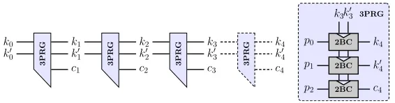
For completeness we show that this simulator can be plugged into the PRG construction from [19] maintaining the correctness of the proof. We only switch out the underlying PRF from AES to double AES, and subsequently we need to switch the2PRGfor a3PRGfor the extra rekeying material. The proof given in [19] can be expanded for any constant number of calls to the PRF and thus the construction will not need to be reproved secure. The resulting construction can be seen in Fig. 10.
6.2 Some final considerations
k0
3PR
G
k00
k1
k10
c1 3PR
G k2
k20
c2 3PR
G k3
k30
c3 3PR
G k4
k40
c4 2BC 2BC 2BC p0 p1 p2
k3k30
k4
k0 4
c4
3PRG
Fig. 10.The adjusted PRG construction.
cross-correlation distinguisher per design so a practical implementation is not necessary in that regard.
However, its security against standard DPA attacks still needs to be con-sidered. Recall that this already is an advantage because DPA attacks do not hybridise over different keys!
Considering now a standard DPA on SL one would notice (in the process
of performing such an attack) that no key hypothesis ever achieves a good cor-relation with the simulated traces. Hence for a DPA distinguisher we need to consider the question of how many traces are necessary to decide with some certainty that all key candidates are equally likely. We leave this as an option question but note that the usual arguments for DPA success (or lack thereof) will apply. These are that for a (reasonably) low SNR, and a small number of leakage traces q, an attack does not succeed. In particular for the purposes of the PRG construction from [19], which limitsqto be two, practical instantiation ofS on an ASIC such as the SASEBO-R should be feasible.
Acknowledgements. Daniel Martin and Elisabeth Oswald have been supported in part by EPSRC via grant EP/I005226/1, and Daniel Page by EP/H001689. Jake Longo Galea has been supported in part by a studentship under the EPSRC Doctoral Training Partnership (DTP) scheme.
References
1. Atmel. AT89S8253 Datasheet. http://www.atmel.com/Images/doc3286.pdf. 2. E. Brier, C. Clavier, and F. Olivier. Correlation power analysis with a leakage
model. InCHES, pages 135–152. LNCS 3156, 2004.
3. S. Chari, C.S. Jutla, J.R. Rao, and P. Rohatgi. Towards sound approaches to counteract power-analysis attacks. InCRYPTO, pages 398–412. LNCS 1666, 1999. 4. S. Dziembowski and K. Pietrzak. Leakage-resilient cryptography. InFOCS, pages
293–302, 2008.
5. S. Faust, T. Rabin, L. Reyzin, E. Tromer, and V. Vaikuntanathan. Protecting circuits from leakage: the computationally-bounded and noisy cases. In EURO-CRYPT, pages 135–156. LNCS 6110, 2010.
6. G. Fumaroli, A. Martinelli, E. Prouff, and M. Rivain. Affine masking against higher-order side channel analysis. InSAC, pages 262–280. LNCS 6544, 2010. 7. C. Herbst, E. Oswald, and S. Mangard. An AES smart card implementation
8. P.C. Kocher, J. Jaffe, and B. Jun. Differential power analysis. InCRYPTO, pages 388–397. LNCS 1666, 1999.
9. X. Lai and J.L. Massey. Hash function based on block ciphers. InEUROCRYPT, pages 55–70. LNCS 658, 1992.
10. J. Longo Galea, D. Martin, E. Oswald, D. Page, M. Stam, M. Tunstall. Simulatable leakage: analysis, pitfalls, and new construction. Cryptology ePrint Archive, Report 2014/357 https://eprint.iacr.org/2014/357.
11. S. Mangard, E. Oswald, and T. Popp. Power Analysis Attacks: Revealing the Secrets of Smart Cards. Springer, 2008.
12. S. Mangard, E. Oswald, and F.-X. Standaert. One for all - all for one: unifying standard differential power analysis attacks. IET Information Security, 5(2):100– 110, 2011.
13. T.S. Messerges, E. Dabbish, and R.H. Sloan. Power analysis attacks of modular exponentiation in smartcards. InCHES, pages 144–157. LNCS 1717, 1999. 14. NXP. LPC2124 Datasheet. http://www.keil.com/dd/docs/datashts/philips/
lpc2114_2124.pdf.
15. K. Pietrzak. A leakage-resilient mode of operation. InEUROCRYPT, pages 462– 482. LNCS 5479, 2009.
16. SASEBO. SASEBO Crypto LSI Specification. http://www.rcis.aist.go.jp/ files/special/SASEBO/CryptoLSI-ja/CryptoLSI2_Spec_Ver1.0_English.pdf. 17. SASEBO. SASEBO-R Specification. http://www.rcis.aist.go.jp/files/
special/SASEBO/SASEBO-R-ja/SASEBO-R_Spec_Ver1.0_English.pdf.
18. L. Sauvage, S. Guilley, F. Flament, J.-L. Danger, and Y. Mathieu. Blind cartog-raphy for side channel attacks: Cross-correlation cartogcartog-raphy. Int. J. Reconfig. Comp., 2012(15):1–9, 2012.
19. F.-X. Standaert, O. Pereira, and Y. Yu. Leakage-resilient symmetric cryptography under empirically verifiable assumptions. InCRYPTO, pages 335–352. LNCS 8042, 2013.
20. IAIK TU. DPA Demo Board.https://www.iaik.tugraz.at/content/research/ implementation_attacks/impa_lab_infrastructure/.
21. M. F. Witteman, J.G.J. van Woudenberg, and F. Menarini. Defeating RSA multiply-always and message blinding countermeasures. In CT-RSA, pages 77– 88. LNCS 6558, 2011.
22. J. Wolkerstorfer, E. Oswald, and M. Lamberger. An ASIC implementation of the AES sboxes. InCT-RSA, pages 67–78. LNCS 2271, 2002.
A
Acquisition Setup and Target Devices
In this appendix we outline the equipment used to gather the side channel data provide a brief note about each of the target devices used throughout the paper.
A.1 Acquisition Setup
The hardware used throughout the experiments follows a typical acquisition setup commonly found in the literature [8] [11, Ch. 3]. The measurement appa-ratus used for each of the experiments is as follows:
– Tektronix P7330 High-performance differential probe. – TTI EX354 Stable bench power supply.
– Agilent 33220 Signal generator.
The power consumption for each device was captured by measuring the drop across a resistor placed in the ground return path for each of the devices.
A.2 The AT89S8253 8051 Microcontroller
The AT89S8253 [1] is an 8-bit microcontroller which represents the lower end market for hardware. The device can be found in smartcards and is well docu-mented in the side channel community for it’s Hamming weight leakage model. This was used in conjunction with the DPA Demo board from IAIK-TU[20].
The AES implementation was limited to an 8-bit serial implementation due to the architectural constraints. Each of the S-box operations were executed as a table lookup. The device was clocked at 12Mhz throughout all experiments and the oscilloscope set to capture the power signal at 200Ms/s.
A.3 LPC2124 ARM7TDMI NXP Microcontroller
The LPC2124 [14] microcontroller is a 32-bit RISC microcontroller with a 4 stage pipeline. This device serves to represent the mid-range market of microcontrollers with 32-bit architectures. A custom board was designed and used to facilitate power measurement.
The AES implementation consisted primarily of 32-bit operations to build each of the round functions (AddRoundKey, ShiftRows etc.) with the exception of SubBytes which was performed as an 8-bit lookup table. The device was clocked at 14Mhz throughout all experiments and the oscilloscope set to capture the power signal at 250Ms/s.
A.4 SASEBO-R Cryptographic LSI