ISSN (Print) : 2320 – 3765
ISSN (Online): 2278 – 8875
I
nternational
J
ournal of
A
dvanced
R
esearch in
E
lectrical,
E
lectronics and
I
nstrumentation
E
ngineering
(An ISO 3297: 2007 Certified Organization)
Vol. 5, Issue 9, September 2016
A Comparative Study between Different
Control Techniques for Speed Control of
Induction Motor
Bishwajeet Mondal1, Charan Jeet Madan2, Ashwani Kumar3 PG Scholar, Department of EE, Hindu College of Engineering, Sonipat, India1
A.P., Department of EE, Hindu College of Engineering, Sonipat, India2, 3
ABSTRACT: In this dissertation, we successfully design and implement the Indirect Field Orientation Method (IOFC) in MATLAB/Simulink for 50hp squirrel cage induction motor (SCIM) and then design Conventional controllers (i.e., PI, PD and PID), Fuzzy Logic Controller (FLC) and hybrid controller (i.e., FLC+PI, FLC+PD, FLC+PID, FPPI). After successful design and implementation of entire controllers, we compare the speed response of Squirrel Cage Induction Motor at different load torque by applying different controllers. The main aim of this paper is to compare the response of different controller without changing any parameter. In my Simulink model all eight (8) controller is connect with a manuals switch. Manually select a controller and study the speed response of the motor. The speed response parameter include rise time (sec), settling time (sec), settling minimum value, settling maximum value, overshoot value, peak value and peak time (sec).
KEYWORD: Induction Motor, Indirect Field Orientation Control (IFOC), Fuzzy Logic Controller (FLC).
I. INTRODUCTION
Induction motors, specially the squirrel cage induction motors (SCIM) is widely use in industry application such as paper and textile mills, hybrid vehicles, robotics, and wind generation system etc, because of their several benefits such as their simple construction, reliability, robustness, low cost, and low maintenance needs. Without proper controlling, it is practically impossible to achieve the desire task for any industrial application. [1]. Induction motor is singly-excited A.C machine in which stator winding is directly connected to A.C supply, where as rotor winding receive its power from stator by means of induction. Maximum power to the rotor is transferred when copper losses become to iron losses i.e. Pcu = Pi.
ISSN (Print) : 2320 – 3765
ISSN (Online): 2278 – 8875
I
nternational
J
ournal of
A
dvanced
R
esearch in
E
lectrical,
E
lectronics and
I
nstrumentation
E
ngineering
(An ISO 3297: 2007 Certified Organization)
Vol. 5, Issue 9, September 2016
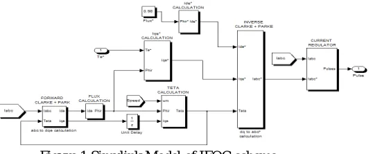
II. INDIRECT FIELD ORIENTATION CONTROL OF INDUCTION MOTOR
The indirect field oriented control consists of controlling the stator currents represented by a vector. This control is based on projections that transform a three phase time and speed dependent system into a two coordinate (d and q frame) time invariant system [8]. IFOC machines need two constants as input references: the torque component (aligned with the q coordinate) and the flux component (aligned with d coordinate).To implement indirect field orientation scheme first uses three-phase currents (a,b,c) i.e., Ias, Ibs, and Ics transformed into currents in the two-phase
orthogonal stator system (ds,qs) i.e., Ids and Iqs, i.e, Clark transform. Then this two-phase orthogonal system (ds,qs)
transform into rotating reference frame (de-qe). i.e, Park transforms [8] [11]. Complete algorithm is given below for indirect field orientation scheme [1][12]:
1. Measure the stator phase currents Ia, Ib, and Ic. These currents are feed to Clarke transformation module that
gives two components, Ids and Iqs, in stationary reference frame.
2. Transform the set of these two currents, Ids and Iqs, into rotating reference frame. This conversion called Park
transformation, and provides Ide and Iqe.
3. The rotor flux is computed by:
e m d r r L I ˆ Ψ = 1+τ
where,r r r L τ = R
.4. The rotor angle,
θ
e, required for coordinate transformation is computed by equation:
t
e sl act
0
θ =
ω +ω dt
5. The motor speed
ω
act
is compared with the reference speed
ω
ref
and the error produced is fed to the speed controller. The output of the speed controller is electromagnetic torque Te*.6. The quadrature stator current component reference is calculated by:
e* r e
q r r τ * L 2 2 I = ˆ
3 p R Ψ
7. The direct stator current component reference Ide* is obtained by:
e* r d m ˆ Ψ I I =
8. Ide* and Iqe*current references are converted into Ids* and Iqs*, current references in stationary reference frame
by using inverse Park transformation.
9. Ids* and Iqs* current references are converted into phase current references Ia*, Ib*, and Ic* by using inverse
Clarke transformation and fed to the current controller. After then controller processes the measured and reference currents to generate the gating signals.
SIMULINK model is shown in figure 1.
Figure 1:Simulink Model of IFOC scheme.
III. CONTROLLERS
ISSN (Print) : 2320 – 3765
ISSN (Online): 2278 – 8875
I
nternational
J
ournal of
A
dvanced
R
esearch in
E
lectrical,
E
lectronics and
I
nstrumentation
E
ngineering
(An ISO 3297: 2007 Certified Organization)
Vol. 5, Issue 9, September 2016
to controller. Perfect controlling of torque gives output to perfect speed response curve [6] [7]. The various type of controller such as conventional controller i.e. PI, PD and PID, fuzzy logic controller (FLC) and hybrid fuzzy-conventional controller i.e., FLC+PI, FLC+PD and FLC+PID are combining with IFOC to achieve the perfect response of speed curve. The reference speed of 120rad/sec is considered for all controllers. All this controllers are connected with the help of manual switch and select one controller manually at a time, and study the speed response in terms of rise time, settling time, overshoot, undershoot and peak time.
1. Conventional Controller: Conventional controller includes PI, PD and PID as shown in figure 2(a)(b)(c). All these controllers are closed loop/feedback controller along with IFOC. The difference of reference speed (
ref
ω
) and actual speed (ω
act), which is called the speed error (E
(s)), is given as input to the controller. The speed controller processes the speed error and gives torque value as an input. Then the torque value is fed to the limiter, which gives the final value of command torque to IFOC scheme [2] [3].(a) (b) (c)
Figure 2: Conventional Controller: (a) PI-controller (b) PD-controller and (c) PID-controller
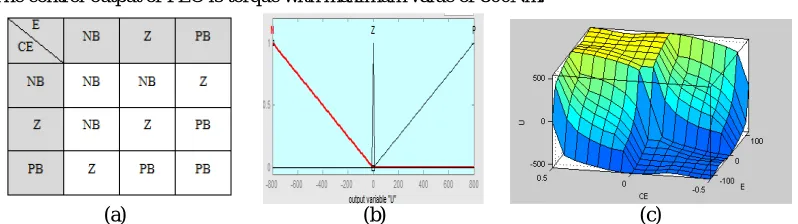
2. Fuzzy Logic Based Controller (FLC): The design of a Fuzzy Logic Controller requires the choice of Membership Functions. The membership functions should be select such that they cover the whole universe of discourse. It should be taken care that the membership functions overlap each other [7] [6] [1]. This overlapping is done in order to avoid any kind of discontinuity with respect to the changes in the inputs. To achieve perfect/finer control, the membership function near the zero regions should be made narrow as possible as shown in figure 3(b). Wider membership functions away from the zero regions provide faster response to the system. Hence, the membership functions should be adjusted as per your controller performance. After the appropriate membership functions are chosen, a rule base should be created as shown in figure 3(b). It consists of a number of Fuzzy If-Then rules that completely define the behaviour of the system. We implement 9 If-then rules as shown in figure 3(a).
The inputs to the Fuzzy Logic Controller are: 1) Speed Error (E).
2) Change in Error (CE) or derivative of speed error.
The control output of FLC is torque with maximum value of 800Nm.
(a) (b) (c)
Figure 3(a): Fuzzy rule-base table (b) output membership function (c) Rule view of rule-basefor controlling the speed of SCIM.
ISSN (Print) : 2320 – 3765
ISSN (Online): 2278 – 8875
I
nternational
J
ournal of
A
dvanced
R
esearch in
E
lectrical,
E
lectronics and
I
nstrumentation
E
ngineering
(An ISO 3297: 2007 Certified Organization)
Vol. 5, Issue 9, September 2016
(FPPI) controller [5]. The conventional speed controllers for indirect vector control of induction motor suffer from the problem of stability, these controllers such as PD or PID controllers show steady state error to remove the disadvantages of conventional and FLC i.e., steady-state error, and PI-controller i.e., overshoot and undershoot.
(a) (b) (c)
Figure 4(a): FLC+PI (b) FLC+PID and (c) FPPI Controller.
To take over the advantages present in both FL and PI controllers, a hybridization of FL and PI controllers, called fuzzy Pre-compensated Proportional Integral (FPPI) controller, is done and is used as a single controller. As shown in figure 4(c). In this controller, FL is used for pre-compensation of reference speed, which means that the reference speed signal (RS) is changed in advance in accordance with the rotor speed, so that a new modified reference speed signal is obtained and the main control action is performed by PI controller. Some particular features such as overshoot and undershoot happening in the speed response, which are obtained with PI controller can be removed and this controller is much useful to loads where the torque/speed of the motor varies every moment.
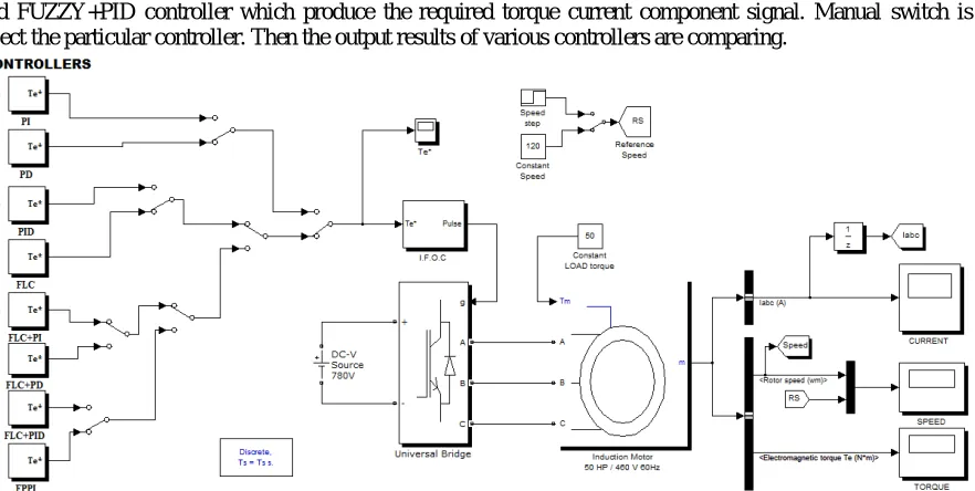
IV. SIMULINK MODEL
A complete SIMULINK model of proposed control system for SCIM is shown in Figure 5. The induction motor used
in this simulation is a 50 Hp, 460 V, 60 Hz, squirrel cage. The induction motor stator is fed by a current controlled three-phase inverter bridge. The IGBT/Diode is use as a power electronic element for the 3-phase Inverter Bridge, having 3 bridge arms. The motor speed is regulated by various controllers i.e., PI, PD, PID, FUZZY+PI, FUZZY+PD and FUZZY+PID controller which produce the required torque current component signal. Manual switch is use to select the particular controller. Then the output results of various controllers are comparing.
ISSN (Print) : 2320 – 3765
ISSN (Online): 2278 – 8875
I
nternational
J
ournal of
A
dvanced
R
esearch in
E
lectrical,
E
lectronics and
I
nstrumentation
E
ngineering
(An ISO 3297: 2007 Certified Organization)
Vol. 5, Issue 9, September 2016
V. RESULT AND DISCUSSION
The performances of all controllers are investigated while varying the load torque values. The maximum output torque is fixed for the entire controller and the other parameter is same for all the controller, only controller is change and according to this response of the controllers are study.
1. Speed response in no load and at reference speed 120rad/sec
The speed responses of SCIM under no load torque and at reference speed of 120 rad/sec. The computing time interval is 3sec for conventional controllers are shown in figure 6(a). And computing time interval for hybrid controllers are 0.5sec shown in figure 6(b) .In these figure pink line represent reference speed and yellow line represent the response curve.
(a) (b)
Figure 6: (a) Speed response of PID controller (b) FLC+PID controller, under NO LOAD.
Controllers Rise time (sec)
Settling time (sec)
Settling minimum
value
Settling maximum
value
Overshoot value
Peak value
Peak time (sec)
PI 0.2005 0.9520 108.0059 127.2863 6.0719 127.2863 0.4075
PD 0.2132 0.3396 108.0063 119.5210 0 119.5210 1.1663
PID 0.2010 1.9390 108.0110 127.8670 6.5559 127.8670 0.4566
FLC Only 0.3495 0.4481 108.0027 119.9098 0 119.9098 0.8749
FLC+PI 0.1999 0.2499 108.0141 120.0549 0.0458 120.0549 0.2592
FLC+PD 0.1999 0.2499 108.0141 120.3558 0.2965 120.3558 0.4000
FLC+PID 0.1999 0.2499 108.0141 120.0868 0.0723 120.0868 0.2803
FPPI 0.1999 0.2499 108.0114 120.0547 0.0456 120.0547 0.2587
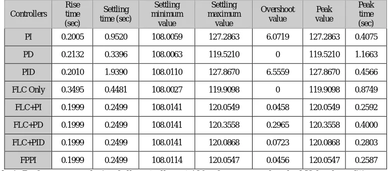
Table 1: Performance analysis of all controllers at 120 reference speed under NO load condition.
From above simulation results under no load torque condition, we conclude that the motor speed response for conventional controllers shows overshoot and deviation from reference speed and then return to the desire speed after some interval of time. Whereas Hybrid PI, PID and FPPI does not shows overshoot and deviation.
2. Load Torque of 50Nm and Reference Speed of 120 rad/sec
ISSN (Print) : 2320 – 3765
ISSN (Online): 2278 – 8875
I
nternational
J
ournal of
A
dvanced
R
esearch in
E
lectrical,
E
lectronics and
I
nstrumentation
E
ngineering
(An ISO 3297: 2007 Certified Organization)
Vol. 5, Issue 9, September 2016
(a) (b)
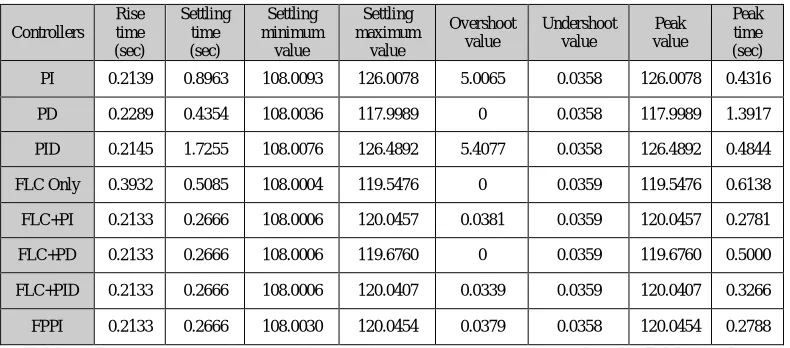
Figure: 7(a) Speed response of PI-controller (b) FLC+PI controller, in 50Nm constant load torque.
Controllers Rise time (sec)
Settling time (sec)
Settling minimum
value
Settling maximum
value
Overshoot value
Undershoot value
Peak value
Peak time (sec)
PI 0.2139 0.8963 108.0093 126.0078 5.0065 0.0358 126.0078 0.4316
PD 0.2289 0.4354 108.0036 117.9989 0 0.0358 117.9989 1.3917
PID 0.2145 1.7255 108.0076 126.4892 5.4077 0.0358 126.4892 0.4844
FLC Only 0.3932 0.5085 108.0004 119.5476 0 0.0359 119.5476 0.6138
FLC+PI 0.2133 0.2666 108.0006 120.0457 0.0381 0.0359 120.0457 0.2781
FLC+PD 0.2133 0.2666 108.0006 119.6760 0 0.0359 119.6760 0.5000
FLC+PID 0.2133 0.2666 108.0006 120.0407 0.0339 0.0359 120.0407 0.3266
FPPI 0.2133 0.2666 108.0030 120.0454 0.0379 0.0358 120.0454 0.2788
Table 2: Performance analysis of all controllers at 120 reference speed under 50Nm load torque.
We can easily notice that the motor speed response, under LOAD TOQUE condition, of conventional controller shows overshoot and deviation from reference speed. Whereas the hybrids PI, PID and FPPI controllers are fast response compare to conventional controllers and it does not shown overshoot and any deviation.
VI. CONCLUSION
This paper has successfully presented a Conventional and Hybrid controller for controlling a 50hp three-phase squirrel cage induction motor. We conclude that Hybrid controller has showed the combined advantages of a conventional controller and a FLC. Hybrid controller gives better performances in terms of rise time, overshoot, undershoot and settling time. Hybrid controller include FLC+PI, FLC+PID and FPPI having good response, but hybrid FLC+PD having peak time response is slower than other hybrid controller. Good torque response is obtained with hybrid controller at all time instants and speed response is better than FLC and PI controllers.
REFERENCES
[1]. Fattah, Ahmed, "Design and Analysis of Speed Control Using Hybrid PID-Fuzzy Controller for Induction Motors" (2015). Master's Theses. Paper 595.
[2]. Vivek Dutt and Rohtash Dhiman,”Performance Analysis of Induction Motor Using Artificial Intelligent Techniques” International Journal of Computer Science and Telecommunications [Volume 3, Issue 1, January 2012].
[3]. Anmol Aggarwal, J. N. Rai and Maulik Kandpal, “Comparative Study of Speed Control of Induction Motor Using PI and Fuzzy Logic Controller” IOSR Journal of Electrical and Electronics Engineering (IOSR-JEEE) e-ISSN: 2278-1676,p-ISSN: 2320-3331, Volume 10, Issue 2 Ver. I (Mar – Apr. 2015), PP 43-52.
[4]. Gauri V. Deshpande and S.S.Sankeshwari, “ Speed control of induction motors using hybrid PI plus fuzzy controller”, International Journal of Advances in Engineering & Technology, Nov-2013. ©IJAET ISSN: 22311963, Vol. 6, Issue 5, pp. 2253-2261.
ISSN (Print) : 2320 – 3765
ISSN (Online): 2278 – 8875
I
nternational
J
ournal of
A
dvanced
R
esearch in
E
lectrical,
E
lectronics and
I
nstrumentation
E
ngineering
(An ISO 3297: 2007 Certified Organization)
Vol. 5, Issue 9, September 2016
[6]. Hossein Ebadi Kalhoodashti and Dr. Mehdi Shahbazian, “Hybrid Speed Control of Induction Motor using PI and Fuzzy Controller” International Journal of Computer Applications (0975 – 8887) Volume 30– No.11, September 2011.
[7]. V. Chitra, and R. S. Prabhakar, “Induction Motor Speed Control using Fuzzy Logic Controller” ,World Academy of Science, Engineering and Technology 23 2006.
[8]. “Park, Inverse Park and Clarke, Inverse Clarke Transformations MSS Software Implementations User Guide” by MICROSEMI.
[9]. “Modren Power Electronics and Ac Drives” by Bemal K. Bose, 1st ed., Bernard Goodwin, Ed. USA: Prentice Hall, Inc., 2002.
[10]. F. Blaschke, "The Principle of Field Orientation as Applied to the New Transvector Closed Loop Control Systems for Rotating Machines,"
Siemens Review, vol. 39, no. 5, pp. 217-220, 1972.
[11]. “Clarke & Park Transforms on the TMS320C2xx”, Application Report Literature Number: BPRA048, TEXAS INSTRUMENTS.
[12]. Chaymae Laoufi, Ahmed Abbou And Mohammed Akherraz, “Comparative Study between Different Speed Controller Techniques Applied to the Indirect Field-Oriented Control of an Induction Machine-Performances and Limits” Electric Engineering Department, The Mohammadia School’s of Engineers, Mohammed V University Agdal, Avenue Ibn Sina, B.P 765, Agdal, Rabat, MOROCCO, Volume 10, 2015.
BIOGRAPHY
Mr. Bishwajeet Mondal- he received her B. Tech. Degree in Electrical and Electronics Engg. from CT Institute of Engineering., Management and Technology, PTU, Jalandhar, (Punjab) India, in 2011. At Present he is M.Tech scholar in Power system from Hindu College of Engineering, Sonipat (Haryana) India.
Mr. Ashwani Kumar- He received the B.E. and M.E. degrees in Electrical Engg. from Mahrishi Dayanand University Rohtak in 2003 and 2008 respectively. He is currently working towards the Ph.D with Department of Electrical Engineering UTTRAKHAND TECHINCAL UNIVERSITY Dehradun. His current research interest includes hybrid renewable energy system, Control theory and Wavelet analysis.