1
Performance of the Structural Analysis of Ford Car
Steering Rod
Malge Sangeeta Ganesh
1, G. P. Patil B.
2, N. A. Kharche.
3Department of Mechanical Engineering1, 2, 3, , S.Y.M.E. Mechanical-(CAD/CAM)1, Associate Prof. V.B.K.C.O.E., Malkapur 2, Asst. Prof. V.B.K.C.O.E., Malkapur 3,
Email: [email protected]
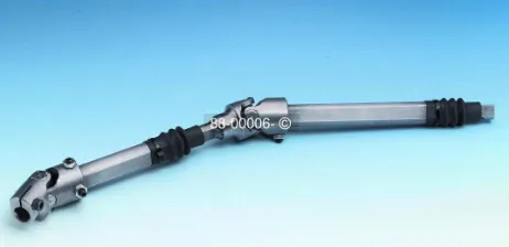
Abstract- Steering shaft/rod is an important part of overall steering system. It is a media between Steering wheel and steering box. Whoever there are many issues related to its function-ability occurs. Stresses developed in an object, design requirements at the joints, deformation in body due to vibrations, continuous twisting and loading these are the common one related to steering rod.
In this Paper Various Structural analyses such as Static-Structural, Modal Analysis of a steering rod are done. Static-structural analysis is capable to find out deformation in body in which Von-mises stress are calculated and this state that up to what extent the deformation in the rod occurs. while modal analysis is important in vibration point of view. i.e. Vibrations in body can be calculated up to what frequency the steering rod can sustain the load or Harmonic frequency of the body From above Optimisation of steering rod can be done. In This Paper I have done structural analysis of ford fiesta classic car steering rod to Optimise the Steering rod with better results than existing one.
Index Terms- Steering rod, Structural analyses, Modal Analysis, Deformation, Harmonic frequency, stress.
I. INTRODUCTION
The most conventional steering arrangement is to turn the front wheels using a hand–operated steering wheel which is positioned in front of the driver, via the steering column, which may contain universal joints (which may also be part of the collapsible steering column design), to allow it to deviate somewhat from a straight line. Other arrangements are sometimes found on different types of vehicles.
The steering system is a group of parts that transmit the movement of the steering wheel to the front, and sometimes the rear, wheels. The primary purpose of the steering system is to allow the driver to guide the vehicle. When a vehicle is being driven straight ahead, the steering system must keep it from wandering without requiring the driver to make constant corrections.
The steering system must also allow the driver to have some road feel (feedback through the steering wheel about road surface conditions). The steering system must help maintain proper tire-to-road contact. For maximum tire life, the steering system should maintain the proper angle between the tires both during turns and straight-ahead driving. The driver should be able to turn the vehicle with little effort, but not so easily that it is hard to control.
There are Following Types of Steering System
1.Rack-and-pinion Steering 2.Conventional Steering
.
II. RACK-AND-PINION STEERING SYSTEM
Rack-and-pinion steering transmits circular motion from the steering wheel to a pinion that meshes with teeth on a flat rack. The pinion moves the rack in a linear direction, steering the wheels. Rack-and-pinion steering can be found on cars, mini-vans and small SUVs. It is simpler and less expensive to produce than conventional steering systems.
1.Steering wheel 2.Steering Column 3.Rack and pinion 4.Tie Rod 5.Kingpin
3
III. CONVENTIONAL STEERING
Conventional steering transmits the circular motion from the steering wheel through a gear that moves an arm through a back-and forth arc, acting on a set of linkages to steer the wheels. It is also referred to as “re-circulating ball” or “worm gear” steering, for the type of gear it uses, or “parallelogram,” “trapezium,” or simply “linkage” steering, for the shape formed by the linkage set. This type of system can be found on most rear wheel drive cars, light trucks and full size vans.
3.1 Recirculating Ball Steering
Re-circulating-ball steering is used on many trucks and SUVs today. The linkage that turns the wheels is slightly different than on a rack-and-pinion system
Figure 3. R
ecirculating-ball steering
The recirculating-ball steering gear contains a worm gear. You can image the gear in two parts. The first part is a block of metal with a threaded hole in it. This block has gear teeth cut into the outside of it, which engage a gear that moves the pitman arm (see diagram above). The steering wheel connects to a threaded rod, similar to a bolt that sticks into the hole in the block. When the steering wheel turns, it turns the bolt. Instead of twisting further into the block the way a regular bolt would, this bolt is held fixed so that when it spins, it moves the block, which moves the gear that turns the wheels.
Figure 5. Worm gear steering system
Instead of the bolt directly engaging the threads in the block, all of the threads are filled with ball bearings that re-circulate through the gear as it turns. The balls actually serve two purposes: First, they reduce friction and wear in the gear; second, they reduce slop in the gear. Slop would be felt when you change the direction of the steering wheel -- without the balls in the steering gear, the teeth would come out of contact with each other for a moment, making the steering wheel feel loose.
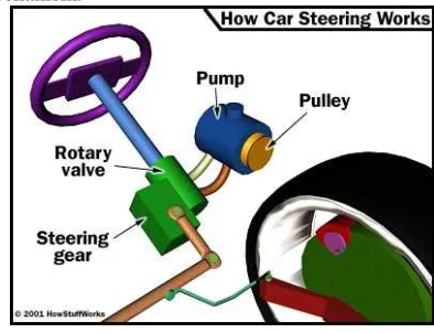
3.2 Power Steering
There are a couple of key components in power steering in addition to the rack-and-pinion or recirculating-ball mechanism.
Figure 4. Power steering system
The hydraulic power for the steering is provided by a rotary-vane pump (see diagram below). This pump is driven by the car's engine via a belt and pulley. It contains a set of retractable vanes that spin inside an oval chamber.
As the vanes spin, they pull hydraulic fluid from the return line at low pressure and force it into the outlet at high pressure. The amount of flow provided by the pump depends on the car's engine speed. The pump must be designed to provide adequate flow when the engine is idling. As a result, the pump moves much more fluid than necessary when the engine is running at faster speeds.
IV. PERFORMANCE OF STRUCTURAL ANALYSIS
4
4.1 Von-mises stress
Von Mises stress is widely used by designers, to check whether their design will withstand given load condition. Von mises stress is considered to be a safe haven for design engineers. Using this information an engineer can say his design will fail, if maximum value of Von Mises stress induced in the material is more than strength of the material. It works well for most of the cases, especially when material is ductile in nature.
Material used is High Chrome Steel
Young's modulus of chrome steel =2.2×10⁶Mpa Poission's Ratio =0.28
Density=7600Kg/m3
On the steering there is load of 30N.
Figure 6. Von mises stress.
Table1. Von mises Stress and Deformation Table
4.2 Performance of Modal Analysis
Modal analysis is important in vibration point of view. i.e. Vibrations in body are calculated up to what frequency the steering rod can sustain the load or Harmonic frequency of the body.
Use modal analysis to determine the vibration characteristics (natural frequencies and mode shapes) of a structure or a machine component while it is being designed.
It also can be a starting point for another, more detailed, dynamic analysis, such as a transient dynamic analysis, a harmonic response analysis, or a spectrum analysis.
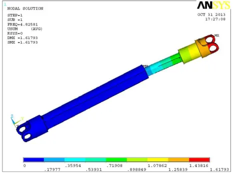
• In First Mode of Vibration
Maximum deformation of 1.61793 mm is obtained in this mode in the male shaft as shown in Fig. at the frequency value of 4.8251 Hz. The deformation is negligible in this mode.
Figure 7. Behaviour of rod in First Frequency set
• In Third mode of vibration
The frequency value is increasing with slight increment in deflection. This will affect the performance of steering rod
Sir. No. Nature Values
1. Maximum
Deformation
0.03067 mm
2. Minimum
stress
0.008166 MPa
3. Maximum
Stress
5
and its twisting. The values obtained in this mode are 6.42035 Hz frequency with 1.25014 mm deflection.
Figure 8. Behaviour of rod in Third Frequency set
• In Fifth Mode of Vibration
Here the maximum frequency with maximum deformation is shown in Fig 2.2. Above this frequency value shaft may damage due to maximum deformation. The maximum deformation of 2.20442 mm is obtained on frequency value of 39.66 Hz.
Figure 9. Behaviour of rod in Fifth Frequency set
V. CONCLUSIONS:
In this structural analysis is done to find the maximum deformation of the steering rod and stresses in the steering rod and it is noted that the deformation is negligible and the stresses by von-mises stress are below the yield point stress so the steering rod is safe.
Maximum deformation occurs at the corner points of the circular hole at both the ends of the rod and the stresses are also maximum at the corner points.
Modal analysis is done to calculate the Harmonic Frequency of the rod. The frequencies of the rod are calculated in five sets. In all five stages behaviour of the rod is different i.e. it varies from 1Hz to 39.66Hz. From this it is clear that Harmonic frequency is 39.66Hz. Further this frequency can be used to do the Harmonic analysis of the steering rod and for Optimisation.
.
VI. REFERENCES:
[1] Leslie Rayner (October 2004), Steering Design for a Formula SAE-A Open Wheel Race Car.
[2] X. Claeys, C. Canudas-de-wit, H. Bechart Modeling and control of steering Actuator for Heavy Duty Vehicles. [3] Tae Hee, Lee Byung Ryul, Ham Seong Oh, Hong
Advanced Safety CAE Team / Hyundai Motor Co. Korea Paper No. 11-0262, Study on steering Column Collapse analysis using detailed FE Model.
[4] Matthew Fulmer Reducing Free Play in an Automotive Steering System.
[5] CheeFai Tan, Ranjit SinghSarban Singh, V.K. Kher and B.T . Tan, Integrated Design Research Group (IDEA), Integrated Steering System Design for Bus Driver Drowsy Behavior Change.
[6] [Naresh Kamble and S.K. Saha Department of
Mechanical Engineering, Indian Institute of