ISSUES OF ITERATIVE MDA-BASED
SOFTWARE DEVELOPMENT
PROCESSES
MASTER THESIS
Author: Geert Vos
Thesis for the masters degree Computer Science.
Department of Computer Science, University of Twente, the Netherlands.
Getronics PinkRoccade Apeldoorn, 5-4-2008
Supervising committee: dr. I. Kurtev (first supervisor) prof. dr. ir. M. Akşit
dr. ir. K. G. van den Berg A. Goknil, MSc.
I
TITLE PAGE
Title: Issues of iterative MDA-based software development processes
Author: Geert Vos BSc. Student number: S0107670
MSc program: Computer Science Track: Software Engineering
Institute: University of Twente, the Netherlands
Faculty: Electrical Engineering, Mathematics and Computer Science
Company: Getronics PinkRoccade Fauststraat 3
7323 BA Apeldoorn The Netherlands
http://www.getronicspinkroccade.nl
Date: 5-4-2008
Supervising committee:
dr. I. Kurtev (first supervisor) University of Twente
prof. dr. ir. M. Akşit University of Twente
dr. ir. K. G. van den Berg University of Twente
A. Goknil, MSc. University of Twente
ir. J.W. van Veen Getronics PinkRoccade
drs. H. Nieboer Getronics PinkRoccade
II
ABSTRACT
Since the beginning of computer programming people have been raising the level of abstraction. The latest step in raising the level is probably Model Driven Engineering (MDE). In MDE, models are not only used to assist in the development process, instead they are the primary artifacts. Model Driven Architecture(MDA) is a specific form of MDE in which industry standards are adopted. MDA is based on the following standards: Unified Modeling Language (UML), XML Meta Interchange (XMI), Query/View/Transformation (QVT), Object Constraint Language (OCL) and Meta Object Facility (MOF).
Currently, there is a lack of knowledge and experience in applying MDA in an iterative development process. With this project we try to obtain that knowledge and experience by conducting a case study. In this case study an existing software system is rebuilt using the MDA approach and the Rational Unified Process (RUP). By rebuilding this system we tried to answer two questions, what are the critical issues of an iterative MDA-based development process and what are the critical issues with respect to maintenance of an MDA-based product.
The major parts of the case study are the rebuilding of a small-sized software system using RUP and MDA, and applying maintenance to that system. The first part of the case study consists of four phases: the inception phase, elaboration phase, construction phase and the transition phase. In the inception phase we developed an architecture for the system and an architecture for the MDA approach. Both architectures were tested in the elaboration phase. In this phase the first use-case was implemented. Two models were created to implement this use-case, an ASP and a C# meta-model. We also created two UML profiles. A profile for the domain models and a profile for user-experience models. The meta-models and profiles were developed in the elaboration phase. Based on the UML profiles, two models were made. A domain model, modeling the business objects of our system and an user-experience model which models the user interface and navigation of our system. The UML models were transformed into C# and ASP models using model transformations written in QVT. In the construction phase the second use-case was implemented. The implementation required adaption of the meta-models and transformations. Also a new meta-model was introduced: Sitemap. This meta-model is used to model the main menu of the system at platform specific level. The last phase of this project, the transition phase, consisted of two iterations. In the first iteration the rebuilt system was tested and deployed. In the second iteration we applied maintenance to the system. We implemented four change requests to observe the impact of the MDA approach with respect to maintenance.
During the evaluation of this case study a number of issues were observed. The following issues were identified: “Model and meta-model co-evolution is difficult”, “Structural incongruence increases transformation complexity”, “Lack of object orientation in QVT”, “Transformation composition”, and “Model composition is difficult”. A description and a solution (if known) is provided for each issue.
III
ACKNOWLEDGEMENTS
IV
LIST OF ABBREVIATIONS
Abbreviation Meaning
ASP Active Server Pages
CIM Computational Independent Model
CMOF Complete MOF
CR Change Request
DSL Domain Specific Language
EBNF Extended Backus Naur Form
EMF Eclipse Modeling Framework
EMOF Essential MOF
EPF Eclipse Process Framework
GPL General Purpose Language
MDA Model Driven Architecture
MDE Model Driven Engineering
MOF Meta Object Facility
OCL Object Constraint Language
OMG Object Management Group
OPENUP Open Unified Process
OpenUP Open Unified Process
ORM Object Relational Mapper
PIM Platform Independent Model
POC Proof of Concept
PSM Platform Specific Model
QVT Query/View/Transformation
RUP Rational Unified Process
SQL Structured Query Language
UC Use Case
UML Unified Modeling Language
UX User Experience
V
LIST OF FIGURES
Figure 1: Thesis outline ... 16
Figure 2: Meta-level example ... 19
Figure 3: Meta-level architecture ... 19
Figure 4: Meta-model transformation pattern (Kurtev & van den Berg, Building Adaptable and Reusable XML Applications with Model Transformations, 2005). ... 20
Figure 5: MDA layered model structure ... 24
Figure 6: Simplified MOF structure ... 24
Figure 7: QVT layered architecture ... 27
Figure 8: Software life cycle ... 29
Figure 9: Simplified schema of the waterfall model ... 30
Figure 10:Schema of the Iterative model ... 31
Figure 11: Phases and iterations of RUP ... 33
Figure 12: OpenUP Structure (Balduino, 2007) ... 36
Figure 13: Project phases ... 42
Figure 14: Project plan ... 42
Figure 15: Three tier architecture of Arend ... 44
Figure 16: Schematic application structure ... 45
Figure 17: Schematic view of models and transformations ... 46
Figure 18: Modeling layers ... 46
Figure 19: Domain model snippet ... 47
Figure 20: Examples of the persistency profile ... 48
Figure 21: User experience diagram of a form ... 49
Figure 22:Single form example screen ... 49
Figure 23: User experience diagram of a content bundle ... 49
Figure 24: Example of a content bundle ... 49
Figure 25: User experience diagram of a multiple input form ... 50
Figure 26: Multiple form example screen ... 50
Figure 27: Navigation example ... 50
Figure 28: Snippet of the menu structure ... 51
Figure 29: The modeled menu structure ... 51
Figure 30: A part of the C# meta-model ... 52
Figure 31: A part of the ASP meta-model ... 53
Figure 32: Sitemap meta-model ... 54
Figure 33: Transformation overview ... 55
Figure 35: Pattern for the user experience to C# transformation ... 56
Figure 36: Pattern for the user experience to Sitemap transformation ... 56
Figure 37: Pattern for the domain model to C# transformation ... 57
Figure 38: Evaluation map ... 62
Figure 39: Transformation package elaboration phase ... 65
Figure 40: Transformation package construction phase ... 66
Figure 41: Transformation pattern with changes in meta-model A ... 71
Figure 42: Transformation pattern for poor inheritance issue ... 75
Figure 43: Pattern for the issue of transformation composition ... 76
Figure 44: Model composition pattern ... 78
Figure 45:Pattern for the issue of model composition ... 78
Figure 46: Full domain model ... 95
Figure 47: User Experience model for Use-case 1 ... 97
Figure 48: User experience model for Use-case 2, part 1 ... 99
Figure 49: User experience model for Use-case 2, part 2 ... 100
Figure 50: Extra user experience model for testing purposes ... 100
VI
LIST OF CODE FRAGMENTS
Code section 1: A sample of OCL ... 26
Code section 2: A sample of QVT Operational Mappings ... 27
Code section 3: Example C# property ... 57
Code section 4: Example C# collection property ... 58
Code section 5: Illustration of the QVT Operational Mappings language ... 58
Code section 6: Illustration of the Xpand template language ... 59
Code section 7: Hierarchical complexity in QVT ... 73
Code section 8: QVT increased number of mappings ... 73
Code section 9: Polymorphism in QVT ... 74
Code section 10: Hardcoded polymorphism in QVT ... 74
Code section 11: Poor inheritance in QVT ... 75
Code section 12: Transformation composition (Object Management Group, 2007)... 76
TABLE OF CONTENTS
I Title page ... 3
II Abstract ... 4
III Acknowledgements ... 5
IV List of Abbreviations ... 6
V List of figures ... 7
VI List of code fragments ... 9
Table of Contents ... 10
1 Introduction ... 13
1.1 Background ... 13
1.2 Problem statement ... 14
1.3 Research questions ... 14
1.4 Approach ... 15
1.5 Contributions ... 15
1.6 Thesis outline ... 16
2 Model Driven Engineering ... 17
2.1 Models and modeling ... 17
2.2 Model Driven Engineering ... 18
2.3 Meta-modeling ... 18
2.4 Model Transformation ... 20
2.5 Domain Specific Languages ... 22
2.6 Model Driven Architecture ... 23
2.7 Meta Object Facility ... 24
2.8 Unified Modeling Language ... 25
2.9 Object Constraint Language ... 26
2.10 Query View Transformation ... 26
2.11 Conclusion ... 27
3 Software development processes ... 29
3.1 Software Life Cycle ... 29
3.2 Waterfall model ... 30
3.3 Iterative Model ... 30
3.4 Rational Unified Process... 31
3.4.1 Background ... 31
3.4.2 Phases ... 32
3.4.3 Roles ... 34
3.5 Open Unified PRocess ... 35
3.5.1 Description ... 35
3.5.2 Phases ... 36
3.5.3 Roles ... 36
3.5.4 OpenUP and MDA ... 37
3.6 Customization of RUP and OpenUP ... 37
3.7 Maintenance and Evolution ... 38
3.8 Conclusion... 38
4 Case study ... 41
4.1 Description ... 41
4.2 Development plan ... 41
4.3 Development Environment ... 43
4.4 Application Architecture ... 44
4.5 Model Architecture ... 45
4.6 Platform Independent Models... 46
4.6.1 Domain Model ... 47
4.6.2 User Experience Model ... 48
4.7 Platform Specific models ... 51
4.7.1 C# Meta-Model ... 52
4.7.2 ASP Meta-Model ... 53
4.7.3 Sitemap Meta-Model ... 53
4.8 PIM to PSM Transformations ... 54
4.8.1 Transformation Architecture ... 54
4.8.2 User Experience Model Transformations ... 55
4.8.3 Domain Model Transformations ... 56
4.8.4 QVT Transformations ... 58
4.9 Code Generation ... 58
4.10 Conclusion... 59
5 Evaluation... 61
5.1 Software Development Process ... 61
5.1.1 Inception phase ... 62
5.1.2 Elaboration phase ... 63
5.1.3 Construction phase ... 64
5.1.4 Transition phase Iteration 1 ... 67
5.1.5 Transition phase Iteration 2 ... 67
5.3.1 Model and Meta-model co-evolution is difficult ... 71
5.3.2 Structural incongruence increases transformation complexity ... 72
5.3.3 Lack of object orientation in QVT ... 74
5.3.4 Transformation composition ... 75
5.3.5 Composing models is difficult ... 77
5.4 Conclusion ... 79
6 Conclusions and Future Work ... 81
6.1 Project summary ... 81
6.2 Iterative MDA-based development ... 82
6.3 MDA and Maintenance ... 82
6.4 Immaturity of tools ... 83
6.5 Future Work ... 83
6.5.1 Model composition ... 83
6.5.2 Transformation composition ... 84
6.5.3 Model Meta-model co-evolution ... 84
6.5.4 Model Driven Development Process ... 84
Bibliography ... 85
Appendix A Problem analysis results ... 89
Appendix B Transformation patterns... 91
Appendix C Domain Model ... 95
Appendix D User Experience UC1 ... 97
Appendix E User Experience UC2 ... 99
Chapter 1
1
INTRODUCTION
This chapter provides an introduction to the thesis and the backgrounds of the project. This chapter creates a context for the project and states the problem statement and research questions.
1.1
BACKGROUND
Since the beginning of computer programming people have been raising the level of abstraction. The first assembler languages we used to simplify computer programming. Instead of directly programming in machine language, assembler raised the level of abstraction to instructions and mnemonics. The next big step in raising the level of abstraction was taken by John Backus in 1954. He and his team invented Fortran, which was the first high level programming language. In the 1960’s the first Object Oriented programming languages appeared. Object orientation was again a new level of abstraction to simplify computer programming.
The latest step to raise the level of abstraction is probably Model Driven Engineering (MDE) (Kent, 2002). This is currently a topic that has the interest of researchers and companies. The promise of MDE to raise the level of abstraction in software development makes it an interesting topic. It is a common practice to create models to assist developers with the implementation of an application. These models are often used as documentation and as guidelines for development but are not directly involved in the production of an application. In MDE the models are not only used to assist development, but the models form the backbone of the development process. In the view of MDE everything is a model including the source code.
Many companies are currently interested in Model Driven Architecture (MDA) (Object Management Group, 2003) as an approach for applying MDE principles. MDA is proposed by the Object Management Group (OMG) and is supported by industry standards like UML (Object Management Group, 2007), MOF (Object Management Group, 2006), OCL (Object Management Group, 2003) and XMI (Object Management Group, 2007). MDA, as described by the OMG, is one of the methods to apply MDE.
Getronics PinkRoccade is one of the larger players on the software market and provides services ranging from workplace management to the development, installation and maintenance of software systems. This project is carried out within the business unit Microsoft Application Services. This business unit is specialized in the development and maintenance of software systems based on Microsoft products and technology.
1.2
PROBLEM STATEMENT
Getronics PinkRoccade is interested in applying MDA in practice, but there are many problems that needs to be solved before MDA can be put to practice. Getronics PinkRoccade has done research on MDA in the past and also has a department working on model driven engineering. Companies like Getronics PinkRoccade often use iterative software development processes to minimize the risk in software development. At the start of this project we held a problem analysis session for the following problem: “MDA is not applied on a large scale in the software industry”. Starting from this general problem the stakeholders of this project identified a number of causes for this problem. The results from the session were send to all stakeholders. Each of the stakeholders was asked to divide 10 points over the different causes. The highest ranked causes were selected as input for this project:
MDA is not iterative
Lack of experience with MDA and maintenance
It is unclear whether models are easier to maintain than source code
These problems are the motivation for this master project. The results of the problem analysis session are available in Appendix A.
1.3
RESEARCH QUESTIONS
There is currently no commonly accepted software development process to apply model driven development. Some effort has been made to create a development process (Eclipse Process Framework OpenUP/MDD, 2006). There is also some work done on combining MDA with the Rational Unified Process (Brown & Conallen, 2005). Still there is no common agreement on what development process to use. A development process like RUP is an iterative development process and nowadays considered a best practice by many companies. Combining MDA with RUP seems a logical step, but it is unclear if this works in practice. A closer look on MDA reveals a more classic waterfall software development process (Wegener, 2002). This contradicts with the iterative approaches we use today.
Another interesting question is related to maintenance. The promise of MDA is to raise the level of abstraction. This would both lead to faster software development as an increase in maintainability. The general idea is that models are easier to maintain then code. Instead of changing 10 scattered lines of code, changing a single property in a model seems easier. But what are the issues regarding to MDA and maintenance?
The following two research questions forms the basis for this study:
1.4
APPROACH
There is currently little knowledge about how MDA can be applied in practice and what issues will be encountered if one combines an iterative development process with MDA-based development. With this thesis we want to obtain both operational knowledge and contribute to science. The operational knowledge is recorded in the form of this thesis and our case study. We provide an example of how MDA can be applied in an practical environment instead of a lab experiment. Our contribution to science is an overview of the issues that at least must be solved before MDA can be considered a mature technology.
This study has the following structure. The main part of our study is a case study. In the case study we will investigate how MDA can be applied in practice in an iterative software development process. The case study is based on a development project carried out by Getronics PinkRoccade. We will rebuild a part of the system they built in the Arend project. This system is a data centric web-application. In this study we rebuild the system using RUP as the development process and MDA to implement the system. The case study is documented in the form of plans and evaluations. The evaluations from the project are used in the second part of the study. In the second part we analyze the issues we have observed during our case study. For each of the issues we will provide a clear description of the problems, examples to illustrate the problems and a possible solution if there is a known solution.
1.5
CONTRIBUTIONS
The contributions can be summarized as follows:
Operational knowledge of MDA
An important part of this study is to provide knowledge and experience with MDA and iterative software development. We provide this knowledge in multiple forms. The most important form is this thesis. It describes our work and provides an evaluation of the project.
An overview of issues in the field of MDA
Because we carried out our project in an industrial setting we provide a different view of MDA. Researchers tend to focus on small problem areas and use laboratory experiments to verify hypothesis. During this case study we encounter practical problems that may not have been occurred in laboratory experiments.
More specific knowledge about MDA and iterative development
There is currently a lack of knowledge in applying MDA in an iterative fashion. With this case study we investigate what the implications are of combining MDA with an iterative development process. We use RUP as our iterative development process because it is an commonly accepted development process.
An example case of how MDA can be applied
1.6
THESIS OUTLINE
The structure of this thesis is as follows. In chapter two the most important concepts and theoretical backgrounds of model driven engineering are laid out. The basics of the Rational Unified Process and the Open Unified Process are explained in chapter three. We used RUP as the software development method to develop our case. In chapter four the case study itself is described. In this chapter the architecture and design of the system are described in detail. All meta-models, models and transformations used to develop the system are part of it. In chapter five the development process is described. This chapter is like a log book of the project and contains the evaluations for each of the phases in the development process and a list of issues. In the last chapter, chapter six we write down our conclusions, recommendations and future work.
Chapter 1: Introduction
Chapter 2: Model Driven Engineering
Chapter 3: Software Development Processes
Chapter 4: Case study
Chapter 5: Evaluation
Chapter 6: Conclusion
Readers with MDA experience may skip
chapter 2 Readers with experience
on RUP and OpenUP may skip chapter 3
Figure 1: Thesis outline
Chapter 2
2
MODEL DRIVEN ENGINEERING
This chapter gives an overview of the important concepts of model driven engineering. We explain these concepts and provide a theoretical background for model driven engineering. For most of the concepts we describe in this chapter there are no common accepted definitions. In this chapter we will define the concepts as they are used in this thesis.
2.1
MODELS AND MODELING
Models are used for various purposes. We can enumerate many different models: miniature models, weather models, mathematical models, economic models and of course UML models. The word model has its roots in Latin. The Latin word modulus means “a small measure” but there is no single definition of the word model. Actually, the dictionary (Mariam Webster) gives over 15 different meanings of the word model. The OMG defines a model with the following statement:
“A model of a system is a description or specification of that system and its environment for some certain purpose. A model is often presented as a combination of drawings and text. The text may be in a modeling language or in a natural language.” (Object Management Group, 2003)
The definition from OMG describes a model as it is used in the context of MDA but it does not capture the fundamental concept of a model. For people with knowledge about modeling software systems, the definition from OMG describes how we often look at models. However, we need a more precise definition of a model. The following definition provides a more fundamental definition of a model:
“A model is a simplification of a system built with an intended goal in mind. The model should be able to answer questions in place of the actual system.” (Bézivin & Gerbé, 2001)
There is no general definition for the word model. In this thesis we use the definition from (Bézivin & Gerbé, 2001) because it defines a model in a broad sense. The models we are interested in are models that can be expressed in a modeling language.
“The process of construction or modification of a model.” (American Institute of Aeronautics & Astronautics, 1998)
2.2
MODEL DRIVEN ENGINEERING
The term Model Driven Engineering (MDE) was introduced by Stuart Kent (Kent, 2002) and is used to refer to the general idea to use models as first class entities in software development. In MDE, models play a central role in the development process. Models provide both an abstract description of the system under development as they can represent the source code. In the literature one may find other terms such as Model Driven Software Development or Model Driven Development. All terms refer to the general idea of MDE. In this study we use the term MDE. The key aspect of MDE is that models no longer play a role as design tool or as reference. Instead, models form the basis of the development process. Different models can be used to describe a system and model transformations can be used to provide the semantics for these models.
One advantage of MDE is that it raises the level of abstraction in software development. By defining a system on a more abstract level, the complexity of designing systems can be reduced. The higher level of abstraction enables developers to concentrate on the important aspects of a system and forget about implementation details. Another advantage of MDE is that MDE forces developers to explicitly specify the system. If a model is used as an image to help designing the system, not all details have to be modeled. If a models is used to generate the code, the model should be complete.
2.3
META-MODELING
In MDE models are based on a meta-model. For example there is a UML meta-model that expresses UML class diagrams. The definition of meta-model used in this thesis comes from (Seidewitz, 2003):
“a meta-model is a model of models expressed in a given modeling language”.
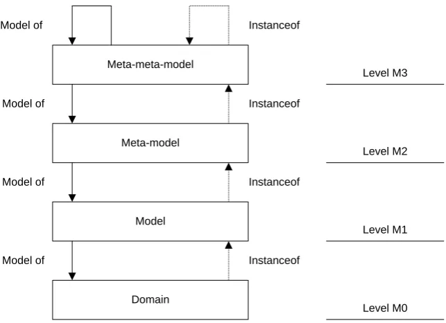
A model is a model that defines the constructs which can be used to express models. A meta-model defines the structure of a meta-model and the possible relations between the meta-model elements. To be more precise, a meta-model defines the abstract syntax of a modeling language. Every model has a meta-model. Java programs have the Java grammar as their meta-model, and the Java grammar has a EBNF description as its meta-model (see Figure 2). Models and meta-models have a class-instance relationship.
Figure 2: Meta-level example
In Figure 3, the levels are numbered. Level M0 refers to the domain that is being modeled. Level M1 refers to the model of the domain where level M2 is the meta-model and level M3 is the meta-meta-model. Every layer is an instance of layer M+1.
In theory the number of levels can be infinite, but a four level architecture is enough in practice. In this case, level M3 is self-descriptive. Level M3 can be specified using M3. In the example above (see Figure 2), EBNF is used to describe the abstract syntax (and in this case also the concrete syntax) of EBNF. The intuition behind the self-descriptive layer is quite elegant. In level M0 we have our domain which we model in M1. M2 is the language we use to give the abstract syntax to the modeling language and we have a language to describe the abstract syntax in M3. If this language is designed to describe the abstract syntax of a language it should be possible to describe itself (Kurtev, 2005).
The abstract syntax of a modeling language plays an important role in MDE. Tools, transformation languages and code generators can benefit from the fact that they are based on the same abstract syntax. The concrete syntax, the actual representation of a model, plays a less important role. It is considered a good practice to decouple the concrete syntax from the abstract syntax. This makes it possible to provide multiple concrete representations of the same model, for instance both a graphical and a textual representation. The concrete syntax is of course of great importance for the people who work with the models. A good concrete syntax is easier to work with and has a better readability and will improve the usage of the models (Object Management Group, 2003) .
2.4
MODEL TRANSFORMATION
Model transformations form a large part of MDE. The transformations are the main driver in the development process. Transformations can be used to convert one model into another model or to combine models. The term model transformation is a broad term. In this thesis we define a transformed into one or more constructs in the target language” (Kleppe, Warmer, & Bast, 2003).
This definition, however, states that we transform one model into one other model. As discussed in (Mens, Czarnecki, & Gorp, 2005) it should be possible to define transformations that transform multiple models into one model, multiple models into multiple models and one model into multiple models.
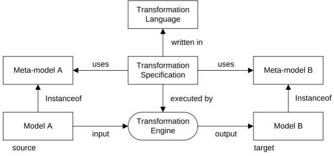
Figure 4: Meta-model transformation pattern (Kurtev & van den Berg, Building Adaptable and Reusable XML Applications with Model Transformations, 2005).
In the literature different types of transformations are identified (Mens, Czarnecki, & Gorp, 2005) (Czarnecki & Helsen, 2003). These includes transformations between models with the same meta-model called endogenous transformations and transformations with different meta-models called exogenous transformations. In the literature one can find a difference between model to model (m2m) and model to text(m2t) transformations. There is a small difference between those types of transformations. The difference can be identified when we look to the nature of the transformation. In a model to model transformation a mapping between the meta-models is defined while transformation templates are used for m2t. The output produced by m2t transformations can be seen as a model with an implicit meta-model while the output of the m2m transformation has an explicit meta-model. Most m2t transformations are exogenous transformations. In this case the generated text is on a more concrete abstraction level than the source model. However, endogenous m2t transformations also exist. Generating Java source code from a Java abstract syntax tree is an example of this. In this thesis we will make the distinction between m2t and m2m transformations for the sake of readability but conceptually difference is minimal.
Another distinction between types of transformations is the distinction between horizontal and vertical transformations. A horizontal transformation is a transformation where the input and output models have the same level of abstraction. An example of a horizontal transformation can be refactoring. With refactoring we only change the structure of the code. Vertical transformations transform a model to a model of a higher or lower abstraction level. An example of a vertical
Transformation languages come in many forms. Just like programming languages can be classified, we can classify transformation languages based on how they allow the programmer to express the transformation. The two most distinct types are operational and declarative languages. Declarative languages focus on what must be transformed into what. Declarative languages seem to be the most promising and there is a solid formal basis for these languages. It is easier to implement bi-directionality. These languages are easier to use because the engine that executes the transformation determines the execution ordering and model traversal. An operational (also called imperative) language focuses on how the transformation must be applied, giving the programmer a tool to precisely define the execution order and fine grained control over the transformation. As a result of this, transformations expressed in an operational language are often larger and more complex. Other types of languages could also be interesting to use, like graph transformations and logical languages (Mens, Czarnecki, & Gorp, 2005). A special type of language is the hybrid language. Hybrid languages are a mix of different types, usually with imperative and declarative constructs.
Examples of transformation languages are Stratego (Visser, 2004), KerMeta (Chauvel & Fleurey, 2007), Tefkat (Lawley), ATL (Allilaire, Bézivin, Jouault, & Kurtev, 2006) and QVT (Object Management Group, 2007). Stratego is a transformation language that is used in combination with XT. This bundle is called Stratego/XT. Stratego is a transformation language based on term rewriting. KerMeta is an abbreviation of “Kernel Metamodeling” and is a combination of a modeling and transformation
1
language. The language can be used to create models, to put restrictions on models and to transform models. Tefkat, ATL and QVT are all implementations of OMG's MOF Query/Views/Transformations RFP. QVT was finally adopted as the standard by the OMG.
A special type of transformation is currently gaining the interest from the research community: model composition. When we want to combine multiple source models into one target model this is called model composition. Model composition is a special form of transformation because it does not transform a model. However, it combines multiple models into one (Kurtev & Didonet Del Fabro, 2006) (Pastor, 2006).
2.5
DOMAIN SPECIFIC LANGUAGES
Computer scientists have always been working on languages. Even before the first computers were build, scientists were thinking of a way to program the hypothetical machines2. Currently a large variety of programming languages exist. Some of them such as Java, C# and C++ are more generic; some of them such as Cobol and Fortran are more specific. This section gives an introduction to domain specific languages. With domain specific languages we mean languages that are built to solve problems in a small problem domain. Their counterparts, generic programming languages, are built to solve problems in a larger problem domain. Of course, the terms generic and specific are relative. One language is more specific than another language. DSLs are not a new concept in computer science. Many engineers already use DSLs in their daily work without referring to them as a DSL. SQL is a nice example of such a DSL. It is a limited language which can only be used to query databases. Therefore, it is impossible to use SQL to create a socket connection and transfer a file. Since SQL has a specific domain it can provide a simple syntax which enables the programmer to specify complex queries with low overhead. Another example of a DSL is a configuration file or an EBNF grammar (Kurtev, Bézivin, Jouault, & Valduriez, 2006).
In this thesis we will use the following definition for DSLs:
“A domain-specific language is a programming language or executable specification language that offers, through appropriate notations and abstractions, expressive power focused on, and usually restricted to, a particular problem domain” (Deursen, Klint, & Visser, 2000).
DSLs can be implemented in a number of ways. One could use standard language engineering tools like ANTLR to build an interpreter or compiler and generate a large part of the implementation. The advantage of this approach is that you can actually implement the language without having to do any concessions on the language. With complete power over the language you can implement a complex type system, type checker, error checking and optimizations. The drawbacks on the other hand are the costs of the implementation and less reusability. Another approach could be to implement the DSL using special language constructs. Some general purpose programming languages like Ruby allow the programmer to implement a DSL on top of the base language. When you build a DSL based on an existing base language, one could use macros which are fed to a preprocessor. The preprocessor then translates the macros into constructs of the base language. One advantage of this approach is that the compiler is able to detect errors but the disadvantage is that error messages are given at the level of the base language. Sometimes even an existing compiler or interpreter can be extended to support a DSL. The Tcl interpreter is an example of this approach (Mernik, Heering, & Sloane, 2005) (Deursen, Klint, & Visser, 2000).
2
A modern approach is to use aspect oriented programming (Elrad, Filman, & Bader, 2001) to weave the DSL code into the base code. An example of this approach can be found in (Oever & Vos, 2007) where a DSL is described to specify user profiles for applications. The profiles are then woven into the code by using an aspect oriented approach.
2.6
MODEL DRIVEN ARCHITECTURE
The Object Management Group developed MDA as an approach for MDE based on industrystandards and with the main focus on platform independence. According to OMG, MDA provides an approach for specifying the system and its behavior independently of the platform that supports it and for specifying the platform itself (Object Management Group, 2003).
OMG describes a system as:
“We present the MDA concepts in terms of some existing or planned system. That system may include anything: a program, a single computer system, some combination of parts of different systems, a federation of systems, each under separate control, people, an enterprise, a federation of enterprises…”
OMG describes a platform as:
“A platform is a set of subsystems and technologies that provide a coherent set of functionality through interfaces and specified usage patterns, which any application supported by that platform can use without concern for the details of how the functionality provided by the platform is implemented”
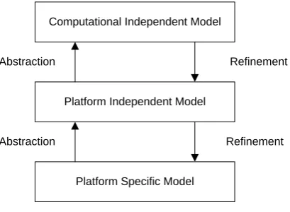
The main purpose of MDA is to provide platform independence and the different models used in MDA reflect this thought. In MDA there are three types of models: the Computational Independent Model (CIM), the Platform Independent Model (PIM) and the Platform Specific Model (PSM).
The CIM is the model that describes the systems requirements without any references to a particular technology or technique and it does not show how the system is implemented. The CIM shows the systems in its environment and helps presenting what the system should do. The CIM is not widely used because of the vague definition of what it actually should be. The model is also not directly used to create a PIM. However, there must be a clear relation between CIM and PIM.
The PIM is an important part of MDA. It describes the system without referring to the platform and thus gives a platform independent representation of a system. This model is the first step to create a system. The PIM can be transformed into a PSM using model transformations.
The PSM models provide information about how the system is implemented and its relation to the platform. A PSM contains the information from the PIM with specific details about the target platform. For example, a PIM may contain a concept with properties and one of the properties is whether it should be persistent or not. The PIM does not contain information about how the concept should be persisted but when the PIM is transformed to the PSM for a J2EE platform, the concept will be mapped to a Java Bean with the proper annotation for the persistence API3.
3
Computational Independent Model
Platform Independent Model
Platform Specific Model
Refinement
Refinement Abstraction
Abstraction
Figure 5: MDA layered model structure
Figure 5 shows the types of models and the relations between them. Each level represents a type of models, not one model. The refinement arrows indicate that a CIM can be refined to a PIM and that a PIM can be refined to a PSM. This refinement step is not necessarily one transformation step but it can be specified in multiple transformation steps. The abstraction arrows indicate that a PIM is more abstract than the PSM and the CIM is more abstract than the PIM.
2.7
META OBJECT FACILITY
Modeling in MDA is based on standards like UML 2.0 and MOF. MDA uses a four level architecture (see Figure 3) and the meta-meta-model is the Meta Object Facility (MOF). For historical reasons the original UML model had no explicit meta-model. MOF was later on defined as the meta-model of UML. MOF was directly derived from the UML standard and reflects the structure of UML. The origin of MOF can be seen in the MOF concrete syntax, it uses the UML notation. The syntax is similar to the UML class diagram notation. MOF forms the basis for OMG’s MDA. Figure 6 shows a simplified MOF structure that contains the basic elements to describe modeling languages like UML 2.0 (Object Management Group, 2006).
Figure 6: Simplified MOF structure4
A common mistake is to think that UML is the only meta-model supported by MDA but that is not the case. UML is supported because it is now formally defined in MOF. All languages defined in MOF can be used in the MDA approach and tooling. Examples of other languages based on MOF are SPEM (Object Management Group, 2005), CWM (Object Management Group, 2003) and QVT (Object Management Group, 2007). However, for the UML models advanced editors are available which is not always the case for other meta-models. Generic editors, generators, repositories and tools can be implemented because MDA is based on MOF.
At the time of writing this thesis a number of MOF implementations exist. Probably the most well known implementation is the EMF (Eclipse Modeling Framework) with the eCore meta-meta-model. eCore is not a full implementation of MOF. Only the most important parts of it were implemented. This smaller subset is enough for the major part of the meta-modeling. This subset even made it into the latest MOF standard. It is called Essential MOF (EMOF). OMG positions EMOF as the meta-meta-model to define simple meta-meta-models while supporting extension. For more sophisticated meta-meta-models, the CMOF (Complete MOF) (Object Management Group, 2006) can be used.
2.8
UNIFIED MODELING LANGUAGE
The Unified Modeling Language (UML) is the unification of three modeling languages. UML was originally created by Grady Booch, Jim Rumbaugh, and Ivar Jacobson. UML was created to provide a standard visual modeling language for modeling object oriented software systems. In 1996 the OMG issued a request for proposal for a standard object oriented modeling language. Booch, Rumbaugh and Jacobson began preparing a proposal based on UML. In 1997 the UML 1.0 standard was accepted by the OMG (Rumbauch, Jacobson, & Booch, 1999).
UML offers five views of a system: logical, process, physical, development and use-case view. These views together are called the “4+1” view (Kruchten, 1995). The logical view is the object oriented model. In UML this can be described using class diagrams. The process view captures synchronization and concurrency aspects. Activity diagrams are often used to describe this view. The physical view describes how the software can be mapped to the hardware. It shows the distributed aspects. In UML, deployment diagrams can be used to document this view. The development view describes the static organization of the software. In UML packages can be used to organize the static structure of software. The “plus one” view is the scenario view. This view is represented with use-cases in UML.
The UML 2.0 standard is one of the foundations of MDA but UML 2.0 is a general purpose modeling language. In some cases more specific models are needed and MDA provides two ways to create a more specific modeling language. The first method is to create a modeling language based on the MOF. The second method is to use UML Profiles. UML Profiles were invented to make specific flavors of UML, tailored for one purpose. In the early specifications it consisted of stereotypes and tagged values. These were no more than textual annotations. In the UML 2.0 standard the stereotypes and tagged values still exist but also constraints are added. In UML profiles one can specify a flavor of UML. However, the semantics of UML cannot be changed. It is possible to add semantics that are left unspecified in the UML specification. Using the constraints it is also possible to limit the ways to use the meta-model. UML Profiles also add some syntactic sugar like custom graphical representations. This can be used to show a computer in a network as a computer icon instead of a rectangular box (Object Management Group, 2007) (Fuentes-Fernández & Vallecillo-Moreno, 2004).
2.9
OBJECT CONSTRAINT LANGUAGE
In general, a UML model is not refined enough to specify all details of a software system. Some aspects, like pre and post conditions, queries and conditions are hard to specify. In early UML standards the only way to specify these details was to use textual notes in the model. But these notes are not machine readable and can lead to ambiguities. The Object Constraint Language (OCL) was developed to fill that gap (Object Management Group, 2003).
OCL is a small language and not a real programming language. OCL is more like a specification language and control flow cannot be specified. In OCL only expressions without side effects can be described. These expressions can be evaluated over a model and a value is returned but OCL expressions cannot change the model. OCL is a typed language and has a set of predefined types. OCL can be used with any MOF based model and every classifier can be used as a type.
1 Class.allInstances()->collect(e | e.name)
Code section 1: A sample of OCL
Code section 1 shows a simple OCL expression. This expression can be evaluated over a UML model and will then return a bag with all the names of the classes in this model. This expression calls the “allInstances()” operations on the type “Class”. This operation returns a bag with all instances of the type “Class” in a particular model. The “collect” operation collects the results of the expressions for each element in the returned bag of classes. The expression “e.name” returns the name of a class.
2.10
QUERY VIEW TRANSFORMATION
MDA prescribes the use of model transformations between different models. A PIM can be transformed into a PSM using a model transformation. Such transformations between models are defined in a transformation language. MDA uses the Query/View/Transformation (QVT) language (Object Management Group, 2007). This transformation language acts on models. It defines how a model MA with meta-model MMA is transformed into a model MB with meta-model MMB. Model MA and MB may share the same meta-model but this is not necessary. In MDA, all meta-models and languages that operate on them must be based on MOF. QVT is also based on MOF.
As the name suggest this language has multiple purposes. The language can be used to specify queries, views and transformations. In (Gardner, Griffin, Koehler, & Hauser, 2003) the following definitions are given for the terms view, query and transformation:
view: “A view is a model which is completely derived from another model”.
query: “A query is an expression that is evaluated over a model”.
transformation: “A transformation generates a target model from a source model”.
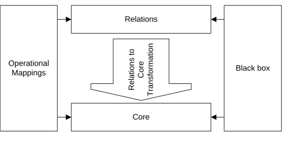
Operational Mappings is an imperative language that extends both Relations and Core. It provides control flow elements and a textual concrete syntax.
Relations
Figure 7 shows the layered structure of the three QVT languages. Operational Mappings is based on both Relations and Core, Relations can be transformed to Core. The black box in the figure is a mechanism to invoke transformations specified in other languages. For instance, a complex algorithm can be specified in a general purpose programming language that has a MOF binding.
In general, QVT can only be used for model to model transformations. Model to text transformations are not included in the specification.
1 --generate an overview page for this node (using the nodename)
2 mapping createOverviewPage( in element : diagram::Node) : applicationmodel::Page { 3 name := 'Overview of '+element.name+'s';
4 }
Code section 2: A sample of QVT Operational Mappings
Code section 2 shows a mapping operation in QVT Operational Mappings. A mapping operation describes how an element from the source model is mapped to an element from the target model. In this example a Node is mapped to a Page and the operation determines how the name of the node is mapped to the name of the page.
2.11
CONCLUSION
Chapter 3
3
SOFTWARE DEVELOPMENT PROCESSES
In this chapter we will describe the Rational Unified Process as an example of an iterative software development process. As we are interested in the problems that occur when MDA is applied with an iterative development process we need to have a common understanding of such a process. In our case study we will apply the Rational Unified Process because it is currently a de facto standard
(Kruchten, 2000).
3.1
SOFTWARE LIFE CYCLE
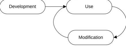
One of the most fundamental concepts in software engineering is the software life cycle (Glenn Brookshear, 2000). Figure 8 shows the software life cycle. This figure illustrates how the software cycles trough its life from being produced, used and modified. Like other manufactured products software needs modification once the product is in use. In contrast with other products, part of the software do not wear out. Software requires changes because the it contains errors, the environment changes or the demands of the users change.
Development Use
Modification
Figure 8: Software life cycle
3.2
WATERFALL MODEL
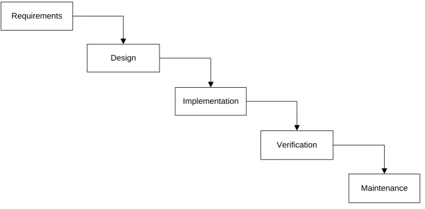
The software development process can have many forms. The ordering in which different activities are executed determine what type of process we have. The traditional waterfall model has six phases of development. Only if a phase is completed one may start working on the next phase. The model was first described by (Royce, 1987).
Requirements
Design
Implementation
Verification
Maintenance
Figure 9: Simplified schema of the waterfall model
The above figure (Figure 9) illustrates why it is called the waterfall model. First the requirements for a system are gathered and documented. Once this is done the requirements are fixed and the next step can be done: the design. Once the design of the system is completely finished one can start implementing it. After the implementation phase the test phase starts. Problems detected in this phase can be fixed and once the system is considered finished the maintenance phase starts.
This software development is considered a risky model because it is impossible to go back to an earlier phase. Once the system is implemented completely testing may begin. If major problems are detected in this phase, maybe design flaws, the whole system is already build. Changing the design at that stage of development is very expensive (Royce, 1987)
3.3
ITERATIVE MODEL
The iterative software development model is a model that was developed as a response to the harmful waterfall models (Kruchten, The Rational Unified Process: An Introduction, 2000). One of the problems of the waterfall model is that testing at the end of the development cycle may reveal problems that could have been solved in earlier stages of the project.
Requirements Design Implementation Verification
Next iteration
finished start
Figure 10:Schema of the Iterative model
There is a difference between incremental software development and iterative development. Both models divide the project in smaller pieces of work but in an incremental model the software system can only be extended in each iteration. In an iterative development model it is possible to build a piece in the first iteration and discard the work in the second iteration.
3.4
RATIONAL UNIFIED PROCESS
The Rational Unified Process (RUP) is an iterative software development process. The goal of RUP is to ensure the production of high quality software that meets the needs of its end users, on schedule and within budget. RUP provides a very systematic approach that defines roles and tasks for the organization of the project. RUP has been used for both small and large teams and long and short projects (Kruchten, The Rational Unified Process: An Introduction, 2000) (Rational Corporation, 1998).
3.4.1
BACKGROUND
The Rational Unified Process has a long history and was originally developed by Rational Corporation in the 1980’s and 1990’s. In 1995 Rational Corporation bought a Swedish company called Objectory AB. Their process, called Objectory process is combined with the knowledge of Rational at that time and Rational releases the Rational Objectory Process (ROP) in 1996. In 1998 it is renamed Rational Unified Process. The architect of RUP was Philippe Kruchten. In 2003 IBM acquired Rational and became the division IBM Rational (Amber, 2007).
The authors of RUP found that many of the software projects in the 80’s and 90’s were failing. They tried to find the main cause for the problems and tried to diagnose what went wrong. They diagnosed different characteristics of software projects and came up with a number of causes for software
Undetected inconsistencies in requirements, designs, and implementations Insufficient testing
Subjective assessment of project status Failure to attack risks
Uncontrolled change propagation Insufficient automation
used in RUP because it is observed that these are commonly used in the industry by successful organizations. RUP focuses on the following six best practices (Rational Corporation, 1998):
Develop software iteratively: The software systems that are developed today are complex systems. It is no longer possible to sequentially design, implement and test these systems in the end. In an iterative development process, understanding of the system is developed in small steps of refinement called iterations. In RUP, each of the iterations delivers a working product. The iterative nature of the project helps project management to identify and mitigate risks in early stages of the project. Because each iteration ends with a working product, it is also easier for customers to get involved in the project and to correct misunderstandings in early stages of the project.
Manage requirements: RUP describes precisely how to elicit, organize and document required functionality and constraints. RUP describes functionality in terms of use-cases and scenario’s. This will help communication with the business and is considered a good practice to capture functional requirements.
Use component-based architectures: In the early phases of development, RUP focuses on developing a baseline architecture that provides a solid base to develop the entire system. RUP helps designers to create a flexible, reusable and easy to understand architecture. RUP also provides the means to document the architecture trough UML models.
Visually model software: An important aspect of RUP is the use of UML throughout the design of a system. It prescribes different views for different stakeholder documenting the structures of the system in diagrams. The UML standard was originally developed by Rational Corporation.
Verify software quality: Today’s ever increasing complex software systems play an important role in our everyday lives. Software quality is becoming an important aspect and RUP helps developer creating high quality software. Quality assessments are part of the process, in all activities and phases.
Control changes to software: Managing changes in the software is part of the process. RUP describes how changes must be controlled, checked and monitored. It provides guidelines on how to setup the environments for developers so they are only allowed to change their own code.
3.4.2
PHASES
Figure 11: Phases and iterations of RUP5
From a project management perspective, RUP consists of four sequential phases: the inception, elaboration, construction and transition phase. Each of these phases can contain multiple iterations as shown in Figure 11 and ends with a milestone (dashed line). At the end of a phase, there is an assessment to verify if the goals for that phase are met. If the evaluation shows all goals are met, the project is allowed to proceed with the next phase.
Inception: The project starts with the inception phase. The goal for this phase is to reach agreement among different stakeholders of the project. Before the project can start, some business risks should be addressed and the initial requirements should be known. The focus of this phase is finding out if the project is worth taking the risk and whether the project is feasible. The assessment at the end of this phase is to evaluate if the project can continue.
Elaboration: In the elaboration phase, the baseline architecture of the system must be built. This baseline will be used in the next phase to build the major part of the system. In this phase, an executable system will be built that contains the most important requirements and shows the viability of the architecture. The exercise of building this baseline architecture should identify the risks in the project.
Construction: During the construction phase the remaining part of the requirements are clarified and the baselined architecture is completed. The construction phase can be considered the manufacturing phase of the system. In the previous phases, the focus was the intellectual challenge, but in the construction phase the focus is managing resources and developing the major part of the system. At the end of the construction phase, the system is tested and is ready for acceptance testing.
system at this stage. This phase also contains configuration, installation and addressing usability issues. The assessment at the end of the phase is to decide if the system meets the objectives.
3.4.3
ROLES
In RUP there are 24 roles defined. There are two or more roles for each of the nine disciplines. Essentially, there is division between two types of roles. A role for a person that focuses on breadth and a role for a person that focuses on depth. The following roles are defined:
Business Process Architect: Discovers all business use-cases. Business Designer: Details a single set of business use-cases. System Analyst: Discovers all requirement use-cases. Requirements Specifier: Details a single set of requirements. Software Architect: Decides on technologies for the whole solution. Designer: Details the analysis and design of a single set of use-cases.
Integrator: Owns the build plan that shows what classes will integrate with one another. Implementer: Codes a single set of classes or a single set of class operations
Test Manager: Ensures that testing is complete and conducted for the right motivators. Test Analyst: Selects what to test based on the motivators.
Test Designer: Decides what tests should be automated and creates automations. Test Designer: Implements automated portions of the test design for the iteration. Tester: Runs a specific test.
Deployment Manager: Oversees deployment for all deployment units.
Tech writer, course developer, graphic artist: Create detailed materials to ensure successful deployment.
Project Manager: Creates a business case and a course-grained plan. Project Manager: Plans, tracks and manages risk for a single iteration. Process Engineer: Owns the process for the project.
Tool Specialist: Creates guidelines for using a specific tool.
Configuration Manager: Sets up the CM environment, policies and plan. Change Control Manager: Establishes a change control process
Configuration Manager: Creates a deployment unit, reports on configuration status, etc. Change Control Manager: Reviews and manages change requests.
3.4.4
RUP AND MDA
The application of MDA in a RUP project requires some changes in the software development process. New artifacts need to be introduced to the development process as RUP does not consider model transformations. Also, new roles can be introduced. An IBM article describes a number of changes in RUP, based on their experience with MDA and RUP.
According to (Brown & Conallen, 2005), one new role can be added to the development process. This new role is a specialization of the architect called the MDA architect. This person is responsible for designing the main meta-models, transformations and mapping documents.
transformations instead of writing code based on UML diagrams provided by the designers. The focus of designers is more in the business level then in technical level.
The article also describes some changes in the phases. The phase that changes most is the elaboration phase. In this phase, a large part of the MDA work needs to be done. The meta-models and basic transformations need to built to see if the approach is feasible. Work in the construction phase will shift to modeling and writing transformations instead of working with source code.
One of the best practices of RUP is to use a component based architecture. MDA augments the use of component based architectures by providing the means to automate a large part of the work on integrating the components.
3.5
OPEN UNIFIED PROCESS
This section describes the Open Unified Process (Balduino, 2007) and the Model Driven Development plug-in for this development process. The Open Unified Process (OpenUP) is an open source version of the Rational Unified Process. It has been developed as a part of the Eclipse Process Framework project. This project provides an open and extensible framework for developing and maintaining processes and tools.
3.5.1
DESCRIPTION
The OpenUP is a family of software development processes built on top of the OpenUP/Basic. The OpenUP/Basic is an iterative software development process that claims to be minimal, extensible and complete. With a minimal process, the developers mean a process that contains only fundamental content. Extensible means a process that can be used as a basis for other processes and complete indicates that the process covers all aspects of software development (Lyons, 2007).
The OpenUP/Basic is a development processes that follows an agile philosophy (Ambler, 2007). The development process focuses on collaboration and delivering working products rather than focusing on formality.
OpenUP focuses on the following four principles:
Collaborate to align interests and share understanding. Balance competing priorities to maximize stakeholder value.
Focus on the architecture early to minimize risks and organize development. Evolve to continuously obtain feedback and improve
Agile software development is an incremental and iterative approach which is performed in a highly collaborative way using self organizing teams with low overhead and the focus on high quality software, delivered on time and cost effective (Ambler, 2007). Agile software development is based on the Agile manifesto (Beck, et al., 2001). This manifesto describes the core values of the agile philosophy: Individuals and interactions over processes and tools, working software over comprehensive documentation, customer collaboration over contract negotiation, responding to change over following a plan.
characteristic of a light weight RUP; it is based on use-cases, iterations, risk management and an architectural centered approach.
OpenUP addresses the organization of work at three levels: personal, team and stakeholder levels. At the personal level, the work is organized in micro increments. Small units of work that span several hours or days. Team members share their progress at all three levels to monitor project progress.
3.5.2
PHASES
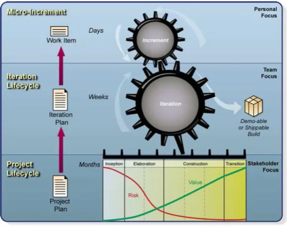
The division in phases and iterations reflects the origins of OpenUP. The project contains the same four phases as RUP: inception, elaboration, construction and transition. Each phase can contain multiple iterations and each iteration contains micro increments. At the end of each iteration, the project team delivers a testable demo or shippable build. This helps the team focus on it goals and offers the stakeholders a predictable lifecycle.
Figure 12: OpenUP Structure (Balduino, 2007)
3.5.3
ROLES
In the OpenUP, the following roles are defined for team members (Balduino, 2007):
Stakeholder: A person or interest group whose needs must be satisfied by the project. Can be represented by anyone who is or will be materially influenced by the project.
Analyst: Represents customer and end-user concerns by gathering input from the stakeholders to understand the problem to be solved.
Architect: Responsible for designing the software architecture and for making key technical decisions.
Tester: Responsible for all the core testing activities. This includes identifying, implementing, and conducting tests as well as logging and analyzing the results.
Project manager: Leads the planning of the project and handles communication with stakeholders. Keeps the team focused on the project goals.
3.5.4
OPENUP AND MDA
The OpenUP/Basic has been developed to form the basis for other development processes. In 2006, the development of a Model Driven Plug-in for the OpenUP started based on OpenUP/Basic. This plug-in provides new process elements that are specific for a model driven development project.
The OpenUP/MDD plug-in redefines a number of roles and provides a number of new roles that extend the existing roles of OpenUP:
Analyst: The role of the analyst changes. The analyst should be aware of the fact that problems should be analyzed at model level.
Application designer: Designs the transformations from PSM to code.
Business expert: Designs profiles for specific business domains
Domain expert: Has a detailed understanding of certain domains.
Language engineer: Is an expert in modeling languages.
Platform expert: Is responsible for defining platforms. These platform specifications can be used to create the models at PSM level.
Requirements specifier: Specifies the requirements.
Test designers: The person responsible for defining the test approach.
Transformation specifier: Responsible for the specification of the PIM to PSM model transformations.
The OpenUP/MDD plug-in is created as part of the Eclipse project and can be found here: (Eclipse Process Framework OpenUP/MDD, 2006).
3.6
CUSTOMIZATION OF RUP AND OPENUP
Both RUP and OpenUP are complete software development processes that contain detailed descriptions of each step in the process. However, not every company uses exactly the same process and therefore these processes must be adaptable to their environment.
software development processes. The EPF provides the EPF Composer as a tool to define and adapt software development processes (Eclipse Process Framework Project).
3.7
MAINTENANCE AND EVOLUTION
Two very important and related aspects of software engineering are software maintenance and evolution. After the software has been delivered (See Figure 8) and the software is in use the maintenance phase begins. Software maintenance is defined as:
“The modification of a software product after delivery to correct faults, to improve performance or other attributes, or to adapt the product to a modified environment.” (Bennett & Rajlich, 2000)
Maintenance can be applied for a number of reasons, but in the literature one often finds the following types of maintenance activities (IEEE, 1990):
Adaptive maintenance: changes in the software environment Perfective: new user requirements
Corrective maintenance: fixing errors Preventive: prevent problems in the future
These types of maintenance are defined based on the nature of the change. An adaptive change is a change in the environment of the system. Therefore, the system must be adapted to fit in the changed environment. An example of such a change is an update of an underlying system. If a software product is depending on another system and this underlying system changes, the software must be adapted. Perfective changes are modifications on the software because the requirements of the users change. An example of such a change is a helpdesk system for an internet provider and the internet provider starts delivering new services. The software system should then be adapted to support the helpdesk with these new services. Corrective maintenance activities are related to errors in the system. Every software system contains errors and these should be fixed if they are detected and pose a problem for the users. Preventive maintenance activities focus on preventing future problems. An example of preventive maintenance is the addition of a stronger encryption algorithm in a banking system. The current encryption algorithm may be strong enough, but once an algorithm is broken it is too late to repair the system.
The term software evolution is used to indicate the phase of the software after it has been developed. Once the system is developed it starts evolving. Any successful software product will be used and maintained. During these cycles of maintenance the software evolves.
More detailed descriptions of maintenance activities and software evolution can be found in (Chapin et al., 2000). A more in depth characterization o