Compact CPW-Fed Multiband Antenna for
TD-LTE/WLAN/WiMAX Applications
Gui Liu*, Mengli Fang, Ruixing Zhi, Jin Bai, and Zhe Zeng
Abstract—A compact coplanar waveguide fed multiband antenna is proposed and investigated. The proposed antenna consists of a rectangular radiating patch and dual meander strips with a defected ground plane. The size of the fabricated prototype is 28.3×24×1.59 mm3. The proposed antenna radiates at three different resonant modes, which cover 2.29–2.63 GHz, 3.26–3.96 GHz, and 4.97– 6.10 GHz. The proposed antenna can be used for TD-LTE 2300/2500 (2.305–2.4 GHz), WLAN (2.4– 2.4835 GHz and 5.15–5.875 GHz) and WiMAX (2.3–2.4 GHz and 3.3–3.7 GHz) applications. The proposed antenna exhibits an omnidirectional radiation pattern in the H-plane and a dipole-like radiation pattern in the E-plane. The measured peak gains are 2.64/4.48/6.08 dBi at 2.4/3.5/5.5 GHz operating frequency bands, respectively.
1. INTRODUCTION
With strong demands on wireless communication systems, more and more mobile devices can accommodate various wireless services such as the Time Division-Long Term Evolution (TD-LTE), Wireless Local Area Network (WLAN) and Worldwide Interoperability for Microwave Access (WiMAX). In the pursuit of low cost, low volume and multiband operations, the design of multiband antennas has attracted a lot of interest in academia and industries since a multiband antenna can simultaneously operate at different frequency bands. Multiband antennas can reduce the number of antennas and remove the bandpass filters used in a multiband system, which is critical for mobile devices to minimize the overall volume, fit the severe physical space constraints, and save the cost.
Until now, various techniques have been proposed to design multiband antennas [1–9]. One of the design techniques to achieve multiband operation is to use slots to modify the radiator or ground plane. In [1], tri-band operation of the proposed antenna is obtained by a rectangular slot, a trapezoid slot and strips embedded in the rectangular slot on the ground plane. In [2], multiband characteristics can be achieved by tuning the locations and sizes of a modified rectangular slot, and a Y-shaped monopole radiator with a meandering split-ring slot. By carefully selecting the positions and lengths of two bent slots, a good dual-stopband rejection characteristic of the proposed antenna can be obtained so that three operating bands covering 2.14–2.85, 3.29–4.08, and 5.02–6.09 GHz can be obtained [3].
Other techniques of realizing multiband resonance are to use strips to create different current paths and thus multiple resonant frequencies. In [4], three radiating elements together with an additional strip are utilized to produce three distinct frequencies. A Y-shape-like strip in a circular ring of the proposed antenna can excite two resonant modes, and a defected ground plane can produce the third resonance frequency [5]. In [6], the proposed antenna including a defected ground structure (DGS) with dual inverted L-shaped strips and a cross-shaped stripline can achieve three resonances and bandwidth
Received 22 Octobers 2016, Accepted 26 November 2016, Scheduled 18 December 2016
* Corresponding author: Gui Liu ([email protected]).
The geometry of the proposed multiband antenna is illustrated in Figure 1. The antenna was fabricated on a 1.59 mm thick FR-4 substrate with a permittivity of 4.4 and loss tangent of 0.02. The antenna is fed with a 50-Ω coplanar waveguide, and the overall dimension is 28.3×24×1.59 mm3. The ground plane is chopped by two rectangles and triangles. The width and length of the rectangles and triangles, and the distance between the ground plane and radiator patch are optimized to achieve good impedance matching performance over the desired frequency bands. The total length of the meander lines is about 27.5 mm, which is close to a quarter guided wavelength of the lower resonance frequency (2.45 GHz). The guided wavelength is given by
λg= c εr+ 1
2 f
(1)
where c is the speed of light, εr the relative permittivity of the substrate, and f the desired resonant frequency.
Figure 1. Geometry of the proposed antenna.
3. SIMULATION AND EXPERIMENTAL RESULTS
The proposed antenna was simulated by a 3D high performance full-wave electromagnetic (EM) field simulator HFSS. The reflection coefficients at different values of L3 are illustrated in Figure 2. The
resonance frequencies at three frequency bands shift towards lower frequency band as the value of L3
increases. The optimized value of L3 is 7.5 mm, and the frequency band ranges from 2.09 to 2.51 GHz,
accordingly.
Figure 3 shows the simulated refection coefficients for a parameter study of the length (L6) of the
patch. It can be seen that the middle frequency band can be effectively tuned byL6 while keeping the
Figure 2. Simulated reflection coefficients of the proposed antenna with different values ofL3.
Figure 3. Simulated reflection coefficients of the proposed antenna with different values ofL6.
As depicted in Figure 4, variation of the value ofL7 significantly affects the matching characteristic
of the middle and higher frequency bands. As the value of L7 increases, the frequency bands shift
towards the lower frequencies. The optimal value of L7 is 2 mm.
The effect of the defected ground plane on the impedance matching characteristics is depicted in Figure 5. In Figure 5, the resonance frequency and bandwidth of the higher frequency bands can be effectively tuned by the value of W7.
Figure 4. Simulated reflection coefficients of the proposed antenna with different values ofL7.
Figure 5. Simulated reflection coefficients of the proposed antenna with different values ofW7.
The operation principle of the proposed antenna is examined by analyzing the surface current distribution at three different resonant frequencies. As shown in Figure 6(a), the current mainly distributes over the meander lines at 2.4 GHz. A relative strong current is concentrated along the meander lines and the connection strip between the rectangular radiator and meander lines at 3.5 GHz are presented in Figure 6(b). As for the higher frequency (5.5 GHz), the current mainly concentrates on the slot between the signal line and the coplanar ground planes.
Figure 7 shows the photograph of the fabricated prototype. The final geometric parameters are W1 = 1.5 mm, W2 = 7 mm, W3 = 3.5 mm, W4 = 1.4 mm, W5 = 1.94 mm, W6 = 3 mm, W7 = 4 mm,
W8= 4 mm,W9 = 2.4 mm, W10= 10.5 mm,W11= 0.3 mm, W12 = 24 mm, L1 = 28.3 mm, L2 = 9 mm,
L3 = 7.5 mm,L4 = 4 mm,L5 = 4 mm,L6= 5.3 mm,L7= 2 mm, L8= 1.93 mm, and L9= 2.84 mm.
(a) (b)
Figure 7. Photograph of the fabricated prototype (a) top view and (b) bottom view.
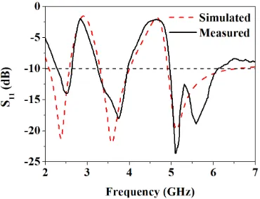
Figure 8. Simulated and measured reflection coefficients of the fabricated prototype.
(a)
(b)
(c)
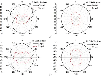
Figure 9. Measured radiation patterns of the fabricated prototype at (a) 2.4 GHzE-plane andH-plane (b) 3.5 GHz E-plane andH-plane and (c) 5.5 GHzE-plane andH-plane.
(c)
(a) (b)
Figure 10. Measured peak gain at (a) 2.4 (b) 3.5 and (c) 5.5 GHz of the fabricated prototype.
and measured results can be observed which is mainly due to the manufacturing tolerance and the mismatching between the SMA connector and the antenna feeder.
ACKNOWLEDGMENT
This work was supported by the National Natural Science Foundation of China under Grant No. 61340049 and No. 61671330, Science and Technology Program in Public Interest of Wenzhou Science and Technology Bureau under Grant No. G20140056, and Zhejiang Provincial Natural Science Foundation of China under Grant No. LY12F04002.
REFERENCES
1. Dang, L., Z. Lei, Y. Xie, G. Ning, and J. Fan, “A compact microstrip slot triple-band antenna for WLAN/WiMAX applications,” IEEE Antennas Wireless Propag. Lett., Vol. 9, 1178–1181, 2010. 2. Liu, P., Y. Zou, B. Xie, X. Liu, and B. Sun, “ Compact CPW-fed tri-band printed antenna with
meandering split-ring slot for WLAN/WiMAX applications,” IEEE Antennas Wireless Propag.
Lett., Vol. 11, 1242–1244, 2012.
3. Liu, H., C. Ku, and C. Yang, “Novel CPW-fed planar monopole antenna for WiMAX/WLAN applications,” IEEE Antennas Wireless Propag. Lett., Vol. 9, 240–243, 2010.
4. Mehdipour, A., A. Sebak, C. Trueman, and T. Denidni, “Compact multiband planar antenna for 2.4/3.5/5.2/5.8-GHz wireless applications,” IEEE Antennas Wireless Propag. Lett., Vol. 11, 144– 147, 2012.
5. Pei, J., A. Wang, S. Gao, and W. Leng, “Miniaturized triple-band antenna with a defected ground plane for WLAN/WiMAX applications,”IEEE Antennas Wireless Propag. Lett., Vol. 10, 298–301, 2011.
6. Liu, W., C. Wu, and Y. Dai, “Design of triple-frequency microstrip-fed monopole antenna using defected ground structure,”IEEE Trans. Antennas Propag., Vol. 59, No. 7, 2457–2463, 2011. 7. Xu, P., Z.-H. Yan, and C. Wang, “Multi-band modified fork-shaped monopole antenna with dual
L-shaped parasitic plane,” Electron. Lett., Vol. 47, No. 6, 364–365, 2011.
8. Herraiz-Mart´ınez, F., G. Zamora, F. Paredes, F. Mart´ın, and J. Bonache, “Multiband printed monopole antennas loaded with OCSRRs for PANs and WLANs,”IEEE Antennas Wireless Propag.
Lett., Vol. 10, 1528–1531, 2012.
9. Li, D. and J.-F. Mao, “Multiband multimode arched bow-shaped fractal helix antenna,” Progress