Scholarship@Western
Scholarship@Western
Electronic Thesis and Dissertation Repository
1-19-2016 12:00 AM
Application of Treated Oil Sands Drill Cuttings Waste in Micropiles
Application of Treated Oil Sands Drill Cuttings Waste in Micropiles
Construction
Construction
Moustafa Ahmed Raafat Mohamed Aboutabikh
The University of Western Ontario
Supervisor
M. Hesham El Naggar
The University of Western Ontario
Graduate Program in Civil and Environmental Engineering
A thesis submitted in partial fulfillment of the requirements for the degree in Master of Science © Moustafa Ahmed Raafat Mohamed Aboutabikh 2016
Follow this and additional works at: https://ir.lib.uwo.ca/etd
Part of the Civil Engineering Commons, Environmental Engineering Commons, Geotechnical Engineering Commons, Mining Engineering Commons, Other Civil and Environmental Engineering Commons, Other Materials Science and Engineering Commons, Petroleum Engineering Commons,
Structural Engineering Commons, and the Structural Materials Commons
Recommended Citation Recommended Citation
Aboutabikh, Moustafa Ahmed Raafat Mohamed, "Application of Treated Oil Sands Drill Cuttings Waste in Micropiles Construction" (2016). Electronic Thesis and Dissertation Repository. 3472.
https://ir.lib.uwo.ca/etd/3472
This Dissertation/Thesis is brought to you for free and open access by Scholarship@Western. It has been accepted for inclusion in Electronic Thesis and Dissertation Repository by an authorized administrator of
ii
A micropile is constructed by drilling a hole, placing a steel reinforcing element, grouting
it using neat cement. However, cement production consumes energy and generates carbon
dioxide. Implementing waste materials in construction applications represents a sustainable
solution for many waste management problems. On the other hand, oil sands drill cuttings
waste represents one of the most difficult challenges for the oil sands mining sector.
Reducing the amount of oil sands drill cutting waste sent to landfill offers one of the best
solutions for waste management. This thesis presents an innovative solution for application
of treated oil sands waste (TOSW) in grout mixtures used for micropiles construction. In
this study, the physical, chemical and mineralogical characteristics of the treated oil sands
drill cuttings waste were investigated. Fresh and hardened properties for micropiles grouts
incorporating the treated solid drill cuttings waste were evaluated. Moreover, the effects of
employing these grout mixtures on micropiles cross-section, surface interface properties
and axial behaviour were investigated. The results showed that incorporating up to 20% of
the treated solid drill cuttings waste as a partially replacement of cement will not adversely
affect the properties of the grout. On the other hand, leaching tests evidenced the reduction
in the release of heavy metals from the tested mixtures compared to that of the raw waste
indicating successful stabilization/solidification of such waste in the grout. In addition, it
was noticed an enhancement in the grout body diameter for micropiles installed using the
developed grout, while maintaining the micropile surface properties. Moreover, micropiles
installed using grout incorporating a high percentage of the TOSW (up to 30%) exhibited
the same axial behaviour as that of micropile installed using conventional grout. Therefore,
incorporating TOSW in micropile applications has high potential for producing cost
efficient micropiles along with providing a green oil sands waste management solution.
iii
Co-Authorship Statement
This thesis has been prepared in accordance with the regulation of integrated-article format
stipulated by the Faculty of Graduate Studies at The University of Western Ontario.
Substantial parts of this thesis were either published in or submitted for publication to
peer-reviewed technical journals and an international conference. All experimental work, data
analysis, modeling process and writing of initial versions of all publications listed below
were carried out by the candidate himself. The contribution of his research advisor and any
other co-author, if applicable, consisted of either providing advice, and/or helping in the
development of the final versions of publications:
1-Moustafa Aboutabikh, Ahmed M. Soliman and M. Hesham El Naggar (2015) “Properties of Cementitious Materials Incorporating Treated Oil Sands Drill Cuttings
Waste,” Construction and Building Materials. Accepted.
2-Moustafa Aboutabikh, Ahmed M. Soliman and M. Hesham El Naggar (2015) “Performance of Hollow Bar Micropiles Using Sustainable Grout,” The ASCE Journal
and Geoenvironmental Engineering. Submitted.
3- Moustafa Aboutabikh, Ahmed M. Soliman and M. Hesham El Naggar (2015) “Effect of Treated Oil Sands Drill Cuttings Waste on Micropiles Grout Properties,” In Proceeding of the 68th Canadian Geotechnical Conference, Quebec City, Quebec,
Canada. Published.
4-Moustafa Aboutabikh, Ahmed M. Soliman and M. Hesham El Naggar (2015) “Application of Different Industrial Waste Materials in Geotechnical Applications,” Proceedings of the Annual Conference of the Canadian Society for Civil Engineering,
London, Ontario, Canada. Submitted.
iv
To:
My Father Ahmed
My Mother Wafaa
My Sister Marwa, My Brother Salah, Liala and Noura
My Sister Farah
My Beloved Fiancée Hadil
My Brother DR. Ahmed Soliman
v
Firstly, I would like to express my sincere gratitude to my supervisor Prof. Hesham El
Naggar for the continuous support during my Master study and related research, for his
patience, motivation, and immense knowledge. His guidance helped me in all the time of
research and writing of this thesis. I could not have imagined having a better advisor and
mentor for my Master study.
Special appreciation to Dr. Ahmed Soliman for his continuous support and help during my
work and sharing his valuable experience with me.
My sincere thanks also goes to my dearest friend Mahmoud Kassem who was always by
my side, helping during my research period. I want also to express my very deep thanks to
all my friends who helped me during the construction of Micropiles, specially Ahmed
Reda, Ahmed Al Shaer, Mohamed Gebril and Mohamed Mansour. I am also grateful to my
friends in and outside the university who always supported me in overcoming many
difficulties during my study. Furthermore, I want to thank Mr. Wilber Logan, Western
Engineering labs supervisor, for his suggestions and assisting during my laboratory testing.
A special thanks to my family. Words cannot express how grateful I am to my parents,
sisters Marwa and Farah, and my brother Salah for all of the sacrifices that they’ve made
on my behalf. Your prayer for me was what sustained me thus far. At the end I would like
express appreciation to lovely fiancée Hadil for supporting me spiritually throughout my
vi
Abstract………...ii
Co-Authorship Statement………...iii
Acknowledgments………..v
Table of Contents……….. vi
List of Tables………..……....x
List of Figures………....xi
List of Symbols……….xiv
CHAPTER ONE
INTRODUCTION
1.1. OVERVIEW ...11.1.1. Micropiles Background ...3
1.1.2. Oil Sands in Canada ...4
1.1.3. Oil Sands Wastes ...5
1.1.4. Treated Oil Sands Waste ...6
1.2. RESEARCH OBJECTIVES AND METHODOLOGY ...7
1.3. THESIS ORGANIZATION...10
1.4. REFERENCES ...12
CHAPTER TWO
LITERATURE REVIEW
2.1. INTRODUCTION ...152.2. MICROPILES CLASSIFICATION ...17
2.2.1. Design Classification of Micropiles...18
vii
2.5. DESIGN PHILOSOPHY ...26
2.5.1. Structural Design of Micropiles ...26
2.5.2 Geotechnical Design Capacity of Micropiles ...27
2.6. REVIEW OF PREVIOUS STUDIES ...29
2.6.1 Case Studies for Micropiles ...29
2.6.2 Case Studies for Hollow Bar Micropiles ...30
2.6.3. Analytical and Theoretical Analyses ...32
2.6.4. Numerical Analysis ...32
2.7. IMPLEMENTATION OF INDUSTRIAL WASTE IN CONSTRUCTIONAL APPLICATIONS ...33
2.7.1. Case Studies for Reusing of Waste Materials in Constructional Applications ...34
2.7.2. Treated Oil Sands Drill Cuttings Waste...38
2.8. SUMMARY ...43
2.9. REFERENCES ...44
CHAPTER THREE
PROPERTIES OF CEMENTITIOUS MATERIAL INCORPORATING
TREATED OIL SANDS DRILL CUTTINGS WASTE
3.1. INTRODUCTION ...523.2. EXPERIMENTAL PROGRAM ...54
3.2.1. Materials and Mixtures Proportions...54
3.2.2. Tests and Specimens Preparation...57
3.3. RESULTS AND DISCUSSION ...58
3.3.1. Water of Consistency ...58
3.3.2. Heat of Hydration ...59
viii
3.3.5. Leaching ...70
3.4. CONCLUSIONS...72
3.5. REFERENCES ...75
CHAPTER FOUR
PERFORMANCE OF HOLLOW BAR MICROPILES USING
SUSTAINABLE GROUT
4.1. INTRODUCTION ...814.2. EXPERIMENTAL PROGRAM ...83
4.2.1. Materials and Mixtures Proportions...83
4.2.2. Testing Procedure and Methodology ...84
4.2.2.1. Grout Testing and Evaluation ...84
4.2.2.2. Hollow Bar Micropile Installation ...85
4.2.2.3. Hollow Bar Micropile Axial Compression Loading Test ...89
4.2.2.4. Surface Profile Evaluation of Hollow Bar Micropile ...91
4.2.2.4.1. Roughness Evaluation ...91
4.2.2.4.2. Interface Friction Angle ...92
4.3 RESULTS AND DISCUSSIONS ...93
4.3.1. Grout Properties ...93
4.3.2. Micropile Profile ...95
4.3.2.1. Micropiles Interface Roughness ...98
4.3.2.2. Micropiles Interface Shear Strength ...103
4.3.3. Axial Behaviour of Hollow Bar Micropiles...105
4.3.3.1. Load Displacement Curves ...106
4.3.3.2. Load Transfer Mechanism ...110
4.4. CONCLUSIONS ...116
ix
CHAPTER FIVE
SUMMARY, CONCLUSIONS, AND RECOMMENDATIONS
5.1. SUMMARY ...123
5.2. CONCLUSIONS...124
5.2.1. Properties of Cementitious Material Incorporating Treated Oil sands Drill Cuttings Waste ...124
5.2.2. Performance of Hollow Bar Micropiles Using Sustainable Grout ...125
5.3. RECOMMENDATION FOR FUTURE RESEARCH ...126
x
LIST OF TABLES
Table 2.1: Grout-to-ground bond values ...28
Table 3.1: Chemical composition and physical properties of cementitious materials ...56
Table 3.2: Composition for tested mixtures ...57
Table 3.3: Slopes of heat flow curves during the acceleration periods for tested mixtures ...63
Table 3.4: Leaching test results of TOSW ...73
Table 4.1: Chemical composition and physical properties of cementitious materials ...84
Table 4.2: Concrete sand soil properties ...88
Table 4.3: Grout mixtures fresh and hardened properties ...94
Table 4.4: Pile interface roughness and shear strength properties ...98
xi
LIST OF FIGURES
Figure 2.1: Micropiles system components ...16
Figure 2.2: Typical Cross section for micropiles ...16
Figure 2.3: Different applications for micropiles ...18
Figure 2.4: CASE 1 micropiles ...19
Figure 2.5: CASE 2 micropiles ...20
Figure 2.6: Micropile classification system based on method of grouting ...22
Figure 2.7: Type E hollow bar micropile ...23
Figure 2.8: Solid bar micropile with casing and hollow bar micropile ...24
Figure 2.9: Hollow-bar micropile parts ...25
Figure 2.10: Alberta’s oil sands areas ...39
Figure 2.11: Characteristics of oil sands ...39
Figure 2.12: In-situ mining ...40
Figure 2.13: Open pit mining ...41
Figure 2.14: Thermo-mechanical Cuttings Cleaner ...42
Figure 3.1: SEM image and EDX for TOSW ...55
Figure 3.2: Particle size distribution using Laser diffraction for OPC and TOSW ....56
Figure 3.3: Effect of TOSW replacement rate on cement paste water of consistency ...59
xii
Figure 3.6: DTG curves for cement pastes incorporating different percentages of
TOSW ...65
Figure 3.7: Compressive strength results for mixtures incorporating different percentages of TOSW ...66
Figure 3.8: Reduction in compressive strength due to TOSW incorporation at different ages ...67
Figure 3.9: Measured shrinkage for mixtures incorporating different percentages of TOSW ...69
Figure 3.10: Measured mass loss for mixtures incorporating different percentages of TOSW ...70
Figure 3.11: Pore size distribution for mixtures incorporating different percentages of TOSW ...72
Figure 4.1: Micropile a) R38-420 DYWI Hollow Bars and b) Carbide button cross cut drill bit (d = 90mm)……….… 86
Figure 4.2: Steel tank used in the installation of micropiles ...87
Figure 4.3: Guiding system to insure verticality of hollow bar micropiles ...87
Figure 4.4: Pressure cone used for injecting grout under pressure ...89
Figure 4.5: Illustration for a) axial Compressive testing setup and b) locations of strain gauges on the micropile ...90
Figure 4.6: Direct shear test a) slice sample and b) test configuration ...93
Figure 4.7: Changes in hollow bar micropile diameter over the length for a) 0%, b) 10%, c) 20%, and d) 30% TOSW ...96
Figure 4.8: Illustration for a) Cross-section for a tested micropile and b) Threaded bar grout bond surface profile ...97
Figure 4.9: Roughness profile of different hollow bar micropile sections ...99
Figure 4.10: Calculated interface angle using direct shear test results ...104
Figure 4.11: Load-displacement curves for micropiles a)MP0, b)MP10, c) MP20 and d)MP30 ...107
xiii
xiv
Ag Area of the grout
As Area of the steel pile
Ap Cross sectional area of micropile
dbar Hollow bar diameter
dbit Drill bit diameter
D Diameter of pile
Dr Relative density
E Young’s modulus
Eg Modulus of elasticity of grout
Ep Modulus of elasticity of pile
Es Moadulus of elasticity of steel
emax Maximum voids ratio
emin Minimum voids ratio
fa Axial applied stress
Fa Allowable axial stress
f’c Compressive strength of grout
fy Specific yield of steel
Gs Specific gravity
ID Inner diameter
L Pile length
xv
PT-Allowable Allowable structural axial tension load
Pult Ultimate capacity of micropiles in tension or compression
Ra Average roughness
Rt Total roughness
wc Water content
ε Total strain measurement
ϕ° Effective friction angle
CHAPTER ONE
INTRODUCTION
1.1. OVERVIEW
Micropiles are a small diameter drilled and grouted piles (less than 300 mm). The
construction of micropiles consists of drilling a borehole, placing a steel reinforcement and
placing or injecting grout in the borehole. The grout is placed by gravity, under pressure or
using both methods (post grouting). Micropiles are typically reinforced by a solid or hollow
steel bar. Micropiles can carry axial and lateral loads, which make them a possible
alternative for the conventional piling systems, which includes driven piles or drilled
shafts. Micropiles are mainly used for underpinning existing foundations, soil
reinforcement, seismic retrofitting and they can also be used as foundations for new
constructions.
Micropiles have several advantages including the possibility of installation in most
soil types and rocks. In addition, due to the small size of the installation equipment,
micropiles can be installed in limited head room causing minimal vibration, and
disturbance to adjacent structures.
Due to the new drilling and grouting techniques, high strength grout to ground bond
transfer between the reinforcement and the surrounding ground, forming a part of the
load-bearing cross section of the micropile, and acting as a protective layer for the steel
reinforcement from corrosion. The grout to ground bond strength achieved is mainly
dependant on the soil type and the grouting method. Due to the small cross-section of
micropiles, the end bearing contribution in the capacity of micropiles is generally neglected
(FHWI NHI, 2005).
Grout mixtures usually consist of cement and water; and in certain cases additives
are added in order to enhance the grout properties. However, cement industry is a major
contributor to the CO2 emissions around the world. On the other hand, one of the great
challenges now for civil and environmental engineers is to divert industrial waste towards
useful construction purposes. In the last few years, oil sands industry has become one of
the major waste sources in western Canada. Oil sands drilling cuttings are considered a
difficult challenge for the oil sands mining sector. Different treatment methods for the oil
sands waste were applied in order to convert these wastes to a product that can be safely
disposed or can have the potential to be recycled in other applications. One of the recent
technologies for oil sands waste treatment (so called Thermo-mechanical Cutting Cleaner
(TCC)) was proposed. In the TCC, the waste is heated to a temperature high enough to
evaporate oil and water. The oil and water are brought back to a liquid phase in separate
condensers. The remaining by-product of TOSW is very fine quartzes powder with an
acceptable disposal limit of hydrocarbons (less than 1%), and having the potential to be
used as filler material in constructional applications (Haliburton thermomechanical
cuttings cleaner, 2014, Thermtech AS, 2010 ). Many researches have reported the
can affect the physical and chemical properties of cementitious materials. It also should
not increase the water demand when used in cementitious materials.
Therefore, this study presents an innovative solution for treated oil sand wastes
(TOSW) disposal in micropiles grout. This would expand TOSW recycling in several
construction applications, leading to a better and more sustainable environment.
1.1.1. Micropiles Background
Micropiles were presented first in Italy in 1952, when Dr. Fernando Lizzi used them in the
application of underpinning historic buildings damaged during World War II (Bruce,
1988). The first generation of micropiles were small diameter (less than 100 mm), drilled,
cast-in-place, lightly reinforced, grouted piles that are designed to carry loads less than 100
kN. Since then, micropiles construction has been expanding rapidly all over the world, and
micropiles were upgraded to larger diameters (up to 300 mm).
The second generation of micropiles was presented in the 1970s, which were
installed by using either an open or cased hole drilling method with a central reinforcement
bar filled with grout. This generation was known with different names including; mini
piles, needle piles, and GEWI-Pile. The name of micropiles was approved by the Federal
Highway Administration (FHWA) in 1993, and was used as the common name for this
type of piles.
A third generation was presented by Ernst Ischebeck in 1983; and named the Titan
Injection Bore (IBO) micropile (CON-TECH SYSTEM, 2011). This type is a continuously
to proceed simultaneously without the need for a casing. To drill this type of micropiles, a
sacrificial bit containing openings that allow for pressure grouting of the surrounding soil
is threaded onto the end of the hollow bar. This system has been known as “self-drilling
anchoring” because the installation is done in a single operation as the hollow bar serves
as both the drill string and the grouted anchor (William Form–Ground Anchor system 2010).
The use of hollow bars for micropiles construction has increased over the past 10
years. Hollow bars became preferred by many contractors because it is characterized by
easy and fast installation with a high degree of ground improvement.
1.1.2.
Oil Sands in CanadaThe exploration of oil sands in Canada started in the 1940s when the Alberta government
partnered with a company called Oil Sands Limited to build a pilot oil sands extraction
plant at Bitumount (Woynillowicz, et al., 2005). However, the construction of the plant
and the extraction costs of oil were doubled in the following years which made Oil Sands
Limited to pull out. Commercial development started in 1967 when the Great Canadian Oil
Sands Company commissioned the first open pit surface mine. Later, Syncrude started its
oil sands extraction in 1978 carrying the oil from their plant to Edmonton through a pipeline
system owned by Syncrude (Ritts, 2010). However, for several years the oil sands industry
faced numerous challenges such as breakdowns, freeze ups, fires and high production costs.
Several technologies were invented in order to enhance oil sands production and
reduce its extraction costs. By 1986, the cost of producing synthetic crude oil was reduced
considered risky and unprofitable. In 1995, the government of Canada introduced new
strategy to double or triple the production of oil sands by 2020, reaching between 800,000
and 1.2 million barrels per day (National Task Force, 1995). By 2012, Alberta was able to
produce 1.9 million barrels per day of crude bitumen, a huge increase to the anticipated
amount and timeline introduced by the government (Alberta Oil Sands Industry, 2013).
The scale of this new development exceeded the expectations greatly. Also, the strong
growth in demand for transportation fuels and growth in industry was always a major
potential for the huge increase in oil sands production.
1.1.3.
Oil Sands WastesDue to the growth in oil sands industry, managing the environmental impacts arising from
this industry must be addressed. The goal of bitumen production has increased to five
million barrels per day by 2030. This has resulted in Alberta being the worst offender in
Canada for industrial air pollutants due to the oil sands industry. In addition, oil sands are
the single largest contributor to greenhouse gas emissions growth in Canada (Woynillowicz
et al., 2005).
As a result to oil sands production, millions of tons of oil-contaminated tailings and
drill cuttings are produced every year. These types of wastes are slurries of bitumen, water,
sand, silt and fine clay particles that are pumped to tailing ponds and landfills. Tailing
ponds are considered to be the largest human-made structures in the world, covering an
area of land greater than 50 square kilometers. One of the major risks caused by oil sands
waste is the migration of pollutants into the groundwater system and leakage into the
ponds is toxic to aquatic life and will affect the migratory birds that might land in these
huge parts (Rogers et al., 2002).
1.1.4.
Treated Oil Sands WasteThese challenges related to oil sands wastes have motivated researchers to find different
mitigation methods in order to treat or reduce the amount of waste. One of the recent
technologies for treating oil sands drill cuttings, called Thermo-mechanical Cutting
Cleaner (TCC), is currently employed for treating oil sands drill cuttings while recovering
hydrocarbons. TCC is specially designed for the processing of oil contaminated drilling
waste. Its mechanism consists of applying friction to drill cuttings via screws that cause a
high temperature above the boiling points of water and oil. Once these temperatures are
reached, hydrocarbons are removed from the solids to an acceptable disposal limit (less
than 1% oil on cuttings). The oil and water vapors are brought back to their liquid state in
separate condensers in the form of heavy oil, recovered light oil, and recovered water. The
remaining clean solids are discharged from a valve at the bottom of the unit, while new
tailings are pumped in. After cooling, these treated solids discharged from the TCC are
referred to treated oil sands wastes (TOSW). TOSW are very fine quartzes powder, which
has the potential to be used as a filler material in different construction applications.
1.2. RESEARCH OBJECTIVES AND METHODOLOGY
During the installation of hollow bar micropiles, grout is injected through the drilling bit
forming the grout body of this type of micropiles. Grout is one of the main factors that
the skin friction of micropiles. Due to the small cross-section of micropiles, end bearing
capacity is usually neglected which underscores the importance of the shaft properties,
responsible for load transfer through friction and governing the capacity of micropiles. On
the other hand, due to the challenges faced by the oil sands industry and their harmful effect
on the environment, different technologies have been applied for recycling or reusing oil
sands waste in construction applications. Treated oil sands waste are final treated product
from oil sands drill cuttings with very low hydrocarbons levels acceptable to disposal limits
(less than 1% oil per cuttings), which are characterized by their very fine particles and
having the potential to be used as fillers in cementitious materials. Therefore, the specific
objects of the study were to:
Investigate the physical, chemical and mineralogical characteristics of
treated oil sand wastes (TOSW).
Study the effect of treated oil sand wastes (TOSW) addition on fresh
properties of grout used in the installation of hollow bar micropiles.
Examine the incorporation effect of treated oil sand wastes on the hardened
properties of grout used in the construction of hollow bar micropiles.
Investigate the effect of the treated waste on the percentage of heavy
materials leached from the tested grout mixtures.
Study the filler effect of treated oil sand wastes mixed with grout on the
particle size distribution.
Examine the axial compression behaviour of hollow bar micropiles installed
using grout incorporating treated oil cement waste with percentages up to
Investigate the load transfer mechanism of hollow bar micropiles under
axial compression load, and asses load distribution of micropiles due to
axial load.
Study the effect of treated oil sand wastes on the diameter change and cross
section of hollow bar micropiles.
Examine the interface properties between the grout body of hollow bar
micropiles and the surrounded soil, and asses the effect of treated oil sand
waste on the surface properties of hollow bar micropiles.
To achieve the stated objectives, different grout mixtures were tested to investigate the
effects of adding treated oil sand waste (TOSW) on the cementitious materials
performance. Also, four hollow bar micropiles were installed using the treated waste, and
axial load tests were performed to assess their performance. The testing program involved
two different phases.
1. In phase 1, a total of 5 mixtures were tested to assess the effect of TOSW
addition on the cementitious materials performance. The different mixtures
were achieved by varying TOSW contents in the tested mixtures from 0%, 10%,
20%, 30 to 50%. The water-to-powder ratio was maintained constant at
0.42. The water of the grout mixtures mixed with and without TOSW was
evaluated performing water consistency and flowability tests. In addition, the
effect of TOSW addition on cement reactivity was monitored through
shrinkage and compressive strength of the investigated mixtures were
examined. On the other hand, heavy metals leached from new grout mixed with
treated oil sands wastes were investigated, using coupled plasma mass
spectrometry (ICP-MS). Finally, the effect of TOSW on the pore size
distribution was monitored using a Micromeritics AutoPore IV 9500
porosimeter.
2. The second phase comprised four hollow bar micropiles installed using the
treated oil sand wastes with percentages up to 30% partial replacement of
cement. First, axial compression tests were conducted on the installed
micropiles in order to determine the effect of TOSW on the axial capacity of
hollow bar micropiles. In addition, the effect of TOSW addition on micropiles
grout body properties including diameter change and cross-section were
investigated. Finally, the effect of TOSW on interface properties of hollow bar
micropiles were studied using direct shear tests and roughness evaluation was
performed in this study.
The original contributions of this study are:
Evaluate the effect of TOSW addition on the properties of grout used in the
installation of micropiles.
Investigate the performance of hollow bar micropiles installed using grout
1.3. THESIS ORGANIZATION
This thesis has been produced in accordance with the guidelines of the School of Graduate
and Postdoctoral Studies. Parts of this thesis have been submitted and others will be
submitted at international conferences and for publication in journals.
This thesis consists of 5 chapters. Chapter 1 includes an introduction that highlights
the advantages of micropiles, introduces a historical background on micropiles, provides a
highlight on oil sand industry and present a description the treated oil sands waste produced
from this industry.
Chapter 2 provides a review of the state of practice including classification system
and design consideration for different types of micropiles, followed by a review on the oil
sand industry, methods of waste treatment and the potential of waste materials usage in
construction applications.
Chapter 3 presents investigation on the physical, chemical and mineralogical
characteristics of the treated solid drill cuttings waste were investigated. Fresh and
hardened properties for micropiles grouts incorporating the treated solid drill cuttings waste
were also evaluated.
Chapter 4 documents the effect of application of treated oil sands waste in grout
used for micropiles construction. Also, the effects of incorporating grout with different
percentages of treated oil sands waste on micropiles cross-section, surface interface and
Chapter 5 includes the summary and conclusions together with recommendations
1.4. REFERENCES
Abd Elaziz, A. Y. and EL Naggar, M. H. (2012), “Axial Behaviour of Hollow Core
Micropiles under Monotonic and Cyclic Loadings,” Geotechnical Testing Journal,
Vol. 35, No. 2, pp. 249-260.
Abd Elaziz, A.Y. and El Naggar, M.H. (2014), “Evaluation of geotechnical capacity of
hollow bar micropiles in cohesive soils,” Canadian Geotechnical Journal, Vol. 51,
No. 10, pp. 1123-1138.
Abd Elaziz, A. Y. (2012), “Performance of Hollow Bar Micropiles under Axial and Lateral
Loads in Cohesive Soils,” (Doctoral dissertation), London, ON: Western
University.
Alberta oil sands industry, (2013), “Quarterly Update,” 16 p.
Bruce, D. A. (1988), “Aspects of Minipiling Practice in the United States,” Ground
Engineering, Vol 21, No. 8, pp. 20-39.
Bruce, D. A., & Yeung, C. K. (1984), “A Review of Minipiling with Particular Regard to
Hong,” Hong Kong Engineer, Vol 12, No.6, pp. 31-54.
Bruce, D. A., Bruce, M. E., & Traylor, R. P. (1999), “High Capacity Micropiles- Basic
Principles and Case Histories,” GeoEngineering for Underground Facilities,”
Proceedings of the 3rd National Conference of the Geo-Institute of the American
Society of Civil Engineers Urbana-Champaign-Illinois: Geotechnical Special, pp.
Drbe, O. F. and El –Naggar, M. H. (2014) “Axial monotonic and cyclic compression
behaviour of hollow-bar micropiles,” Canadian geotechnical journal, Vol. 52, pp.
426-441.
Drbe, O. F. (2013) “Investigation of Hollow Bar Micropiles in Cohesive Soil, MScThesis,
Western University, Canada, 180 p.
ERCB, 2010. Alberta’s Energy Reserves 2009 and Supply/Demand Outlook 2010-2019.
Calgary, Alberta: Energy Resources Conservation Board.
Gómez, J., Cadden, A. and Bruce, D. A. (2003) “Micropiles founded in rock. Development
and evolution of bond stresses under repeated loading,” Proceedings of the 12th
Pan-Am Conference on Soil Mechanics and Geotechnical Engineering, pp. 1911-
1916. Cambridge.
Gosselin, P., Hrudey, S.E., Naeth, M.A., Plourde, A., Therrien, R., Kraak, G.V. and Xu, Z.
(2010) “The Royal Society of Canada Expert Panel: Environmental and Health
Impacts of Canada's Oil Sands Industry,” The Royal Society of Canada, Ottawa,
Ontario, Canada, 440.
National Oil Sands Task Force, (1995) “The Oil Sands: A New Energy Vision for Canada,”
p. 33.
National Energy Board, (2006), “Canada’s Oil Sands –Outlook to 2015,” p. 85.
Ritts, J., M. (2010), “Sand and soil: Ecological Management and the Framing of Mildred
Rogers, V. V., Wickstrom, M., Liber, K., and MacKinnon, M. D. (2002), “Acute and
subchronic mammalian toxicity of naphthenic acids from oil sands tailings,”
Toxicological sciences, Vol. 66, pp. 347–355.
Thermtech. (2010), “Thermomechanical cutting cleaner (TCC),” Thermtech AS, Bergen,
Norway, 8p.
Woynillowicz, D. Baker, S. C. Raynolds, M. (2005), “Oil sands fever the environmental
*A part of this chapter has been submitted for the Annual Conference of the Canadian Society for Civil Engineering, London, Ontario, Canada.
CHAPTER TWO
LITERATURE REVIEW*
2.1.
INTRODUCTION
Micropiles are a cost effective deep foundation system that is gaining popularity in North
America. It was first used in Italy in 1952 for underpinning historic buildings that were
damaged during World War II (Bruce, 1988). Micropiles are constructed by drilling a
borehole, placing a steel reinforcing element into the borehole and grouting the borehole
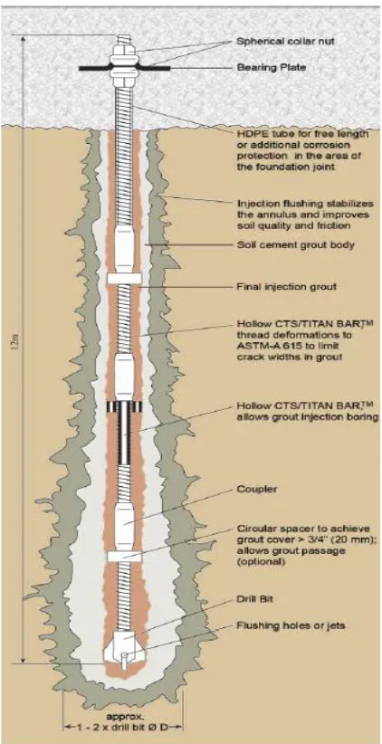
(Fig. 2.1). They are typically reinforced by solid central bar that occupies about one-third
of the whole volume. The grout is placed by gravity, under pressure or by a combination
of both (post grouting). Thus, micropiles can be considered as small drilled-shafts (Cadden
et al., 2004). Micropile typically derives its load resistance from the skin friction between the grout and surrounding soil. Consequently, its capacity varies depending on the size and
subsurface profile of its grout body. This grout body is formed during micropile installation
as a result of injecting grout with or without pressure (Juran et al., 1999). Besides, this
grout body increases the corrosion resistance of the steel reinforcement of micropiles
(FHWA-NHI, 2005) (Fig. 2.2). Realizing the importance of grout, the Federal Highway
Administration Guidelines for Micropiles Design and Construction had set a minimum
Figure 2.1: Micropiles system components (After micropiles brochures-TITAN Ltd.)
Figure 2.2: Typical Cross section for micropiles (After Con-Tec system Ltd., 2011)
On the other hand, cement, the main component of grout, is a major contributor to
the climate change. Each ton of Portland cement production emits approximately one ton
of carbon dioxide (CO2) into the atmosphere (Meyer, 2009). In addition, it consumes
Threaded Bar
Centraliser
Coupling Nut
Drilling Bit
substantial natural resources and energy. In order to achieve green construction, cement
can be partially replaced by inert materials, or by supplementary cementitious materials
(SCM’s) such as fly ash, silica fume, and ground granulated blast furnace slag (Sato, 2006).
To add a new material as a replacement of cement, it should have proper properties in order
to be used as an efficient material in construction applications. These materials should
satisfy the specifications determined by its application. In addition, the effect of these
materials on the environment should be controlled to achieve a non-harmful, environment
friendly performance (Remond et al., 2002).
The following section provides a brief description of the worldwide micropile
classification systems and their design considerations. This will be followed by a review
of the published research addressing the potential of implementing different industrial
wastes in construction applications. Special attention is given to hollow bar micropiles and
the use of treated oil sands drill cutting waste.
2.2.
MICROPILES CLASSIFICATION
Micropiles have been used worldwide in many structural applications. These applications
included seismic retrofitting applications, underpinning of existing foundations, foundation
systems for abutments and piers, wind turbines, transmission and communication towers,
and for slope stabilization applications. Figure 2.3 shows a number of popular applications
of micropiles. Various types of micropiles are employed in these different applications
(Drbe, 2013). Therefore, the Federal Highway Administration (FHWA-NHI, 2005)
classification) and ii) based on methods of grouting (i.e. construction classification). In the
following subsection these types will be explained.
Seismic Retrofiting Underpinning existing
foundations
Resisting uplift/dynamic loads
Arresting Structural
Settlement Reticulated pile wall Excavation Support
Figure 2.3: Different applications for micropiles (After Hayward Baker Inc. ,2015)
2.2.1. Design Classification of Micropiles
In accordance with the FHWA NHI (2005), micropiles are classified based on the
philosophy of behaviour into two different case types:
Case 1: Micropiles are loaded directly. Loads are resisted structurally by the steel
reinforcement and geotechnically by the grout/ground interaction and the end
bearing resistance through the grouted section. This case of micropiles can be used
Case 2: Micropiles are used in a reticulated arrangement such that they serve as reinforcing
to the soil to create a composite mass system to resist the applied loads (Fig. 2.5).
Usually, micropiles are used as structural support which means they are categorized
as Case 1 design philosophy.
Figure 2.5: CASE 2 micropiles (After FHWA, 2005)
2.2.2. Construction Classification of Micropiles
Many factors in the construction of micropiles are affecting their performance. For
instance, drilling method, which highly affects the bond between the grout and the soil,
reinforcement type and grouting methods. However, grouting method is the most sensitive
1997, Drbe, 2013). Therefore, construction classification based on the grouting methods
was established as follows:
Type A: In this type, neat cement or sand-cement is used and placed under gravity pressure
no extra pressure is applied in construction.
Type B: A pressure ranging from 0.5 MPa to 1 MPa is applied to inject the neat cement
grout during construction while a temporary drill casing is placed.
Type C: In this type of micropiles two steps process are applied, first neat cement grout is
placed under gravity pressure in the drilled hole same concept of type A. Before
the primary grout harden same grout mixture is place under a minimum pressure of
1 MPa via a preplaced sleeved grout pipe.
Type D: Another two steps process method; first the neat cement grout is placed under
gravity pressure only, as in type A. After several hours when the initial grout
hardens, additional grout is injected through a sleeved grout pipe under high
pressure ranging from 2 MPa to 8 MPa. A packer can be used in order to enable a
specific horizon to be treated several times. The four presented types (A to D) are
shown in Fig. 2.6.
Type E: This type is an addition to the original types presented by the (FHWA-NHI, 2005)
(A to D). This type consists of a threaded hollow bar connected to a drilling bit, the
hollow bar is drilled and advanced through the soil using air, water, or grout. The
gourd is injected under a pressure up to 1.4 MPa through the hollow bar passing the
Fig. 2.7. This type will be the focus of this research, hence, a detailed explanation
is provided in the following section.
Figure 2.6: Micropile classification system based on method of grouting (After
Figure 2.7: Type E hollow bar micropile (After Con-Tec system Ltd., 2011)
2.3. HOLLOW BAR MICROPILE (TYPE E)
In Type E micropile, a threaded hollow bar is replacing the solid central mono bar used in
Types from A to D (Fig. 2.8). One of the main advantages of Type E micropiles is the fast
installation process. The process for placing Type A to D requires a number of steps, from
the grout (Abd Elaziz and El Naggar, 2012). On the other hand, hollow bar micropiles act
as a drilling rod and reinforcement component at the same time, then the grout is injected
to the hollow bar and passing to the soil through the nozzles found in the drilling bit (Drbe,
2013).
Type E micropiles is composed of three main components as shown in Fig. 2.9 a)
a threaded hollow steel bar, b) a sacrificial drilling bit that has two or more nozzles, and c)
couplers to attach the hollow bars in order to reach the desired depth during installation.
To install Type E micropile, the hollow bar is drilled into the soil using the drilling bit with
air and/or water and/or grout flushing technique. The grout is usually injected at a pressure
up to 1.4 MPa.
Figure 2.8: Solid bar micropile with casing and hollow bar micropile (modified after
Williams Form Engineering Corp., 2011)
Grout Hollow bar (Injection
bar)
Soil Threaded
solid Bar
Steel Casing Steel Casing Threaded solid Bar
Grout Hollow bar (Injection bar)
Figure 2.9: Hollow-bar micropile parts (modified after Williams Form Engineering
Corp., 2011)
2.4. LOAD TRANSFER MECHANISMS OF MICROPILES
Previous study, conducted by (Bruce and Yeung, 1984) based on 5 m pile with a diameter
of 20 cm, showed that skin friction is the main contributor to the geotechnical capacity of
micropiles. It was reported that a settlement of 10% to 20% of the micropile diameter is
needed to mobilize its bearing capacity, compared with only 0.5% to 1% to mobilize the
maximum skin resistance. Therefore, Juran et al. (1999) proposed that micropile should be
designed considering load transference through the shaft resistance only. Lately,
(FHWA-NHI, 2005) stated that the maximum applied compression and tension loads must be
the bond length of the micropile. Therefore, in most cases, micropiles attain their load
carrying capacity mainly through skin friction rather than end bearing. This was confirmed
by a field study conducted by (Drbe and El Naggar, 2013) on four hollow bar micropiles
in a firm to stiff clay.
2.5. DESIGN PHILOSOPHY
Micropiles should be designed for both structural and geotechnical capacities in order to
sustain the anticipated loading conditions at tolerable stress levels following the accepted
displacement levels. The following section will illustrate different methods for evaluating
the structural and geotechnical capacities of micropiles.
2.5.1. Structural Design of Micropiles
Each part of the micropiles contributes to loads transference to a deeper and stronger
stratum. Structural loads are mainly resisted through the reinforcement component, and the
geotechnical capacity of the grout/ground bond zone. A number of equations can be
utilized for calculating the micropiles capacities under compression and tension:
Under compression, according to FHWA (Eq. 2.1):
Pc-allowable = 0.4 fc̍ Ag + 0.47 fy As (Eq. 2.1)
Under compression, according to IBC (International Building Code) (Eq. 2.2):
Under tension, according to FHWA (Eq. 2.3):
Pt-allowable= 0.55 fy As (Eq. 2.3)
Under tension, according to IBC (International Building Code) (Eq. 2.4):
Pt-allowable = 0.60 fy As (Eq. 2.4)
Where: Pc-allowable is the allowable structural axial compression load of the micropile, P
t-allowable is the allowable structural axial tension load, fc’ is the compressive strength of the
grout (typically after 28-days), fy is the yield stress of steel, Ag is the area of the grout in
micropile section, and As is the steel area in the micropile section (bar + casing).
2.5.2. Geotechnical Design Capacity of Micropiles
Micropiles are generally considered as friction piles (FHWA-NHI, 2005). The large contact
area along its length results in a significantly higher skin friction contribution than end
bearing. Moreover, in Type E, the innovative technique in grouting during installation
leads to a higher grout/ground bond capacity resulting in a negligible end bearing effect.
Hence, the geotechnical capacity of micropiles is evaluated through the uncased length
only. This length is described as the bond length of micropiles. Geotechnical capacity of
micropiles can be estimated using the following equation (Eq. 2.5) provided by
(FHWA-NHI, 2005):
Pult=αbond ×π ×Dbond × (bond length) (Eq. 2.5)
Where: αbond is the grout to ground bond estimated by (FHWA-NHI, 2005), Db is the
section of micropile. Table 2.1 provides the suggested values by (FHWA-NHI, 2005) for
αbond. These values depend on the ground conditions and installation techniques during the
construction of micropiles. It is clear that the contribution of end bearing resistance in the
geotechnical capacity of micropiles is neglected due to the small diameter of micropiles
(FHWA-NHI, 2005).
Table 2.1: Grout-to-ground bond values
Soil/Rock Description
Grout/Ground Bond Ultimate Strengths Typical Ranges (kPa)
Type A Type B Type C Type D
Silt & Clay (Some Sand)(Soft,
Medium Plastic) 35-70 35-95 50-120 50-145
Silt & Clay (Some Sand) (stiff,
dense to very dense) 50-120 70-190 95-190 95-190
Sand (Some Silt) (Fine, Loose to Medium Dense) (stiff, dense to very dense)
70-145 70-190 95-190 95-240
Sand (Some Silt, Gravel)
(Fine-Coarse, Medium to Very Dense) 95-215 120-360 145-360 145-385
Gravel (Some sand) (Medium to
Very Dense) 95-265 120-360 145-360 145-385
Glacial Till (silt, Sand, Gravel) (Medium to Very Dense, Cemented)
95-190 95-310 120-310 120-335
Soft Shales (Fresh to Moderate
Fracturing, Little to no Weathering) 205-550 N/A N/A N/A
Slates and Hard Shales (Fresh to Moderate Fracturing, Little to no Weathering)
515-1380 N/A N/A N/A
Limestone (Fresh to Moderate
Fracturing, Little to no Weathering) 1035-2070 N/A N/A N/A
Sandstone (Fresh to Moderate
Fracturing, Little to no Weathering 520-1720 N/A N/A N/A
Granite and Basalt (Fresh to Moderate Fracturing, Little to no Weathering)
2.6. REVIEW OF PREVIOUS STUDIES
Many field and laboratory investigations had been performed in order to evaluate the actual
performance of micropiles. In parallel with field tests, several numerical studies were
conducted considering different types of micropiles. Moreover, the load transfer
mechanisms had attracted the attention of many researchers and many theories were
proposed. A review of the available literature on micropiles is presented in the following
section.
2.6.1. Case Studies for Micropiles
In three case histories reported by Traylor et al. (2002), micropiles Type A were used in a
karst ground to provide structural support and act as a foundation system. The micropiles
working load ranged between 600 to 1000 kN in compression. The average ultimate bond
values of used micropile in massive hard rock were more than 17.5 MPa. They argued that
for anchors in rock, bond lengths greater than about 3m rarely produce much increase in
capacity.
A comparison between the calculated allowable capacity based on different codes
guidelines and loading test results for micropiles with outer diameter of 178 mm installed
into a 203 mm drill hole were summarized by Cadden et al. (2004). It was found that the
allowable structural capacity based on the codes ranged from about 800 to 2100 kN, while
load tested micropiles exhibited about double these values without displaying any sign of
failure. These findings demonstrated that most codes underestimate the capacity of
Jeon (2004) examined the load-displacement behaviour of Type B, C and D
micropiles constructed in cohesive soils and sand under axial compression tests. The
capacity of the micropiles was compared with the design values for drilled shafts. The
results showed that micropiles possess higher unit skin friction compared to
larger-diameter drilled shafts (i.e. around 1.5 to 2.5 the values for drilled shafts). This increase
was attributed to the different grouting methods applied during micropile installation.
Holman and Tuozzolo (2006) analyzed three micropile load tests from two case
histories. Two of the three micropiles were tested to plunging failure and one to impending
failure. They found that the load distribution in the bond zone of the tested micropiles was
generally non-uniform, indicating that the mobilized unit bond stress was not constant.
2.6.2. Case Studies for Hollow Bar Micropiles
Hollow bar micropiles were presented recently in the industry. Therefore, research done to
evaluate the performance of this type of micropiles is not intensive.
The performance of hollow bar micropiles in five different projects was studied by
Bishop et al. (2006). The hollow bar micropiles were installed in different soil types. A
high skin friction was noticed in the performed tests, which allows carrying moderate to
moderately high loads. They also determined the capacity of a pile group by calculating
the sum of the individual micropiles.
In another study performed by Gómez et al, (2007), the performance of 260 hollow
bar micropiles was investigated. In this investigation, a grout flushing technique was used
in the installation of micropiles. They reported that hollow bar micropiles have an
greater values of grout-to-ground bond for the provided values in accordance with type B
micropiles.
Verification compression and tension loading tests were conducted on hollow bar
micropiles by (Telford et al., 2009). The tested micropiles were installed in cohesionless
soil to a depth of 9.8 m. The results of the verification tests confirmed that micropiles can
support high compression load greater than 1300 KN with small movement of the pile
head. They also considered in their investigation an enlarged pile diameter of 1.5 times the
drill bit diameter. The calculated grout-to-ground bond strength values were close to values
proposed by (FHWA-NHI, 2005).
Four pairs of micropiles installed in a layer of soft clay/sandy clay/very loose to
loose clayey sands, were tested by Bennet and Hotherm (2010). The tested piles had depths
of 7 m, 8.5 m, 10 m, and 11.5 m. The axial capacity of the shortest pile was 480 kN and
460 kN for the 150 mm clay bit and the 115 mm cross bit, respectively.
Five hollow bar micropiles were examined by Abd Elaziz and El Naggar (2010,
2011, and 2012). All micropiles were installed in cohesive soils. All micropiles had a
constant outer diameter of 76 mm, and connected to a 178 mm carbide drill bit. The results
showed that considering hollow bar micropiles as type B underestimates the
grout-to-ground bond strength.
Four hollow bar micropiles installed in a firm to stiff clay were tested by (Drbe and
El Naggar, 2013). The installed hollow bar micropiles had a diameter of 178 mm, and were
constructed using two different carbide drill bit of 178 mm and 228 mm. The installation
micropiles diameter of 10% to 20% for the different types of drill bit. They also have
indicated higher values of grout-to-ground bond strength, than the values presented by
(FHWA-NHI, 2005).
2.6.3. Analytical and Theoretical Analyses
Misra et al. (2004) proposed analytical relationships to describe pullout load-displacement
behaviour for micropile–soil interaction. Micropile was considered as partially bonded
with a top debonded zone and a bottom bond zone. Moreover, it was assumed that the
micropile–soil interface has elastic-perfectly plastic behaviour and homogeneous, hence,
the effects of soil layering and grout inhomogeneity were averaged. Their model provided
good predictions for field measured load-displacement curves of different case studies.
The effect of buckling on the capacity of micropiles was considered by Cadden and
Gomez (2002). They produced a graphical chart based on the Euler buckling equation
which can be used as a useful tool to check buckling of a given micropile section. However,
they neglected the grout effect on the buckling behaviour. These graphs were reproduced
by the FHWA NHI (2005).
2.6.4. Numerical Analysis
Ousta and Shahrour (2001) investigated the seismic behaviour of micropiles used for the
reinforcement of saturated soils. The fluid-soil coupling and a cyclic elasto-plastic
constitutive relation were used to describe the soil behaviour in three-dimensional finite
element analysis. They showed that micropiles have slight effect on earthquake-induced
under seismic loading leading. Moreover, Sadek and Shahrour (2004) analyzed the
influence of micropiles inclination on their response to seismic loading using
three-dimensional finite element modeling. Their results showed that the micropile inclination
improved the seismic performance compared to vertical micropiles. The inclination
allowed a better mobilization of the axial stiffness of micropiles leading to lower shearing
forces and bending moment induced by seismic loading. Additionally, Sadek and Shahrour
(2006) investigated the influence of the head and tip condition on the seismic performance
of micropiles installed in linear elastic soil. They showed that the pinned connection
between the micropiles and their cap reduced the axial force and bending moment in
micropiles. In addition, embedment of the micropiles tip in a stiff layer resulted in a
significant increase in the induced internal forces by seismic loading.
2.7. IMPLEMENTATION
OF
INDUSTRIAL
WASTE
IN
CONSTRUCTIONAL APPLICATIONS
The objective of this section is to investigate the potential use of different wastes in
construction applications. This part is based on the comprehensive review of available
literature on use of waste in construction materials. Usually, the production of different
construction materials impacts the environment adversely. Besides, the disposal of
industrial wastes has become a major concern for industry due to environmental controls
On the other hand, reusing industrial waste in construction applications represents
an environmentally sustainable practice (Carignan et al., 2007). Many researchers
investigated different options for the reuse of wastes in construction applications. Different
industrial wastes can be implemented in cementitious materials as components of binder,
as a replacement aggregate, or as additives, which can modify their fresh and hardened
properties (Helmuth, 1987; Cheng-yi and Feldman, 1985; Singh and Garg, 1999; Aggarwal
and Siddique, 2014). However, to utilize a new material it should satisfy the specifications
determined by its applications. Also, it should have no harmful effect on health or
environment (Remond et al., 2002).
2.7.1. Case studies for Reusing of Waste Materials in Constructional Applications
Tuncan et al. (2000) investigated the petroleum-contaminated drilling wastes, to be used
as sub-base material for road construction. In this study, the petroleum waste was stabilized
by mixing pozzolanic fly ash, lime and cement. The physical, mechanical, and chemical
properties of the new material were studied. They noted an improvement in the properties
of the stabilized specimens in comparison with the un-stabilized ones. They also proposed
an optimum mixture proportions.
The reuse of water based mud drilling wastes (WBM) in construction applications
was presented by Page et al. (2003). They studied the potential of using the waste material
in four different applications; cement manufacture, road pavements, bitumen and ready
mix. They have concluded that the WBM drilling wastes have the potential to be
the drill cuttings was required, which included; washing (to remove sulphate, chloride and
soluble metals) and oil removal.
The effect of waste material addition in geo-grid applications was investigated by
Sivakumar and Glyn (2004). They have studied the effect of quarried basalt, quarry waste,
building debris and crushed concrete on the performance of geo-grids. Tests performed
included direct shear tests in wet and dry conditions and crushability tests. Results showed
a satisfactory performance for the geo-grid with the waste material. However, it was
noticed a weakness in the crushability of the tested materials when subjected to repeated
loading rates.
Hassan et al. (2004) have studied the potential uses of petroleum contaminated soil
in highway construction. Their investigation included the stabilization of the tested soil
with cement, crushed stone aggregate and using it as a fine aggregate replacement in hot
mix asphalt concrete. They also have performed a toxicity characteristic leaching
procedure (TCLP) on the tested specimens. TCLP test results showed that the investigated
soil was non-hazardous. The unconfined compressive strength of the cement-stabilized
contaminated soil at a percentage up to 5%, and remained relatively constant with the
increase of cement content. They also noticed an adverse effect on the cement hydration
caused by the addition of the waste. However, the tested waste still showed a good potential
to be used in road construction.
The use of mine tailings in the construction applications was studied by Mahmood
and Mulligan (2007). They studied the potential of using tailing wastes as a base material
performed on different types of tailing brought from several mines in eastern Canada. The
results showed that all tested tailings have exceeded the minimum strength requirements
for filling underground stopes. Moreover, a decrease in strength as the water cement ratio
increases for all tailings was noticed. They suggested that tailing wastes can be used as a
base material for the building of unpaved temporary access roads.
Another study performed by Chen et al. (2007) on the recycling of drill cutting
wastes from three different locations, in construction applications. In this experimental
study, mechanical properties of permeable brick and concrete manufactured with the waste
material were evaluated. A decrease in the compressive strength of the brick produced
using drill cutting waste in comparison to the pure cement bricks was reported.
Hassan et al. (2007) have investigated permeability and leaching of hot mix asphalt
in concrete containing oil-contaminated soils (OCS). The OCS was added as a replacement
of fine aggregate in the asphalt concrete mixtures with percentages up to 40% by weight.
A significant reduction in the tested asphalt permeability as the percentage of OCS
increased up to 30% was noticed. The results also showed satisfactory limits for heavy
metals leaching.
Guney et al. (2010) have investigated the reuse of waste foundry sand in the
production of high-strength concrete. The natural fine sand in concrete was partially
replaced with foundry waste at rates of 0%, 5%, 10%, and 15%. Fresh and hardened
properties of the tested materials were examined. A decrease in the compressive and tensile
They also reported a reduction in freezing and thawing cycles, however, all the measured
propertied were still within the acceptance limits of the ACI code.
Misra et al. (2011) investigated using the oil drill cuttings in construction of roads.
They concluded that drill cuttings waste has a high potential to be used in the road
construction as it can present a stable and strong sub-grade for roads with minimal amount
of heavy/toxic metals, which means that the waste can be safely used in road construction.
Mohammed and Cheeseman (2011) investigated the use of waste oil drill cuttings
treated by thermal desorption in sandcrete blocks. Their results showed that replacing sand
with the treated waste up to 50% had enhanced the density and thermal conductivity of the
tested materials. Compressive strength of different specimens was comparable to that of
the control specimen. They concluded that the treated waste had the potential to be used in
the production of sandcrete blocks.
Kamei et al. (2012) investigated the reuse of recycled bassanite produced from
gypsum waste in conjunction with coal ash as a stabiliser material to enhance the strength
of very soft clay soil. They also investigated the effect of bassanite addition on the
durability of soft clay. In this study, the waste was added with percentages varying from
0% to 20%. Results showed that the use of recycled gypsum waste with coal ash has
increased the strength and improved the durability of the investigated soil. They also
noticed a decrease in the mechanical properties of the tested samples when the coal ash is
added without bassanite. On the other hand, their results showed that the incorporation of
bassinite with coal ash had decreased the durability and strength of the stabilized soil when
Ahmed (2013) studied utilizing recycled bassanite produced from gypsum waste to
enhance the mechanical properties of weak subgrade clay soils used in roads construction.
The recycled bassanite was mixed with furnace slag cement with a ratio of 1:1 to prevent
the solubility of bassanite. The results showed that the addition of bassanite had enhanced
the stability of weak roadway subgrades clay soils. It was also noticed an increase in the
mechanical properties of the tested soils when the amount of bassanite increased. It was
concluded that the use of bassanite enhanced the performance of the tested soil, which
would extend roads service life leading to environmental and economic benefits.
Irali et al. (2013) investigated the effect of recycled concrete aggregate in the
construction of concrete pavements. They studied the behaviour of four pavement test
sections constructed using the recycled concrete aggregate for a period of five years. The
effect of environmental factors such as temperature and moisture gradients on long term
performance of pavement was studied. Their results showed comparable performance of
the investigated pavements and the control pavement. They suggested that the use of waste
concrete content is feasible in the construction in concrete pavements.
2.7.2. Treated Oil Sands Drill Cuttings Waste
Oil sands located in northern Alberta is considered the second largest oil reserve in the
world after Saudi Arabia Fig. 2.10 (ERCB, 2010). It can cover more than 170 billion barrels
of bitumen (Alberta oil sands industry quarterly update, 2014). Generally, oil sands extend
to a depth from 30 to 90 meters below the ground surface. Oil sands are composed of 8 to
14% (by weight) bitumen and 3 to 5% (by weight) water, the rest are mineral solids (sand,
Figure 2.10: Alberta’s oil sands areas (ERCB, 2010)
The bitumen is extracted from the sand by one of two methods. The first method is in-situ
mining, which is suitable for bitumen lying deeper than 70 m under the ground surface Fig.
2.12. In this process, bitumen is treated thermally to a temperature above 250°C to reduce
its high viscosity and then pumped easily to the ground.
Figure 2.12: In-situ mining (Gosselin et al., 2010)
The second process is open pit mining, also known as hot water process, is suitable for oil
sands with depth up to 70 m. In this process, oil sands are excavated, crushed and
transported into hot water in a temperature between 45 °C and 60 °C to make slurry. Then,
air bubbles are pumped carrying the bitumen droplets to the surface, while the solids settle
Figure 2.13: Open pit mining (Gosselin et al., 2010)
The resulting products from this process are bitumen and tailings (warm aqueous
suspension of sands, silt clay and residual bitumen). The tailings are pumped into large
tailing ponds, then the coarse sand settles, while the residual bitumen are carried as slurry.
A critical part in this process is the disposal of sands tailing. The current volume of tailing
is more than 720 million m3 and this number keeps increasing with the extraction of oil
sands. Also, a study done by Mackinon et al. (2005) showed that the contaminated tailing
water reached the ground water level. All these issues have led to an urgent need to find
new innovative methods for disposing the oil sands tailing.
One of the recent technologies for the oil sands waste treatment is the