Electronically Steerable Smart Antenna-A
Comparative Study
Jinimol Baby 1 , Noble C Kurian 2
M.Tech Student, Department of ECE., SNGCE, Kadayiruppu, Kolenchery, Kerala, India1
Assistant Professor, Department of ECE, SNGCE, Kadayiruppu, Kolenchery, Kerala, India2
ABSTRACT: The need for wireless applications has grown to a great extend . ESPAR antenna is a promising
structure for low cost smart antenna system, that can full fill the requirement in wireless communication systems. Electronically Steerable Passive Array Radiator (ESPAR) antennas are proposed for low cost smart antenna and it works by using analog adaptive beam forming. The configuration and design of these antennas and some simulation results, especially based on their beam or null steering capability. The input impedance at the driven element is affected by the capacitive loading at the parasitic elements, it leads to impedance mismatching. .To avoid this problem there are many studies taken in this area. The challenges and issues involved in improving ESPAR antenna systems are discussed in detail and provide the best method to modify the ESPAR antenna with low cost, low power consumption and small size.
KEYWORDS: Smart antenna; ESPAR antenna; Beam forming.
I. INTRODUCTION
The smart antennas provide high data rate and high quality of data services and that have capability of adaptive beam forming in accordance with the signal environment. The adaptive beam forming reduces the signal interference. Shannon's theorem says ,lesser the interference more will be the channel capacity. Traditional smart antennas are composed of several radiating elements in the form of a digital beam forming array, they are quite expensive. The main disadvantages of traditional smart antennas are high cost, large power consumption and a large size. For commercial applications, we have to reduce the cost, size and power consumption of a smart antenna system.
ESPAR antennas are consist of one driven element and several parasitic elements. These types of antennas are reduce the size, cost and power consumption.In a multi element antenna array the driven element is the element in the antenna which is electrically connected to the receiver or transmitter. In a transmitting antenna it is driven element is excited by the RF current from the transmitter, and it is the source of the radio waves. In the receiving antenna it collects the incoming radio waves for reception, and converts them to the tiny oscillating electric currents, which are applied to the receiver. Multi element antennas consist of a driven element, connected to the receiver or transmitter then passed through one feed line, and a number of other elements which are not driven, it is known as parasitic elements. The ESPAR antenna has a tightly coupled structure, the capacitive loading in the parasitic elements affects the input impedance at the driven element and it leads to impendence mismatching. To avoid this problem ,many methods has been found. But most of the methods are focused only on reducing the capacitive loading. By reducing the capacitive loading the size is also increased. There is one method ,which reduces the impedance mismatching without reducing the capacitive loading.
II. RELATED WORKS BASED ON ESPAR ANTENNA
i. ESPAR Antenna
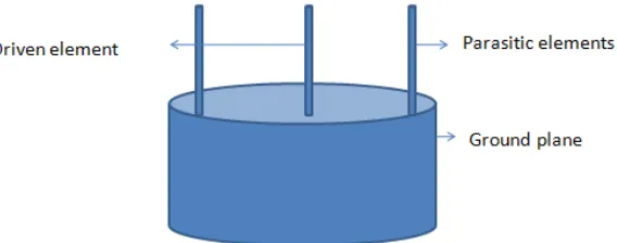
varactors. The most widely used ESPAR antenna is composed of several quarter wavelength monopoles. For a standard quarter wavelength monopole ESPAR antenna with main pattern in horizontal plane, the distance between driven element and parasitic elements are quarter wavelength. Each parasitic elements are excited for some time. Each parasitic element is excited with different information with respect to the nulls and beams.
Fig. 1. Basic ESPAR antenna( side view)
The side view of the basic ESPAR antenna is shown in the figure 1.In the basic ESPAR antenna, the tightly coupled structure of driven elements and parasitic elements are leads to the problem of impedance mismatching. Because the input impedance at the driven element is affected by the capacitive loading at the parasitic elements.
ii. DEESPR Antenna
Dielectric Embedded ESPAR antenna is a improved model of ESPAR antenna. This antenna array for mobile wireless communication is developed by using the finite element method. DE-ESPAR antennas are developed for the size reduction of the basic ESPAR antenna. The size reduction of the seven element monopole antenna is accomplished by embedding the antenna array in to the dielectric material. A cylindrical rod of FIK ceramic complex with a relative permittivity around 4.5 is commonly used as the dielectric material.
DE-ESPAR antenna have several parasitic elements with one driven element, like the ESPAR antenna. The beams and nulls are steer electrically. Because of the small structure it consumes less power to operate the array counterparts. Base loaded monopoles are used as the parasitic elements. This is helps to reduce the size of the antenna. The only difference between the ESPAR and DEESPAR antenna is the usage of homogeneous dielectric material. This type of antennas are present with the micro strip transmission line loads producing the maximum gain of 5.1 dBi.
Fig.2. DE-ESPAR antenna
iii. Dual Band ESPAR Antenna
antenna to the wireless LAN system , the radiation patterns of each frequency has to be formed at the same time and they are controlled independently. In this type of antenna only one centre element is excited by the RF signal. There are consist of six parasitic elements for each frequency band, and are surrounded the centre element. Height of each parasitic element is only quarter wavelength as same as the ESPAR antenna.
In dual band ESPAR antenna, a low pass filter is used between the parasitic element for 2.4GHz and varactor. The cut off frequency of the low pass filter is in between 2.4 GHz and 5.2GHz.LPF is used for suppressing the reactance fluctations at 5.2GHz in the case of varying the reactance of 2.4GHz parasitic elements. There is no filter is required between the parasitic element for 5.2GHz and variable reactance, because of the excitation due to parasitic element for 5.2GHz is negligible at 2.4GHz.The dual band ESPAR antenna is shown below.
Fig.3. Dual band ESPAR antenna
iv. Electronically Steerable Smart antenna
The electronically steerable smart antenna solve the impedance mismatching problem of the basic ESPAR antenna. It is also known as improved ESAR antenna. In this type of antenna it has the same structure of the common ESPAR antenna. Electronically steerable smart antennas replaces the parasitic monopole elements by using the folded monopole parasitic elements. By using the folded monopole as the parasitic element , it provide large capacitive loading. The folded monopoles are just bent towards the driven element. It also helps to reduce the size of the antenna. For the height reduction of the ESPAR antenna the top loaded monopoles are used as the driven element.
Fig. 4. Electronically Steerable Smart Antenna
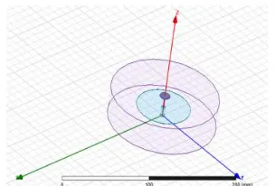
Fig. 5 Design of Monopole Antenna using HFSS
Fig. 6 Design of ESPAR Antenna designed using HFSS (a) full stucture (b) Side view (c) Top view
Then we use the folded monopole as parasitic elements to reduce the impedance mismatching ,without reducing the capacitive loading.The design of ESPAR antenna is shown in figure 6.
III. COMPARISON OF DIFFERENT ESPAR ANTENNAS WITH ELECTRONICALLY STEERABLE SMART ANTENNA
The rapid growth of the wireless communications in the market has resulted in new technologies being investigated to improve the performance and usage of the available spectrum in the most efficient way. The ESPAR antennas with controllable directionality is one of the promising technology for wireless communication. This come in to the market by solving the problem of the traditional smart antennas. The ESPAR antenna is also known as a smart antenna. The main problem of the ESPAR antenna is impedance mismatching. Many researches has been take place in the area of ESPAR antenna to solve the problem. In Dielectric Embedded ESPAR antenna, the ESPAR antenna is embedded in to a dielectric material. This helps to reduce the size of the antenna and also reduces the power consumption. In this dielectric embedded electronically steerable parasitic array radiator antenna, there is strong electromagnetic coupling between the elements in dielectric material ,and the interface matching between the air and high dielectric materials. The finite ground structure make the antenna's analytic solution become very complex. These antennas also have the problem of impedance mismatching. Dual band ESPAR antenna is a another type of ESPAR antenna for wireless LAN applications. There is using different length parasitic elements for different frequency bands. This types of ESPAR antennas are designed for 2.4GHz and 5.2GHz bands. As compared to the basic ESPAR antenna, there is used some low pass filters. This is used to avoid the fluctuations . In dual band ESPAR antenna there is still remaining the problem of impedance mismatching and the size is not to be reduced as compared with the basic ERPAR antenna. Electronically steerable smart antenna is a improved method of basic SPAR antenna. The monopoles are replaced by the folded monopoles in the improved ESPAR antenna. And the driven element is replaced by using the top loaded antenna. This helps to reduce the size and increase the capacitive loading. The electronically steerable smart antenna solve the impedance mismatching problem of the basic ESPAR antenna. Instead of eliminating the capacitive loading, the electronically steerable antenna takes the advantage of capacitive loading to reduce the size of the antenna. By using tightly coupled structure of the folded monopoles, an ESPAR antenna with height less than can be achieved. Electronically steerable smart antenna has small size as compared to other ESPAR antennas. The electronically steerable antenna also reduces the power consumption.
IV. CONCLUSION
Electronically steerable antenna is the most efficient smart antenna for the wireless communication applications. It solve the problem of smart antennas and it is a improved method of basic ESPAR antenna. The ESPAR antenna is a low cost ,small size antenna. But it have some problem in impedance matching. There are several modifications are done in ESPAR antenna. The electronically steerable antenna reduces the impedance mismatching and it also reduces the cost and size of the antenna as compared with the ESPAR antenna. This antenna is very easy to manufacture.
REFERENCES
1 Hai-Tao Liu, Steven Gao, and Tian-Hong Loh, "ectrically Small and Low Cost Smart Antenna for Wireless Communication" IEEE transactions on antennas and propagation, Vol. 60, no. 3, march 2012
2 H. Liu, S. Gao, and T. Loh, "Compact-size electronically steerable parasitic array radiator antena" in Proc. LAPC, Nov. 16–17,pp. 265– 268, 2009.
3 T. D. Dimousios, C. I. Tsitouri, S. C. Panagiotou, and C. N. Capsalis, "Design and optimization of a multipurpose tri-band electronically steerable passive array radiator (ESPAR) antenna with steerablebeam pattern for maximum directionality at the frequencies of 1.8, 1.9 and 2.4 GHz with the aid of genetic algorithms," in Proc. LAPC, Mar. 17–18, pp. 253–256, 2008.
4 J. Lu, D. Ireland, and R. Schlub, "Dielectric embedded ESPAR (DEESPAR) antenna array for wireless communications," IEEE Trans. Antennas Propag., vol. 53, pp. 2437–2443, Aug. 2005.
5 O. Shibata and T. Furuhi, "Dual-band ESPAR antenna for wireless LAN applications," in Proc. IEEE Antennas Propag. Soc. Int. Symp.,vol. 2B, pp. 605–608, Jul 3–8, 2005 .
7 R. Schlub, L. Junwei, and T. Ohira, "Seven-element ground skirt monopole ESPAR antenna design from a genetic algorithm and the finite element method," IEEE Trans. Antennas Propag., vol. 51, no. 11, pp. 3033–3039, 2003.
8 R. Harrington, “Reactively controlled directive arrays,” IEEE Trans. Antennas Propag., vol. AP-26, no. 3, pp. 390–395, May 1978. 9 Q. Wang and Z. Shen, “Modal expansion analysis of electrically steerable passive array radiators (ESPAR),” in Proc. IEEE Antennas
Propag.Soc. Int. Symp., vol. 4B, pp. 27–30, 2005.
10 Y. Ojiro, H. Kawakami, K. Gyoda, and T. Ohira, “Improvement of elevation directivity for ESPAR antennas with finite ground plane,” in Proc. IEEE Antennas Propag. Soc. Int. Symp., vol. 4, pp. 18–21, 2001.
11 M. Carras, A. Kalis, and A. G. Constantinides, “Improving the frequency characteristics of the electronically steerable passive array radiator antenna,” in Proc. 1st Int. Symp. Wireless Commun. Syst., Sep. 20–22, pp. 130–134, 2004.
12 R. Schlub, L. Junwei, and T. Ohira, “Frequency characteristics of the ESPAR antenna,” in Proc. APMC, vol. 2, pp. 697–700, Dec. 3–6, 2001.
BIOGRAPHY
Jinimol Baby 1 is a PG student at SNGCE, Kolenchery ,Kerala, India. She received B.Tech degree in Electronics
and communication Engineering from MG University, Kerala in 2014 and currently pursuing M.Tech in communi- cation engineering from the same university.
Noble C.Kurian 2is working as an assistant professor in the department of Electronics and Communication at SNGCE,