Abstract
O’Neill, Adrian Thomas. Development of Closed Cell Metallic Foam Using Casting Techniques. (Under the Direction of Dr. Afsaneh Rabiei.)
The research sited in this paper involves the development of a new metal foam composite
material using casting techniques. This work included the design of the material and the
development of a process to produce the metal foam. The materials used to produce the
foam consisted of low carbon steel hollow spheres and an aluminum alloy. The foam is
comprised of steel hollow spheres packed into a random dense arrangement, with the
interstitial space between spheres infiltrated with a casting aluminum alloy. Using
prefabricated hollow spheres assures a uniform pore size and cell wall thickness. Casting a
metal into the interstitial space provides a solid media to add structural support to the foam.
The goal of this research has been to develop metal foam that demonstrates improvements in
product uniformity and mechanical properties over the currently available foams. To
accomplish this goal, the study included the identification of the various technologies used to
manufacture metal foams, the assessment of the improvements needed to augment the quality
of foamed metals, and the design of a new product and processing technique that
substantiates these goals. The experimental equipment was designed and procured, while the
raw materials were obtained. Then the hollow sphere foam samples were successfully
produced. Using these samples a series of characterization studies was done to qualify and
quantify the results. These findings were then compared to presently published data to gauge
The hollow sphere metal foam developed in this study displayed significant improvements in
the measures of compressive strength and energy absorption capacity, all the while
maintaining the characteristic properties of cellular metals. The improvements were
measured against the next best existing technology. The newly developed foam averaged 67
MPa over a region of 10 – 50% strain, with densification beginning at approximately 50%
strain. The value for energy absorption is 30 MJ/m3 at 50% strain. This foam also has a
strength to density ratio on level with the best reported results to date. The combination of
these properties gives opportunity for use in previously unidentified applications, such as an
energy absorption media for buildings subject to seismic motion. This foam can also be
designed in such applications as automobile crumple zones, as structural members in air and
space craft, and in biomedical prosthesis.
Several areas for improvement have been identified for this technology. The bonding
strength between sphere and matrix needs improvement, and different material choices and
processing changes have been identified in this research to achieve these improvements. The
packing density of the spheres can be improved, and a new method of vibrating the sphere
arrangement prior to molding may increase the packing density. The porosity of the
aluminum matrix can be reduced, and the design of the casting mold and processing
conditions can be modified to reduce undesirable porosity. Additional testing methods have
been identified to further characterize the foam and reveal insights for further improvement.
The iterative process of sampling, characterization, and analysis will continue to improve this
DEVELOPMENT OF CLOSED CELL METALLIC FOAM USING CASTING TECHNIQUES
by
ADRIAN THOMAS O’NEILL
A Thesis Submitted To the Graduate Faculty Of North Carolina State University
In Partial Fulfillment Of The Requirements for the Degree Of
Master of Science
MECHANICAL & AEROSPACE ENGINEERING
Raleigh
Fall 2004
APPROVED BY:
_____________________________________ Dr. Afsaneh Rabiei – Chair of Advisory Committee
_____________________________________ Dr. Jeffrey W. Eischen – Member of Advisory Committee
Dedication
This publication is dedicated to Margaret, my mother, and Elana, my sister, whose
unwavering support has given me the strength and guidance to persevere in achieving my
Personal Biography
Adrian T. O’Neill received his Bachelors of Mechanical Engineering degree in 1998 from the
Georgia Institute of Technology, receiving highest honors. His major area of study was
Mechanical Engineering with a specialization in fluid and thermal systems.
He went on to work at the Goodyear Tire & Rubber Company in Akron, Ohio. At Goodyear,
after doing a hands-on introduction to tire manufacturing in the race tire division, he was an
associate in the passenger tire development division. There he utilized CAD software and
performed finite element analysis in designing and developing tire tread patterns for new
lines of tires. He was awarded ten patents as the co-inventor for novel tire tread designs.
In 2000, he was hired into the consulting firm of Plastic Technologies, Inc. in Toledo, Ohio.
As an associate engineer, he designed, developed and tested packaging for the food industry,
made from polyethylene terephthalate (PET) and polypropylene.
In the fall of 2003, he enrolled as a graduate student at North Carolina State University. He
is currently working towards a master’s degree in Mechanical Engineering with the
Acknowledgements
The research and findings included in this thesis were accomplished with the help and
support of many persons. I would like to acknowledge and thank these persons for the
generous gift of their time and knowledge.
My advisor on this project, Dr. Afsaneh Rabiei, was a consistent source of help and
encouragement. My advisory committee, Dr. Afsaneh Rabiei, Dr Jeffrey Eischen, and Dr.
William Roberts have generously given their time to review my work.
Laboratory testing of samples was accomplished with the assistance of Dr. Sami Rizkalla and
Lee Nelson in Civil Engineering, Dr. Harvey West in Industrial Engineering, and Dr. Dale
Batchelor and Chuck Mooney in the Analytical Instrumentation Facility.
Experimental tools were fabricated by Skip Richardson and Mike Breedlove in the
Mechanical & Aerospace Engineering department machine shop.
My fellow graduate students and members of my group, Brian Neville, Wassim Azzi, and
Elizabeth Baldwin created a co-operative and supportive environment in which we
accomplished whatever the moment required.
My gratitude also extends to the Graduate School of Engineering for the fellowship award
that enabled me to work on this project, and to the National Science Foundation for funding
this research.
I would be remiss not to acknowledge and thank the people of the state of North Carolina for
providing and supporting this great institution in which I have been able to continue my
Table of Contents
LIST OF TABLES...VIII
LIST OF FIGURES ...IX
LIST OF SYMBOLS AND ABBREVIATIONS ...XIII
INTRODUCTION ... 1
Potential Applications 6
Automotive Design 6
Sound Absorption 8
Biomedical Engineering Design 8
RESEARCH OBJECTIVES ... 10
LITERATURE REVIEW ... 12
Liquid Metallurgy Techniques 12
Georgia Tech HSF 13
Processing 13
Characteristics 15
Fraunhofer Hollow Sphere Foam 17
Processing 19
Characteristics 20
Fabrication and Properties of Syntactic Magnesium Foams 21
Processing 22
Characteristics 23
Advantages/Disadvantages 25
Alporas Foam 26
Production Process 26
Characteristics 27
Advantages/Disadvantages 30 Cymat Stabilized Aluminum Foam 30
Characteristics 31 Advantages / Disadvantages 33
EXPERIMENTAL PROCEDURE ... 34
Equipment Used 34
Casting Mold 34
Mold Design 34
Molding Tools 37
High Temperature Furnace 38
Linear Precision Saw 38
Grinding and Polishing Stations 39
Sonic Cleaner 41
Compression Testing Machine 41
Optical Microscope 42
Scanning Electron Microscope 42
Raw materials 44
Hollow Spheres 44
Aluminum Matrix 46
HSF Processing Method 47
Processing Steps 47
CHARACTERIZATION... 50
HSF Density, Relative Density, and Packing Density Determination 50
Relative Density Calculation 51 Packing Density Experiment 52
Compression Testing 55
Compression Testing Photographs 58
Scanning Electron Microscopy 61
Sphere to Matrix Bonding 66
Compositional Analysis 72
Quantitative Compositional Analysis 74
COMPARATIVE ANALYSIS ... 78
CONCLUSION... 82
FUTURE ACTIONS ... 83
List Of Tables
Table 1. Physical And Mechanical Data For Georgia Tech HSF With λ/D = 2, λ/D = 5,
And λ/D = 10. 17
Table 2. Mechanical and Physical properties of Fraunhofer HSF shown in Figure 8 (c). 21
Table 3. Physical And Mechanical Properties Of Magnesium Syntactic Foam. 24
Table 4. Physical And Mechanical Properties Of Alporas Foam. 30
Table 5. Physical And Mechanical Characteristics Of Cymat SAF. 33
Table 6. Typical SEM Settings Used In Imaging HSF Samples. 44
Table 7. Aluminum Alloy Compositions As Delivered By Trialco, Inc. 47
Table 8. Constants Used To Determine HSF Relative Density. 51
Table 9. Results Of Packing Density Experiment. 54
Table 10. Physical And Mechanical Characteristics Of NCSU HSF. 57
Table 11. Qualitative Elemental Analysis On HSF Features. 76
List Of Figures
Figure 1. (A) ERG Duocel Open Cell Foam Used In A Heat Exchanger, And (B)
Alulight Closed Cell Foam Used As Structural Support In A Hollow Beam. 3
Figure 2. Representative Stress Strain Curve for Metal Foams. 4
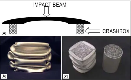
Figure 3. Cymat Corporation (A) Bumper Design Incorporating Crashboxes, (B)
Compressed Crashbox, And (C) Additional Crashbox Designs. 7
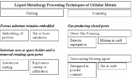
Figure 4. Liquid Metallurgy Processing Techniques Of Cellular Metals. 12
Figure 5. Non-Carburized Fe – 12 Cr Foam Before And After 70% Compressive Deformation. 14
Figure 6. Compressed Stainless Steel HSF Samples Of Varying Sizes, Corresponding
To λ/D Ratios Of 2, 5, And 10. 15
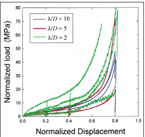
Figure 7. Stress – Strain Behavior Of The Samples Shown In Figure 6. 16
Figure 8. Fraunhofer HSF Samples Made From (A) Various Metals, (B) 316L Stainless Steel, And (C) 316L Stainless Steel. 18
Figure 9. Fraunhofer Powder Metallurgy Production Process For Hollow Spheres. 19
Figure 10. Fraunhofer - Cross Sectional View Of Two Spheres In Contact. 20
Figure 11. Stress Strain Curve Of Fraunhofer 316L Stainless Steel HSF Shown In Figure 8 (c). 21
Figure 12. Infiltration Casting Process Used To Produce Magnesium HSF. 23
Figure 13. Magnesium Matrix / Aluminum Oxide Sphere HSF Samples. 23
Figure 14. (A) Stress Strain Behavior Of Magnesium Syntactic Foam, And (B)
Photograph Showing Shear Band During Compression Deformation. 24
Figure 15. Defects In Magnesium Syntactic Foam (A) Inner Wall Of Hollow Sphere Penetrated By Magnesium Droplet, And (B) Two Hollow Spheres With Incomplete Infiltration Of Magnesium In Interstitial Space And Non-Uniform Wall Thickness.
25
Figure 17. Alporas Foam (A) With Mean Cell Size Of 3.0 mm, And A Cell Size
Distribution (B) Ranging From 1-7 mm. 28
Figure 18. Alporas Foam (A) With Mean Cell Size Of 4.5 mm, And A Cell Size
Distribution (B) Ranging From 1-13 mm. 28
Figure 19. Apparent Density Distribution Of From The Cross Section Of (3) Alporas Foam Samples. The Apparent Density Range Is 0.18–0.24 g/cm3. 29
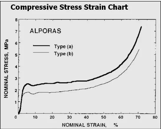
Figure 20. Behavior Of The Two Different Alporas Foams In Compression Testing. The Strain Rate Is 1 x 10⁻³ s-1, And The Mean Cell Sizes Are (a) 3 mm And (b) 4.5
mm. 29
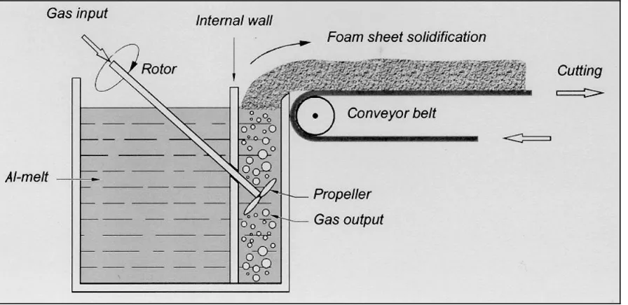
Figure 21. Cymat SAF Production Process: Direct Foaming Of Al-Melt By Gas
Injection. 31
Figure 22. 90x90x50mm Cymat Foam, 10% RD. 32
Figure 23. Stress Strain Curves For Cymat SAF, Relative Density Ranges Between 15.5% - 22.4% And Strain Rates Range Between 10-3 – 10+1. 32
Figure 24. HSF Mold In Various Stages Of Assembly (A) Runner With Gate, (B) Adding The Filter And Side Walls, And (C) Fully Assembled. 36
Figure 25. HSF Mold Shown In (A) Side View And (B) Top View. 36
Figure 26. Molding Tools Used In Casting, Including Tongs, Crucible, And Quartz Stirring Rod. 38
Figure 27. Buehler Isomet 4000 linear precision saw. 39
Figure 28. Buehler Automet 2 Power Head Grinding And Polishing Systems. 40
Figure 29. Buehler Ultramet 2002 Sonic Cleaner. 41
Figure 30. 220-Kip MTS-810 Closed-Loop Universal Testing Machine. 42
Figure 31. Unimet Unitron 9279 Optical Microscope. 43
Figure 32. Fraunhofer Hollow Spheres (a) Several, (c) Cross Section Of A Single Hollow Sphere, And (c) Micrograph Showing Wall Porosity. 45
Figure 34. (A) The Mold In A State Of Preassembly, Showing The Bottom Channel, Ceramic Filter, Bottom Screen, And Two Walls. (B) Mold Fully Assembled For Trial With Solid Iron Spheres. (C) Mold And Crucible In Furnace. (D) Fully Heated Mold And Crucible In Furnace. 49
Figure 35. First Sample Produced Using Hollow Spheres. 50
Figure 36. Photograph Of Packing Density Experimental Setup. 54
Figure 37. Stress – Strain Data For HSF Compression Testing. 56
Figure 38. Absorption Energy Diagram Comparing HSF To Solid 356 Al Alloy. 57
Figure 39. Compression Testing Of Sample No. 2 In The First 11 Minutes, Loading Up To 17,500 Lbs And 26.2% Strain. 59
Figure 40. Photos Of Compressed Sample No. 1 Showing A) Densification (60.7% @ 56,300 Lbs), And B) Remaining Debris After Testing (17% By Weight). 60
Figure 41. HSF Samples Mounted In Epoxy Used For SEM Imaging. 61
Figure 42. SEM Image Showing Two Spheres In Direct Contact Within The Matrix. 63
Figure 43. SEM Image Showing Four Spheres In Close Proximity And Extent Of Matrix Penetration. 64
Figure 44. SEM Image Showing Four Spheres In Close Proximity. Material In Top Sphere Is Epoxy From Mount. 65
Figure 45. SEM Image Showing The Cross Section Of A Hollow Sphere Wall And The Interface Layer Between Sphere And Aluminum Matrix. 66
Figure 46. SEM Image Showing Two Spheres In Close Proximity With Aluminum Matrix Filled In Between. 67
Figure 47. SEM Image Of Interface Between Hollow Sphere And Aluminum Matrix. 68
Figure 48. SEM Image Taken With Specimen Current Set High To Illuminate Void Space In The Sample. 69
Figure 49. SEM Image Showing The Interface Between Sphere And Matrix, Showing That Cracking May Be Surface Effect. 70
Figure 51. SEM X-Ray Mapping Indicating The Compositional Analysis Of Interface Between The Steel Sphere (Right), An Intermediate Layer (Middle), And A
Precipitate In The Aluminum Matrix (Left). 72
Figure 52. SEM Image Showing Aluminum Matrix And Precipitates Contained
Within. 73
Figure 53. SEM X-Ray Mapping Indicating The Compositional Analysis Of The
Aluminum Matrix. 74
Figure 54. SEM Image Showing Locations For Quantitative Compositional Analysis. 75
List Of Symbols And Abbreviations
Symbol or Abbreviation Term
AIF Analytical Instrumentation Facility
BSE Back Scatter Electron
CFL Construction Facilities Laboratory
CVD Chemical Vapor Deposition
EDM Electro-discharge Machining
EDX Energy Dispersive X-ray Spectroscopy
EPS Expanded Polystyrene Spheres
HSF Hollow Sphere Foam
MMC Metal Matrix Composite
PM Powder Metallurgy
PVD Physical Vapor Deposition
SAF Stabilized Aluminum Foam
SEM Scanning Electron Microscope
Introduction
The first metal foam was invented in 1943, by Benjamin Sosnick of San Francisco California
[1]. He created a “sponge metal” using mercury as a foaming agent in molten aluminum. It
was not until the 1990’s, however, that an intensified research effort began. This effort was
successful in developing new technologies that have brought several metal foams to the
marketplace. The list of metals and alloys that have been foamed is extensive. Among the
most popular are aluminum, iron, and titanium. Research has been done to develop metal
foams made from carbon, copper, lead, tin, and zinc. Additionally, foam has been
developed using a base of carbon foam with a deposit of hafnium, niobium, rhenium,
tantalum, tungsten, or zirconium over the carbon foam base [2]. Foams have been developed
using platinum and silver [3], silicon carbide [4], nickel [5], and molybdenum [6]. The
research into the manufacturing of these cellular metals has developed various techniques to
include: metal casting, powder metallurgy (PM), electro deposition, chemical vapor
deposition (CVD) and physical vapor deposition (PVD) [7]. Casting and PM are common
techniques used to manufacture larger quantities of foams made from steel, titanium and
aluminum, whereas electro deposition, CVD and PVD are used to produce more exotic
foams such as those using refractory metals.
The development of metal foams introduced improved properties when compared to
non-metal foams and solid non-metals. Compared to non-non-metal foams, non-metal foams offer higher
stiffness, better strength to weight ratios, increased impact energy absorption, and a greater
tolerance to high temperatures and adverse environmental conditions. In comparison to solid
the size, shape, and volume fraction of cells, mechanical properties can be engineered to
meet the demands of a wide range of applications [8].
The characteristic properties that define a metal foam include its cellular structure and
relative density. Metal foams are either open cell, closed cell, or a combination of the two
[9]. Open cell foam can be thought of as a network of interconnected solid struts. Open cell
foam will allow fluid media to pass through it. Closed cell foam is made up of a network of
adjacent sealed pores, all sharing walls with each other. A fluid media can not pass through
closed cell foam. A combination of open cell /closed cell composition is technologically
possible. This is achieved in several differing ways. An example is a closed cell foam
whose cell walls have been partially fractured. Another example is a stacked arrangement of
hollow spheres sintered together. The pore space inside the hollow spheres represents the
closed cell nature, but the open interstitial space between the spheres constitutes an open cell
nature. Figure 1 shows an example of ERG Duocel [4] open cell foam used in a heat
exchanger (a), and Alulight [10] closed cell foam used as structural reinforcement filling a
hollow beam (b). The type of cellular structure in a metal foam will give the foam different
inherent characteristics.
The physical properties of cellular structure and relative density of the manufactured material
determine whether it is classified as a foamed metal. The most important parameter
characterizing a foamed material is its relative density. This is defined as the quantity ρ*/ρs.
ρ* is the density of the cellular solid itself, and ρs is the density of the material from which it
Figure 1. (A) ERG Duocel Open Cell Foam Used In A Heat Exchanger, And (B) Alulight Closed Cell Foam Used As Structural Support In A Hollow Beam.
density of 0.35g/cm3 (ρmagnesium = 1.74g/cm3) is 0.20, or 20%. As the cell walls thicken and
the pore size decreases, the relative density increases. The term “cellular structure” refers to
a media with a relative density less than 30%. Otherwise, it is considered a solid structure
containing isolated pores, or porous media. In terms of cellular metals, the term “foam”
technically refers to a liquid suspension of gas within a molten metal, but is commonly used
to discuss cellular metals with relative densities less than 30%.
Figure 2 shows a stress – strain curve of an elastic-plastic foam under compressive loading
[11]. This graph illustrates some of the key defining mechanical properties. The Young’s
modulus is the ratio of stress to strain in the linear elastic region. In the elastic region, the
metal foam displays cell wall bending. The plateau stress level is defined as the average
yield stress over the course of plastic deformation before densification. In most metal foams,
Figure 2. Representative Stress Strain Curve for Metal Foams.
region, the foam displays cell collapse until the pore space is closed. In the densification
region, the foam acts like a solid piece of metal. The densification strain is the strain at the
point where the stress – strain curve approaches near vertical.
Another mechanical property of metal foam that can be derived from the stress-strain curve is
the impact energy absorption capacity [11]. This is defined as the area under the curve up to
a certain strain. The defining value often quoted for metal foams is the energy absorbed at
50% strain. Any foam’s ability to absorb impact energy makes it useful in packaging to
protect breakable items. Metal foams find use in protecting objects subject to higher forces,
such as automobiles in collisions. Metal foams can deform plastically over a large region of
strain all the while maintaining a low stress level. The slowed deceleration keeps the peak
At this time, the mechanical properties of metal foams are in fact unpredictable. This is due
to imperfect production techniques that create an inconsistent material. The cellular structure
is often heterogeneous across the sample, creating varying mechanical properties. This
makes it difficult to engineer products using metal foam, as the extent and location of failure
can not be adequately predicted. The cellular structure in closed cell metal foams is typically
disordered, due in part to three main imperfections [12]. These phenomena are wavy
distortions of the cell walls, cell wall thickness variation, and non-uniform shape and size of
the cells.
As opposed to a uniform cell shape, such as a square or round cell, wavy distortions in cell
walls produce irregularly shaped cells. This phenomena leads to reduced stiffness of that
cell, as an irregular cell wall shape will not hold the same load. If the cellular material
comprises several irregularly shaped cell walls distributed among the foam, it is impossible
to predict what the overall strength of the foam is and where it will fail under loading.
Similarly, wall thickness variation and cell size variation contribute to the non-uniformity of
cellular structure, and additionally contribute to the anisotropic physical and mechanical
properties making it difficult to predict the foam’s performance characteristics.
The current cost of metal foams prohibits its use in many potential applications. Although
production lines capable of producing large volumes of foam exist, the quality of this foam is
not up to the standards required by most applications. Due to the high cost of production
processes and some of the exotic metals used, foams are limited to niche applications or
increased recognition of new uses and the resulting demand, incentives will surface for
continued research and development among industrial and academic institutions.
This thesis outlines the efforts toward the development of hollow sphere metal foam using
liquid metal casting techniques, conducted by the Advanced Materials Group within the
North Carolina State University Mechanical and Aerospace Engineering department. Hollow
sphere foam (hereafter referred to as HSF) is a closed cell foam, produced using casting
techniques. Therefore, the focus of the following literature review will be on closed cell
technology produced using liquid metallurgy.
Potential Applications
The potential applications for cellular metals have grown rapidly. There are several
identified uses in industry in the fields of automotive design, marine and rail transportation,
aerospace engineering, biomedical engineering, architectural and structural design, machine
construction, and many additional functional applications [13]. Some of these will be briefly
discussed here.
Automotive Design
Several applications have been identified within the arena of automotive design. This area
takes advantage of three major attributes of metal foams, including energy absorption
capacity, high strength coupled with low weight, and good damping / sound absorption
Cymat [14] has invested considerable research efforts in identifying uses for their aluminum
foams in automotive design, including bumper crash boxes, shown in Figure 3. This replaces
traditional steel crumble zone members with lighter weight, higher impact energy absorption
efficient crash boxes. This design reduces damage to the car with more energy absorbed
locally, and absorbs energy in off axis impacts better than standard crumple members. Metal
foam can be used to fill hollow sheet metal sections to increase stiffness, dampen road
vibration, and buffer road noise. Such sections include safety rails in doors, and A and B
pillars. A metal foam sandwich panel could be used for an engine hood. This could increase
safety in the event of a pedestrian collision, as well as increasing heat dissipation and
absorbing engine noise.
Sound Absorption
Metal foams can absorb sound and dampen vibration [13]. A sound wave incident to a foam
structure is partially reflected but also partially absorbed. The sound which enters into the
structure is attenuated inside the foam, especially if the pores are interconnected by small
channels. The sound wave presses air through these channels numerous times per second.
As the air flows through the channels, friction between air and cell walls dissipate energy.
Metal foams can reach quite high absorption levels, up to 99% for certain frequencies (1-5
kHz). The loss factor of foams is at least 10 times higher than solid metal, so vibration is
damped out more efficiently, i.e. converted to heat, therefore reducing vibration damage and
emission of sound waves.
Alporas foam has been used as sound barriers on the underside of raised expressways in
Japan [15]. It is initially a closed cell foam, but is rolled to a strain of 10%, just enough
deformation to crack some of the cell walls to create pathways for sound waves to travel. In
addition to noise attenuation, the material is fire resistant, weather resistant, and is non-toxic
if exposed to flames. Some also find it to be aesthetically appealing.
Biomedical Engineering Design
Titanium or cobalt-chromium alloys are used in biomedical prosthesis design due to good
incorporate a porous outer surface to encourage bone in-growth and bonding between the
bone and medical implant. Porous structures, such as metal foams, can be used in place of
metals incorporating a porous outside layer.
One opportunity for the use of metal foam to improve on the functionality of solid metal
implants lies in the ability to adjust the foam’s mechanical properties. An example of a
replacement hip joint illustrates this.
The dissolving and assimilation of the surface of the femur bone in contact with a femoral
hip replacement component contributes to premature wear and reduces the overall life of the
prosthesis. It has been suggested that this may be due to the artificially induced state of
stress and strain in the femoral cortex. When a titanium femoral stem is inserted into the
bone, it deprives the bone of its customary load carrying duty as a result of the implant’s
increased stiffness. Bone customarily adapts to establish a stable mechanical environment.
In this scenario, bone is resorbed because it does not contribute to the stiffness of the joint
structure. Therefore, to maintain bone mass, the replacement prosthesis should mimic the
mechanical characteristics of the bone it is replacing.
The mechanical properties of metal foams can be adjusted by varying the physical
characteristics of cell size, shape, and distribution. It is feasible to engineer metal foam,
using a biocompatible metal, to possess physical and mechanical properties matching that of
bone. This would resolve the bone resorption issue associated with stiffer solid metal
Research Objectives
The goal of this research is to produce high-strength, light-weight metal foam. Specifically,
it will be a stacked array of hollow spheres with metal infiltrating all the interstitial space.
This metal foam material is to possess all the positive attributes realized in current metal
foam technology, such as high specific stiffness, low relative density, and a high impact
energy absorption capacity. This material will also be designed to improve on the recognized
deficiencies of current metal foam. The fundamental deficiencies with current metal foam,
as mentioned previously, are wavy distortions of the cell walls, cell wall thickness variation,
and non-uniform shape and size of the cells. This heterogeneity in physical properties leads
to non-uniform, anisotropic material properties, which are problematic when attempting to
design metal foams into new applications.
To realize these goals, the theoretical design of the metal foam will be completed. This
includes specifying the hollow sphere attributes, including metal type, sphere size and wall
thickness. Dr. Afsaneh Rabiei, the project advisor and PI, worked in conjunction with the
Fraunhofer Institute to design and produce steel hollow spheres. The method for producing
the hollow spheres is outlined in the section on Fraunhofer HSF.
The next step is to design the production process for samples. A sample size will be chosen,
and a permanent mold casting system will be designed. It will be designed for repeated use,
and will also be designed to be modular so that changes to the mold can be made with the
It will then be necessary to procure all the equipment needed for making samples, including a
high temperature furnace, casting tools, and safety equipment. Samples will then be made,
first with less expensive solid steel spheres. When the processing parameters are finalized,
the hollow spheres will be used.
The next objective is to test the samples made and qualify / quantify the foam’s performance.
Compression testing will indicate the specific strength and energy absorption capability.
SEM imaging will indicate the degree of bonding of the spheres to the matrix, and verify the
composition of the various phases in the spheres, matrix, and the interface between the two.
The performance of this foam will be compared to currently published data to gage the
relative success of progress made.
Lastly, the knowledge gained from the literature survey and experimental work will be
summarized. This information will be used to plan out the next steps in this research to
Literature Review
Figure 4. Liquid Metallurgy Processing Techniques Of Cellular Metals.
Liquid Metallurgy Techniques
Figure 4 shows various liquid metallurgy processing techniques [17]. Casting metal foam
occurs when a liquid metal is poured into and around a space-holder material. Casting
around hollow spheres or stirring in space-holding particles into liquid metal are examples
where the porous substrate remains embedded in the cellular solid. This technique is used to
create closed cell metal foams. When liquid metal is cast around a removable substrate, this
technique creates open cell structures. An example is investment casting, where the substrate
material is burned out of the metal to create the interconnected open cellular structure.
gas injection, such as blowing in air bubbles, or by stirring in particles which dissociate into
gas bubbles.
Examples of each of these techniques for creating closed cell metal foams will be described.
This includes the current hollow sphere foam technology developed by the Georgia Institute
of Technology, the Fraunhofer Institute, and the University of Erlangen, as well as Cymat
aluminum foam created by direct gas injection, and Alporas aluminum foam created by using
the dissociating blowing agent TiH2.
Georgia Tech HSF
The Georgia Institute of Technology has generated hollow sphere structures made from
coaxially sprayed slurries [18,19,20]. This foam is a combination open cell / closed cell
structure, having a certain volume fraction of pore space inside the closed hollow spheres,
but it also has an open lattice structure with space in the interstitial network of spheres. In
this method, spheres are produced using a coaxial nozzle, and sprayed into a predefined
molded shape. The network of spheres is then a random distribution without significant
order to the stacking configuration.
Processing
Hollow spheres can be made through the use of a coaxial nozzle. A slurry of metal powder,
solvent, and a polymer binder is sprayed through the outer jet (concentric orifice) of a coaxial
nozzle, and a gas is blown through the center of the nozzle. By controlling the flow rate of
form of a hollow cylinder, and due to hydrostatic forces and surface tension, the cylinder
walls close on themselves creating hollow spheres. As the solvent portion of the slurry dries,
the spheres harden resulting in dry polymer-bound powder spheres. This process can
produce 3,000 to 15,000 spheres per minute or 2 to 7 kg/hr from a single nozzle. These
spheres are later heat treated to pyrolyze the polymeric binder material and are then sintered
to form a solid metallic shell. The hollow spheres can then be sintered together to form a
bulk foam structure. The sizes of the spheres can be varied to range from 1-6 mm and the
wall thickness can be varied from 40 to 200 µm. Figure 5 shows a before and after picture of
a foam sample that has been compressed to 70% strain.
Figure 6 shows bulk metal foams that have been compression tested. The λ/D ratio is the
ratio of specimen width to outer sphere diameter. This is varied to determine the necessary
λ/D ratio so that the data obtained from the test sample is representative of a larger bulk
metal foam.
Figure 6. Compressed Stainless Steel HSF Samples Of Varying Sizes, Corresponding To λ/D Ratios Of 2, 5, And 10.
Characteristics
The Georgia Tech hollow spheres were produced using an 88.2 wt.% Fe2O3 and 11.8 wt.%
Cr2O3 powder mix. The slurry also contained an acetone dispersant and poly(methyl
methacrylate) (PMMA) binder. After thermal processing in a hydrogen atmosphere, the
metal composition is nominally that of a 405 ferritic stainless steel (Fe-12Cr). The spheres
produced have an outside diameter of ~2 mm, with a wall thickness of ~0.1 mm. The wall
thickness varied from sphere to sphere by as much as 50% due to gravity and inertial effects
in the dynamic processing of spheres. The reduced spheres are vibrated to increase the
packing density, and are then sintered at 1350°F for 48 hours to promote bonding through
inter-diffusion between of the metal spheres. The resulting foam has a density of 1.4 g/cm3,
corresponding to a relative density ρ∗/ρs of 0.16.
Compression testing was conducted at room temperature using a strain rate of 10-3 s-1. Figure
Figure 7. Stress – Strain Behavior Of The Samples Shown In Figure 6.
Table 1 summarizes the physical and mechanical properties of the Georgia Tech samples.
For the smaller samples, the failure mechanism was fracture of the sphere necks, or the
bonding location between spheres, leading to sphere separation on the edges of the bulk
sample. Larger samples were cut using electro-discharge machining (EDM) so that the cross
section could be viewed in compression testing. In these larger samples, a non-uniform
deformation dominated compression behavior. As the λ/D ratio increases, the results become
more repeatable, showing that a sample with a λ/D ratio of 10 is statistically representative of
a large bulk foam sample. The stress / strain curves for the λ/D ratio of 10 were digitally
reproduced in MS Excel and the area under the curve was estimated using the Riemann Sum
Table 1. Physical And Mechanical Data For Georgia Tech HSF With λ/D = 2, λ/D = 5, And λ/D = 10.
GA Tech
λ/D = 2
GA Tech
λ/D = 5
GA Tech
λ/D = 10
Sphere Outside Diameter (mm) 2 2 2
Sphere Wall Thickness (mm) 0.1 0.1 0.1
Density (g/cm3) 1.4 1.4 1.4
Relative Density (%) 16 16 16
Plateau Stress (MPa) 3-15 3-6 5-7
Densification Strain (%) 65 65 65
Energy Absorption @ 50% Strain (MJ/m3) not reported, estimated 2.1 for λ/D = 10
Strength / Density Ratio ~6 ~3 ~4
Fraunhofer Hollow Sphere Foam
The Fraunhofer Institute for Manufacturing and Advanced Materials has developed hollow
sphere foams using various metals, including titanium, nickel and stainless steel [21,22,23].
Figure 8 shows foams using hollow spheres of these varied materials. The process for
manufacturing the hollow spheres is shown in Figure 9. Polystyrene granules are expanded
to create expanded polystyrene spheres (EPS). The advantages of using EPS include low
cost, dimensional uniformity and a clean removal during pyrolyzation. The EPS are floated
in a fluidized bed, where they are coated with a slurry of metal powder and binder liquid.
This method provides for an even coating on the EPS and instant drying of the binder liquid.
The coated spheres are then heated to pyrolyze the EPS and the binder liquid. The spheres
are then sintered to bind the metal powder particles together and leave a hollow hardened
Figure 9. Fraunhofer Powder Metallurgy Production Process For Hollow Spheres.
Processing
The green spheres can be compacted into a mold of predefined shape and sintered as a bulk
material to create hollow sphere foam. One advantage of using green spheres to create the
bulk shape is the increased contact between spheres. Since the spheres have not been heat
treated at this point, the spheres are still formable, but they will not collapse due to the EPS
inside. If the spheres were sintered before they were used to create a HSF, there would be
Figure 10. Fraunhofer - Cross Sectional View Of Two Spheres In Contact.
spheres in contact. Note the extended surface contact and good bonding. To create the foam
sample shown in Figure 8 (c), the bulk material was sintered at 1250°C for one hour in a
hydrogen atmosphere.
Characteristics
Compression testing was done with a cross head speed of 10mm/min. Figure 8 (c) shows the
sample before and after compression testing. The stress – strain curve in Figure 11 shows the
resulting compression results, and Table 2 summarizes the physical and mechanical
properties. The outside diameters of individual spheres range from 2-3 mm. The energy
Figure 11. Stress Strain Curve Of Fraunhofer 316L Stainless Steel HSF Shown In Figure 8 (c).
Fabrication and Properties of Syntactic Magnesium Foams
Scientists in the Department of Material Science at the University of Erlangen in Germany
have developed a magnesium syntactic foam utilizing hollow spheres [24]. Syntactic foams
are those which use a placeholder material, different from the matrix material, to create the
pore space. This creates a three phase composite, including the matrix material, the cell
Table 2. Mechanical and Physical properties of Fraunhofer HSF shown in Figure 8 (c).
Fraunhofer 316L SS HSF
Sphere Outside Diameter (mm) 2-3
Sphere Wall Thickness (mm) 0.250
Sample Dimensions (Dia. x H) (mm) 24.7 x 23.4
Density (g/cm3) 1.43
Relative Density (%) 21
Plateau Stress (MPa) 20-40
Densification Strain (%) 60
Energy Absorption @ 50% Strain (MJ/m3) not reported, estimated to be 10
material, and the gas inside the cells. In this technology, thin walled hollow alumina spheres
are embedded in a magnesium matrix. Liquid magnesium infiltrates an alumina sphere array
using a pressure casting technique.
Processing
The alumina spheres were processed using a patented powder slurry sintering process [25].
Four variables of spheres were used with dimensions as follows:
• 2.8 mm outside diameter, 133 µm wall thickness, average sphere density = 0.81 g/cm3
• 2.8 mm outside diameter, 181 µm wall thickness, average sphere density = 1.14 g/cm3
• 3.7 mm outside diameter, 115 µm wall thickness, average sphere density = 0.55 g/cm3
• 3.7 mm outside diameter, 150 µm wall thickness, average sphere density = 0.78 g/cm3
The standard deviation for the sphere diameter was 7%, and the standard deviation of wall
thickness dimension was 40-60%. A vacuum assisted sedimentation process was used to
remove defective spheres. Four magnesium matrix alloys were used, specifically cp-Mg,
AM20, AM50, and AZ91.
A schematic of the infiltration casting technique is shown in Figure 12. The hollow alumina
spheres are vibrated in a steel mold to achieve dense packing. Liquid magnesium is cast into
the interstitial space using pressurized argon gas. The melt temperature is held at 700°C, the
die temperature at 400°C, the vacuum held in the mold is 0.1 bar, the infiltration pressure is
Figure 12. Infiltration Casting Process Used To Produce Magnesium HSF.
Characteristics
The composite foam density varied between 1.0 and 1.4 g/cm3. Assuming no porosity was
present in the magnesium matrix material, the volume fraction of the spheres is assumed to
be 63% based on a rule of mixtures approach and assuming random packing of spheres. The
porosity of the syntactic foams ranged from 42 to 52%, knowing the inside diameter of the
hollow spheres. A picture of the finished product is shown in Figure 13.
Figure 14. (A) Stress Strain Behavior Of Magnesium Syntactic Foam, And (B) Photograph Showing Shear Band During Compression Deformation.
Compression testing was done using an Instron machine with a strain rate of 5.5 x 10⁻³ s-1.
Figure 14 shows the stress strain behavior and an optical micrograph demonstrating the
tendency to form shear bands while deforming. Table 3 summarizes the physical and
mechanical properties of a AM20 magnesium syntactic foam sample.
Table 3. Physical And Mechanical Properties Of Magnesium Syntactic Foam.
Magnesium Syntactic AM20 Al2O3 HSF Sphere Outside Diameter (mm) 3.7
Sphere Wall Thickness (mm) 0.150 Sample Dimensions (L x W x H) (mm) 20 x 20 x 30
Density (g/cm3) 1.16
Relative Density (%) 36.4
Plateau Stress (MPa) 46
Densification Strain (%) 58
Energy Absorption @ 50% Strain (MJ/m3) not reported, estimated to be 23
Advantages/Disadvantages
The foam quality is sensitive to the infiltration process conditions. If the infiltration pressure
is too high, the magnesium can penetrate the alumina spheres, filling the pore space, and
increasing the foam density. If the infiltration pressure is too low, the interstitial space
between spheres may be incompletely filled. The infiltration pressure necessary to raise the
column of magnesium, i.e. counter the metalostatic pressure needed to completely fill the
part, may be high enough to infiltrate spheres. Figure 15 shows an example of both
phenomena.
Alporas Foam
Alporas is an ultra-light aluminum closed cell metallic foam produced by the Shinko Wire
company in Japan [26].
Production Process
Alporas is made through a batch casting process via stabilizing gas bubbles in an aluminum
melt. The process is shown in Figure 16. Pure aluminum is melted at 680°C in a large
container with 1.5 wt% calcium mixed in. The calcium oxidizes in the melt, creating a
dispersed suspension of CaO and Al4Ca particles. These particles increase the viscosity of
the melt, thereby serving to stabilize the gas bubbles in the next step. Next, the melt is
poured into a mold, with 1.6 wt% TiH2 particles added to foam the aluminum. At 680°C, the
hydrogen dissociates from the titanium creating hydrogen gas bubbles in the aluminum, thus
yielding a porous structure. Once the melt is foamed and expanded to the extents of the
mold, it is cooled. The foamed block is released from the mold and sliced into usable size
pieces.
Characteristics
Illustrations of two different pore size Alporas foam samples are shown in Figure 17 and
Figure 18. The first has a generally smaller pore size versus the other, which can be
attributed to the extent of dissociation of hydrogen gas from the TiH2 particles. The
volumetric yield of gaseous hydrogen depends on the temperature of the melt and the length
of time spent in the expansion phase. Figure 19 shows the density distribution through a
cross section of a sample. The density is higher at the surfaces than in the center of the
block. The sample solidifies from the outside inward, therefore the interior is allowed to
foam longer than the volume near the exterior surface. The typical range of density for an
Alporas foam sample is 0.18 – 0.24 g/cm3.
The compressive stress – strain behavior of the Alporas foam samples was mapped using a
quasi-static strain rate of 1 x 10⁻³ s-1, as shown in Figure 20. Each sample has a curve
desirable in a metal foam. Its long plateau region indicates that there is a large capacity for
energy absorption. This foam has a plateau stress of approximately 2 – 3 MPa and a
densification strain of approximately 60–70%. The reported energy absorption per unit
volume at a strain of 50% for the smaller pore size material is 1.32 MJ/m3 and for the larger
pore size material is 0.94 MJ/m3. A summary of material properties of Alporas foam is
0 5 10 15 20 25 Fr e q u e nc y ( % )
0 2 4 6 8 11 12 14
Cell size (mm) Small Pore Size Alporas
Figure 17. Alporas Foam (A) With Mean Cell Size Of 3.0 mm, And A Cell Size Distribution (B) Ranging From 1-7 mm.
0 5 10 15 20 25 Fr e que nc y ( % )
0 2 4 6 8 11 12 14
Cell size (mm) Large Pore Size Alporas
Figure 19. Apparent Density Distribution Of From The Cross Section Of (3) Alporas Foam Samples. The Apparent Density Range Is 0.18–0.24 g/cm3.
Table 4. Physical And Mechanical Properties Of Alporas Foam.
Alporas Type (a) Alporas Type (b)
Pore Size (mm) 3 4.5
Density (g/cm3) 0.24 0.18
Relative Density (%) 8.9 6.6
Plateau Stress (MPa) 2.5 1.8
Densification Strain (%) 50 50
Energy Absorption @ 50% Strain (MJ/m3) 1.32 0.94
Strength / Density Ratio 10 10
Advantages/Disadvantages
The production process used to manufacture Alporas is a relatively simple method, capable
of producing large sizes and quantities of foam [23]. Complex part geometries are possible
using shape casting, whereby specific shape molds are used instead of standard rectangular
molds. For this type of manufacturing process, Alporas achieves a reasonably homogeneous
structure. However, it is difficult to control the density and pore size with foaming agents.
Additionally, use of additives such as calcium and titanium contaminate the aluminum matrix
material.
Cymat Stabilized Aluminum Foam
Cymat stabilized aluminum foam (SAF) is an ultra-light aluminum closed cell metallic foam
produced by the Cymat Corporation in Canada [7,14,27].
Production Process
The production process for Cymat SAF is shown in Figure 21. Aluminum is first melted in a
This stabilizes the melt, preventing the pores from immediately collapsing. This mixture is
stirred until there is a homogeneous distribution of particles in the melt. The melt is then
poured into the foaming box. A gas, such as air, nitrogen, or argon, is introduced through a
spinning impeller designed to evenly disperse small gas bubbles. The cell size is controlled
by the gas flow rate, propeller design and the propeller rotational speed. As the foamed
material rises to the top, a conveyor belt draws a solidified foam sheet from the foaming box.
It is critical that the foam be handled gently so as not to damage the cellular structure of the
semi-solid foam. It is then cooled further and cut into usable lengths.
Characteristics
The relative density can be varied from 3-20% based on processing parameters. This would
yield densities between 0.08–0.54 g/cm3. Figure 22 is a photograph of a piece of Cymat SAF
Figure 22. 90x90x50mm Cymat Foam, 10% RD.
with a relative density of 10%. Several stress / strain curves are shown in Figure 23 [28].
Table 5. Physical And Mechanical Characteristics Of Cymat SAF.
Cymat SAF (A356)
Pore Size (mm) 3
Density (g/cm3) 0.4
Relative Density (%) 14.8
Plateau Stress (MPa) ~5
Densification Strain (%) 68
Energy Absorption @ 50% Strain (MJ/m3) 2.6 Strength / Density Ratio 12.5
Table 5 summarizes the physical and mechanical properties of Cymat SAF [29].
Advantages / Disadvantages
Cymat’s SAF production method is a low cost, relatively simple production method. The
starting materials are also low cost, commonly using recycled aluminum MMC scrap. Cymat
is capable of producing large pieces of SAF, usable in large scale projects like building
construction. Cymat’s process has good control of density on a macro scale, but the
product’s homogeneity has room for improvement. This process is less versatile at creating
shapes, as it is not foamable into a pre-molded shape. It is difficult to machine given the
delicate cell structure and the presence of silicon carbide particles often in aluminum MMC
Experimental Procedure
This section will outline the experimental work done in this research thus far. The
processing steps for producing HSF samples will be summarized. Equipment specifications
will be given along with the procedure for its use. Any instrumentation settings will be given
for future reference. The raw materials used will be described including criteria for material
choice.
Equipment Used
The equipment used included a permanent casting mold, molding utensils, high temperature
furnace, linear precision saw, grinding and polishing stations, sonic cleaner, MTS
compression testing machine, optical microscope, and a scanning electron microscope (SEM)
equipped with energy dispersive x-ray spectroscopy (EDX).
Casting Mold
The permanent casting mold used for producing samples was first designed and then built in
the NCSU Mechanical and Aerospace Engineering Departmental machine shop.
Mold Design
The objectives in mold design were:
• Simple mold design for ease of fabrication.
• Uncomplicated design requiring no heaters, cooling channels, or external
• Small size capable of fitting into the high temperature furnace for preheating.
• Easy disassembly for part removal.
• Built for repeated use.
• Effectively feeds molten metal to the part, and filters out any debris in the melt.
• Modular design that allows for easy modification after feedback from trials.
A36 steel was chosen for the mold. It is a construction grade carbon steel. The advantages
to this are its low cost, and the carbon content reduces potential bonding between the
aluminum part and steel mold walls. The growth rate of the Fe-Al intermetallic compound
layer decreases with increasing carbon content in the steel substrate [30]. The entire mold
was designed so that it could be fabricated with ¾ inch plate stock. One disadvantage to this
material choice is the weight penalty. Oxidation is also a potential issue. However, boron
nitride is used to coat all surfaces of the mold, serving two purposes. It acts as a mold release
agent allowing for easy part removal, as well as protecting the surface of the steel from
oxidation.
The design was modeled after a sand casting mold [31]. Sand casting molds are gravity fed
from a crucible of molten metal. The standard features of a sand casting mold that were used
included a sprue, runner, ceramic filter, and a riser. Renderings of the mold design can be
a) b) c)
Figure 24. HSF Mold In Various Stages Of Assembly (A) Runner With Gate, (B) Adding The Filter And Side Walls, And (C) Fully Assembled.
Stainless steel bolts were coated with boron nitride spray and used to hold the mold together.
Unlike a sand casting mold, this mold needed to be used multiple times, so a nondestructive
method of part removal was needed. A slide shut-off gate was implemented to separate the
b) a)
runner system and the mold cavity once the mold was filled. The side view in Figure 25 (a)
shows the molten aluminum path. Liquid metal is poured into the top of the sprue, it travels
through the runner under the top plate, goes through the gate and up through the ceramic
filter, then fills the cavity, and finally rises above the cavity into a riser area, used to feed any
shrinkage during solidification. The ceramic filters used were donated by Corning, Inc.
Each is 43 x 43 x 9 mm, and has 100 cells per square inch.
The mold size was chosen such that several samples could be attained from each cast HSF
block. It is said in literature [32,33,34,35] that to obtain statistically valid tests, there must be
a minimum of 8–10 cells per side of the foam test sample. This length is needed to eliminate
any sample edge effects, such that the data obtained from the sample test piece can be
extrapolated to larger pieces of bulk foam. The minimum length dimension for the mold was
chosen to be 54 mm. With a sphere diameter of approximately 4 mm, this length still allows
for half a sphere to be cut from each face, exposing the cell structure. The remaining 50 mm
is representative of approximately 12 spheres. This judgment is also validated by the HSF
research done by Georgia Tech, showing that a λ/d ratio of at least 10 produces repeatable
results.
Molding Tools
Necessary items were purchased for the casting process, including crucibles, tongs, and
safety clothing. The crucibles are made of fused silica (white), or graphite (dark gray),
Figure 26. Molding Tools Used In Casting, Including Tongs, Crucible, And Quartz Stirring Rod.
equipment procured included a full face shield, aluminized apron and gloves, and protective
arm sleeves. Figure 26 shows some of the tools used.
High Temperature Furnace
A high temperature furnace, capable of heating to 1700°C, was used to preheat the mold and
melt the aluminum. Its interior heating chamber dimensions are nominally 12 x 12 x 12
inches. Its automatic controls allow for maintaining a constant temperature while monitoring
the percentage of power used to maintain that temperature. When melting metal or heating a
mold, it is useful to know when the contents have stopped absorbing heat, which is indicated
by a leveling off of power input to the elements. This starts off high, but eventually settles
on a value representative of the loss factor of the system itself.
Figure 27. Buehler Isomet 4000 linear precision saw.
A diamond tipped wafering blade was used to wafer cut the edges off foam samples and to
partition samples. It has adjustable blade speed up to 5000 rpm, and a variable feed rate as
low as 0.05 inch / minute. Utilizing the slow feed rate assures a clean edge. A cutting fluid
is circulated to maintain low blade and sample temperatures and lubricate the cutting area.
Typical machine settings used when cutting samples were 0.2in/min feed rate and 4000 rpm.
Grinding and Polishing Stations
Samples were prepared for optical and SEM imaging using the Buehler Automet 2 Power
Head systems, as shown in Figure 28. The rotating grinding/polishing discs can be used
alone to manually prepare samples, or the automatic head can be used to automatically polish
samples.
Larger pieces were ground and polished by hand. The compression testing samples were
processed using a range of grinding papers from 180 grit to 1200 grit. A stream of water was
100 rpm, based on the stage of grinding, using lower speeds for final finishing. Grinding of
larger samples was done to create a flat, scratch free surface for digital camera imaging
during compression testing.
Smaller samples intended for SEM imaging were mounted in epoxy. These samples can then
be set into a blank holder that connects to the power head. The power head allows for
adjusting the amount of pressure exerted on the samples, as well as rotating the sample
against the polishing disc. These mounted samples were first ground using a series of papers
from 180 to 1200 grit. After grinding, these samples were polished using a polishing wheel
with diamond slurry (9µm, 6µm, and 3µm particle size), and then with alumina paste (0.05
µm particle size). The wheel rotational speed varied between 60 – 80 rpm, based on the
stage of polish, using lower speeds for final finishing. When using the powerhead, the force
was set at 4 – 5 pounds, the lowest usable setting on the machine.
Figure 29. Buehler Ultramet 2002 Sonic Cleaner.
Sonic Cleaner
Another useful tool is the Buehler Ultramet 2002 sonic cleaner, shown in Figure 29. It has a
3 liter stainless steel tank and a 47kHz transducer. Samples were cleaned in water, acetone
and alcohol to remove debris and residual polishing compound. Samples were typically
cleaned for a minimum of 5 minutes.
Compression Testing Machine
The Construction Facilities Laboratory (CFL), within NCSU Civil Engineering, provided use
of their large tonnage compression testing machine. Compression testing was conducted
using their MTS-810 universal testing machine. It has a 220-kip load cell and closed-loop
control. The crosshead speeds used were 0.5mm/min for the first specimen and 1.25mm/min
for the second specimen. Additionally, a block of solid aluminum was tested using a
Figure 30. 220-Kip MTS-810 Closed-Loop Universal Testing Machine.
second intervals. Figure 30 shows the MTS machine in the CFL.
Optical Microscope
An optical microscope was used to examine the surface of the polished samples. It was
important in polishing to remove all scratches and oxides from the surface for future
microscope imaging. The microscope is a Unimet Unitron 9279 optical microscope with
magnification capability of 5 – 1000 X. It is equipped with a digital camera, image
grabbing and image processing software on a dedicated computer station. A picture of this
microscope is shown in Figure 31.
Scanning Electron Microscope
Figure 31. Unimet Unitron 9279 Optical Microscope.
analysis was the Hitachi S-3200N available in the Analytical Instruments Facility (AIF) on
the NCSU Centennial Campus. Most images were captured using the secondary electron
detector. The backscatter detector was sometimes used to capture images showing high
contrast between different phases. Specimen current imaging was done to illuminate
porosity and voids in the samples. Energy dispersive x-ray spectroscopy (EDX) was done to
determine the compositional analysis. The analysis was primarily qualitative to determine
the various phases present in the sample and where each phase was located. This produces a
color map image showing the spatial distribution of elements. A quantitative analysis was
also done, making it possible to estimate the proportions of elements present and thus the
feature’s molecular formulas. However, SEM is not very accurate when attempting to
determine carbon and oxygen content. Typical settings used in analyzing the metal foam
Table 6. Typical SEM Settings Used In Imaging HSF Samples.
Hitachi S-3200N SEM Settings Values
Accelerating Voltage 10 – 20 kV
Magnification 40 – 20,000 X
Working Distance 15 – 20 mm
Aperture 0 – 4
Beam Current 40 – 60 %
Raw materials
The hollow spheres obtained from Fraunhofer were made of low carbon steel. The
aluminum alloys used were 356 and 443 casting alloys. Dissimilar materials were chosen
due to the nature of the casting process. Since the aluminum is melted and cast around the
spheres, it is necessary that the spheres remain structurally stable when exposed to 700°C
temperatures. Therefore, the melting temperature of the sphere material must always be
lower than the melting temperature of matrix material.
Hollow Spheres
The hollow spheres used in this study were produced by Fraunhofer in Dresden Germany, as
shown in Figure 32. The spheres are made of low carbon steel, with a reported composition
of 0.002% carbon, 0.007% oxygen, and the balance iron. The reported outside diameter is
nominally 3.7 mm, with a distribution curve shown in Figure 33. The wall thickness is
approximately 200 µm with wall porosity of approximately 5%. Fraunhofer uses a powder
metallurgy process to make the spheres, as outlined previously in the section on Fraunhofer
HSF. The microstructure and porosity over the wall thickness have been studied using
Figure 33. Fraunhofer Size Distribution Of Carbon Steel Spheres Produced For This Project.
Aluminum Matrix
Due to the nature of liquid metallurgy, the interstitial matrix material must have a lower
melting point than the sphere material, or the thermal stability of the spheres may be
compromised in preheating or casting. The aluminum alloys chosen were casting alloys 356
and 443. Each was chosen for its favorable casting characteristics [36]. Alloy 443 is a
casting alloy with silicon as its major alloying element. Due to the silicon content, it has
high fluidity in the molten state and excellent feeding characteristics during solidification.
Alloy 356 has added magnesium to increase strength and to make it heat treatable. Both are
customarily chosen for intricate castings requiring good strength and ductility. The chemical
compositions of the alloys as delivered are shown in Table 7. Minimal iron content is
desirable, as phases formed in combinations of Al, Fe, and Si reduce the strength of
Table 7. Aluminum Alloy Compositions As Delivered By Trialco, Inc.
Si
Fe
Cu
Mn
Mg
Cr
Zn
Ti
Alloy-356: 7.01 0.50 0.11 0.28 0.39 0.02 0.06 0.09
Alloy-443: 5.27 0.59 0.33 0.13 0.04 0.05 0.11 0.08
HSF Processing Method
Processing Steps
The steps used in processing the HSF samples are given below.
1. Each piece of the mold is cleaned and degreased. This is necessary to reduce
contamination to the part and promote good adhesion of the boron nitride mold
release to the surface of the mold.
2. All surfaces of each mold component are sprayed with boron nitride spray. Boron
nitride Aerosol Lubricoat is a high temperature, anti-stick release agent for various
metal processing applications, including the melting and casting of nonferrous metals
and alloys [37]. It consists of a 97% BN powder in an acetone/alcohol base. It serves
to coat the steel mold, while forming a non-wetting, non-reacting layer with molten
aluminum. It is also effective at minimizing oxidation of the steel mold surfaces
during mold heating.
3. The mold is then partially assembled, putting together the base of the mold, securing
the ceramic filter and lower screen, and attaching the walls. Figure 34 (a) shows the
partially assembled mold.
4. The cavity is filled with hollow spheres and these spheres are vibrated and packed
34 (b) shows the mold fully assembled for a trial using BBs in place of hollow
spheres.
5. The entire mold is placed in the furnace. The temperature is set at 700°C. The mold
is allowed to come to temperature. The point of saturation is determined by
monitoring the amount of power supplied to the heating elements. The power
declines and eventually comes to an equilibrium setting, indicating the level required
to solely maintain the heat loss of the furnace itself.
6. Simultaneously, a casting aluminum alloy is melted in a crucible. The volume of
aluminum needed to cast the part is less than the capacity of the crucible used, but it
does not all initially pack into the crucible given the size and shape of the aluminum
stock. Therefore, after an initial amount of aluminum is melted, the door is opened to
feed pieces of aluminum into the crucible. A picture of the mold and crucible inside
the furnace is shown in Figure 34 (c).
7. Once the mold is completely heated and the aluminum is melted, both are removed
from the furnace. A picture of the preheated mold and aluminum is shown in Figure
34 (d) just prior to removal from the furnace.
8. Casting was done with two people, both holding the crucible with crucible tongs, one
on each side. Aluminum is poured from the crucible into the sprue tube. It flows
through the runner (bottom channel), through the gate and up through a ceramic filter,
and fills out the cavity, while pushing the air from the cavity.
9. Aluminum continues to rise into the free space above the spheres and upper screen,
creating a supply of liquid aluminum to feed any shrinkage.