ELECTROMAGNETIC
ELECTROMAGNETIC
ELECTROMAGNETIC
ELECTROMAGNETIC AND
AND
AND
AND STRUCTURE
STRUCTURE
STRUCTURE
STRUCTURE ANALYSIS
ANALYSIS
ANALYSIS
ANALYSIS FOR
FOR
FOR
FOR EAST
EAST
EAST
EAST
VACUUM
VACUUM
VACUUM
VACUUM VESSEL
VESSEL
VESSEL
VESSEL WITH
WITH
WITH
WITH PLASMA
PLASMA
PLASMA
PLASMA FACING
FACING
FACING
FACING COMPONENTS
COMPONENTS
COMPONENTS
COMPONENTS
Jun Li, Weiwei Xu, Yuntao Song
Institute of Plasma Physics, the Chinese Academy of Sciences, P.O. Box 1126, Hefei Anhui, PR China-230031 E-mail of corresponding author: [email protected]
ABSTRACT ABSTRACT ABSTRACT ABSTRACT
EAST is a full superconducting tokamak equipped with actively cooled plasma facing components (PFCs). Plasma disruption and vertical displacement event (VDE) should be considered in the design of vacuum vessel due to the possibility of destroying EAST. In the past electromagnetic and structure analysis has been done for EAST vacuum vessel without considering the PFCs. However, some experimental results seem to indicate that, PFCs can be destroyed more easily than vacuum vessel. So it is very necessary and significant to analyse the electromagnetic loads due to plasma disruption and VDEs on the structure of the vacuum vessel with PFCs. In this paper, using the numerical method, the eddy current caused by plasma disruption and Halo current caused by VDE in the whole vacuum vessel with PFCs will be calculated, and on the basis structure analysis will be done with finite element method. According to the analysis results, Some advices to more effectively protect EAST vacuum vessel and PFCs from being destroyed in EM event is given out.
Keywords::::vertical displacement event, plasma disruption, eddy current, Halo current, vacuum vessel, plasma facing components
INTRODUCTION INTRODUCTION INTRODUCTION INTRODUCTION
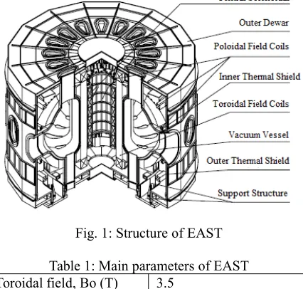
EAST is a full superconducting tokamak built by Institute of Plasma and Physics in China. Structure of EAST is shown as Fig. 1. The main height of EAST is 10m, while main diameter 7.6m and total weight 360 tons. The main parameter of the EAST are listed in Table 1.
Fig. 1: Structure of EAST
Table 1: Main parameters of EAST Toroidal field, Bo (T) 3.5
Plasma current, IP (MA) 1 Major radius, Ro (m) 1.7 Minor radius, a (m) 0.4
Aspect ratio, R/a 4.25
Elongation, Kx 1.6–2
Triangularity, dx 0.6–0.8
Vacuum vessel is a key component for EAST, which is field welded of 16 sectors into a torus. Each section has 1 horizontal port, 1 top vertical ports, 1 bottom vertical port and 2 supporting tubes attached to vertical ports. PFCs and their supports are installed on the inner wall[1-2]. The vacuum vessel provide an ultrahigh vacuum space
for plasma operation, while eddy current will flow on the vacuum vessel torus when plasma disruption event or VDE happens. The superconducting magnet system surround vacuum vessel consists of 16 toroidal field (TF) coils and 14 poloidal field (PF) coils. It provides high magnetic fields to confine plasma, which will also produce electromagnetic force on vacuum vessel and PFCs. The currents of PF coils and TF coils in steady-state are listed in Table 2.
Table 2: Currents of PF coils and TF coils in steady-state
Coil Turns Current per turn/kA
PF1,PF2 140 0.24
PF3,PF4 140 1.34
PF5,PF6 140 5.02
PF7,PF8 44 12.82
PF9,PF10 204 12.82
PF11,PF12 60 -7.59
PF13,PF14 60 -14.04
TF1-TF16 130 14.3
We are going to exploring a new way to analysis vacuum vessel with PFCs: doing electromagnetic analysis first to result the eddy current and electromagnet force, structure analysis followed with applying force as load. We believe we can get more accurate stress and strain results by this way.
THEORY THEORY THEORY
THEORY ANDANDANDAND VERIFICATIONVERIFICATIONVERIFICATIONVERIFICATION
The basic theory to calculate eddy current on vacuum vessel and PFCs is Maxwell equations. But we would like to use simplified equations to calculate. Eddy current on vacuum vessel is caused by the attenuation of plasma current. At first, we will limit plasma current to a attenuation function, and ignore the electromagnetic induction of eddy current to plasma current, just as what we will do in Ansys. Then we can solve Maxwell's equations in a simple form. In the space of vacuum vessel, we can deduce the equation below.
2 2 0 0 0
0
) (
t j t
j
j v v
v
∂ ∂ + ∂ ∂ = × ∇ × ∇
− µ ε
ρ µ
The meaning of each symbol and SI unit of measure are listed as Table 3.
Table 3: Definitions and units of symbols in above equation
Symbol Meaning SI unit of measure
jv vacuum vessel current density amperes per square meter
μ0 permeability of free space henries per meter
ρ0 electrical resistivity ohm per metres
t time second
ε0 permittivity of free space farads per meter
Now we are considering a simple vacuum vessel as one wall with a thickness of 8mm. The jvis simple as it
has only one component in this case. We disperse this vacuum vessel into 60 coils having the same axis with vacuum vessel, and eddy current flow along the discrete coils. Each coil has four parameters, current value I, z coordinate z, big circle radius r and circlet radius a. The coefficient of mutual inductance between coil i and coil j is Mi-j, which can be expressed by their parameters. The coefficient of self induction of each coil is Mi-i, which can also
be expressed by it's parameters. For coil i, we have equation below by treating plasma current as coil 0.
dt dI M dt dI M dt
dI M dt dI M I a
r
i i
i i
i i
i 0
0 60 60 2
2 1 1 2
0 ...
2
− −
−
− + + + +
This equation can be written into matrix form as below with plasma current expression and initial condition. dt dI M M M dt I I I d M M M M M M M M M I I I a r a r a r T 0 60 0 2 0 1 0 60 2 1 60 60 60 2 60 1 2 60 2 2 2 1 1 60 1 2 1 1 60 2 1 2 60 60 0 2 2 2 0 2 1 1 0 ... / ... ... ... ... ... ... ... ... ... / 2 ... / 2 / 2 ⎥ ⎥ ⎥ ⎥ ⎦ ⎤ ⎢ ⎢ ⎢ ⎢ ⎣ ⎡ + ⎥ ⎥ ⎥ ⎥ ⎦ ⎤ ⎢ ⎢ ⎢ ⎢ ⎣ ⎡ ⎥ ⎥ ⎥ ⎥ ⎦ ⎤ ⎢ ⎢ ⎢ ⎢ ⎣ ⎡ = ⎥ ⎥ ⎥ ⎥ ⎦ ⎤ ⎢ ⎢ ⎢ ⎢ ⎣ ⎡ ⎥ ⎥ ⎥ ⎥ ⎥ ⎦ ⎤ ⎢ ⎢ ⎢ ⎢ ⎢ ⎣ ⎡ − − − − − − − − − − − − ρ ρ ρ 003 . 0 / 6 0 10 t e
I = −
0 |t=0= i
I
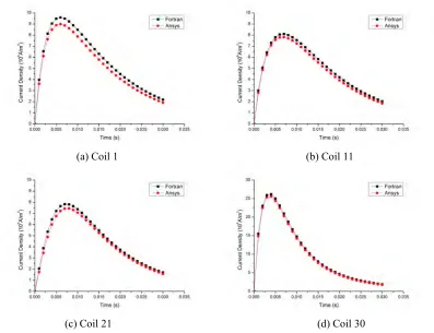
Now we can develop a programme in Fortran to solve this matrix equation to get the results of Ii. After
taking some simple calculation, current density of each coil can be gotten. This result will be used to verify another method to calculate eddy current using Ansys software.
In Ansys software calculation, we build a 1/16 circle model including single wall , plasma current and air. Solid97 element is used for them, while key option 1 should be set to 1 for vacuum vessel to open volt degree of freedom (DOF). Infin111 element is used to simulate far field boundary condition. Cpcyc APDL command is used to apply cycle symmetric condition. AY DOF in cylindrical coordinate system of axis should be constrained to 0 to insure magnetic flux parallel. Plasma current part is applied current density as load. First load step is a steady-state analysis to setup initial condition, while the second load step is a transient analysis with 300 substeps for end time 30ms.
Comparing two types of results in Fig. 2, one conclusion can be made: our eddy current calculation method using Ansys is right. Calculation for a complicate model will be done in the same way.
(a) Coil 1 (b) Coil 11
(c) Coil 21 (d) Coil 30
FINITE FINITE FINITE
FINITE MODELMODELMODELMODEL
1/16 section of the whole complicate model has been set up. It contains vacuum vessel, PFCs, PF coils, TF coils, air and infinite field. Vacuum vessel has two walls, one horizontal window, one upper vertical window and one down vertical window. PFCs contain latitude circles, support structures, high field plates, inner plates, dome plates, outer plates, passive plates and low field plates. PF coils have 14 big circles numbered from PF1 to PF14. TF coils have 16 D-shape coils for the whole model, one which is divided into two halves for each 1/16. The 1/16 section model is shown as Fig. 3.
PF1 PF3 PF5
PF6 PF4 PF2
PF8
PF10 PF9
PF7
PF11
PF13
PF14
PF12 Vacuum Vessel
TF
TF Plasma
Low Field Low Field Passive Plate Outer Plate Dome Plate
Passive Plate Outer Plate Dome Plate Inner Plate High Field Inner Plate
Fig. 3 Finite model of 3D transient electromagnetic analysis
Element type solid62, solid97 and infin111 are used. Infin111 is for infinite field modeling; solid62 is for vacuum vessel and PFCs modeling; solid97 is for all the others, PF coils, TF coils, plasma current and air. Solid62 is a electromagnetic-structure coupled element type, and it can be used for vacuum vessel with PFCs considering structure effect in electromagnetic analysis.
Boundary conditions and loads are nearly the same as the verification calculation before for MD working condition. The different between VDE and MD is that plasma current is moved vertical down depending on time. Eddy current distribution and time history are specially concerned of all the results.
E E E
ELECTROMAGNETICLECTROMAGNETICLECTROMAGNETICLECTROMAGNETIC ANALYSISANALYSISANALYSISANALYSIS
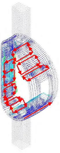
Fig. 4 is eddy current density vector plot at 5ms for MD. In fact, the direction of eddy current circle are invariant. We can see eddy current on the direction of big torus circle on vacuum vessel. There are also several local eddy current circles on PFCs because they are separate on big torus circle. We notice that the eddy current distribution on upper PFCs and down PFCs are symmetric on vertical middle plane. The eddy current density values on edges of local eddy current circles are significantly larger than those in the middle.
Fig. 5(a) shows time histories of eddy current density at 3 key points in MD. They obey a same rule: eddy current densitis rise quickly at the beginning to reach the peak value, then go down slowly. The time for peak eddy current density is about 10ms.
Eddy current distribution on vacuum vessel and PFCs in VDE is nearly the same as that in MD. Briefly, eddy current circles on vacuum vessel and PFCs can be shown also by Fig. 4. But the relative and absolute eddy current density values are quite different. So do the eddy current density time histories. Fig. 5(b) shows the time histories of eddy current density at 3 key points.
because of large moment.
Fig. 4 Eddy current density vector plot at 5ms for MD
(a) MD (b) VDE
Fig. 5: Eddy current density time histories at 3 key points in MD and VDE
S S S
STRUCTURETRUCTURETRUCTURETRUCTURE ANALYSISANALYSISANALYSISANALYSIS
Since element type solid62 is applied to vacuum vessel and PFCs, structure analysis is done with electromagnet analysis at once. In fact, indirect coupled analysis method can also be used to do structure analysis. After the electromagnetic analysis is done, node forces are in the result. Let Ansys leave electromagnetic analysis mode and enter structure analysis mode. Then, apply structure boundary condition, read node force load from database, and solve to finish a structure analysis.
(a) MD, 11ms (b) VDE, 5.5ms
Fig. 6: Stress contour of vacuum vessel and PFCs in MD and VDE
Due to the moment on the PFCs caused by local eddy current, high field plate is warped seriously. High stress appears at the roots of PFCs supports. So do the other PFCs. Although the maximum stress is unreal because of simplification of the supports, the stress on the PFCs is high enough to catch our attentions. We noticed that high field plates and inner plates can be destroyed more easily than other PFCs because of larger moments, especially inner plates. In latest plasma discharging experiment, one inner plate might be pulled out by this kind of moment. Some solution should be taken to avoid this type of accidents.
C C C
CONCLUSIONONCLUSIONONCLUSIONONCLUSION
Although vacuum vessel is safe, MD and VDE may destroy PFCs because of local eddy current. PFCs are pressed large node forces because the direction of local eddy current is perpendicular to toroidal field. Some operations such as connecting PFCs on the direction of big torus circle to form toroidal eddy current, enhancing PFCs supports may be useful to protect vacuum vessel.
REFERENCES REFERENCES REFERENCES REFERENCES
[1] D.M. Yao, Y.T. Song, S.T. Wu, Y.X. He, W.Y. Wu, S.J. Du, Design and structure analysis of the HT-7U vacuum vessel, Fusion Engineering and Design, Volumes 58-59, November 2001, Pages 839-843.
[2] Yun tao Song, Damao Yao, Songata Wu, Peide Weng, Structural analysis and manufacture for the vacuum vessel of experimental advanced superconducting tokamak (EAST) device, Fusion Engineering and Design, Volume 81, Issues 8-14, Proceedings of the Seventh International Symposium on Fusion Nuclear