18th International Conference on Structural Mechanics in Reactor Technology (SMiRT 18) Beijing, China, August 7-12, 2005 SMiRT18-J12-4
DYNAMIC BEHAVIOR AND FUNCTIONAL RELIABILITY OF WWER 1000
TURBINE FOUNDATION
Tsena Bozhanova Todorova*
Risk Engineering Ltd
34 Totleben Blvd., Sofia 1606, Bulgaria
Phone:+359 2 9515236/ext.202,
Fax:+359 2 9549100
E-mail: [email protected]
Marin Kostov Kostov
Risk Engineering Ltd
34 Totleben Blvd., Sofia 1606, Bulgaria
Velina Alexandrova Todorova
Risk Engineering Ltd
34 Totleben Blvd., Sofia 1606, Bulgaria
ABSTRACT
The presented paper shows a multidisciplinary study on the dynamic behaviour and functional reliability of WWER1000 turbine foundations built in NPP Kozloduy, Bulgaria.
The investigation consists of several interconnected parts: visual inspection of the turbine foundations, static analysis of the structure, analysis of the dynamic behavior of the structure based on finite element modeling, analysis of the structure deformations induced by different temperature regimes, analysis of the structure deformations based on the history of geodetic measurements, in-situ measurements of structure dynamic response due to turbine transients.
Based on the results of all those analyses conclusions are formulated concerning the bearing capacity and serviceability of the foundation structure. It was estimated that the most important loading that affect the dynamic behaviour of the structure is the temperature. Other important contributors for aging of the reinforced concrete structure are identified and their influence on the serviceability of the foundation structure is discussed. Measures for rehabilitation of the structure and improvement of the dynamic behaviour are proposed.
Keywords: turbine, foundation, dynamic analyses, cracks, temperature.
1. INTRODUCTION
The proposed paper reflects the main parts - the methodology and results, of a complex study on the dynamic behavior, serviceability and bearing capacity of 1000 MW turbine foundation at NPP “Kozloduy”. The study is provoked by problems during operation of the turbine, i.e. technological vibrations especially in transitional regimes and some doubts about low bearing capacity and increased deformability of the foundation structure. The purpose of the study is to establish the actual state of the structure, to recognize the main problems, to determine the reasons for their occurrence and to give recommendations for improvement.
2. DESCRIPTION OF THE STRUCTURE
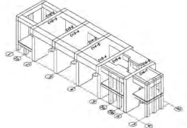
The turbine foundation is a complicated reinforced concrete consisting of bearing walls and frames. It is 86 m long, between 10 and 20 m wide and about 21.40 m high. The High pressured turbine is situated between the first and second transversal axis. The three Low pressure turbines are situated between the third, forth and fifth axis. The Generator is situated between the fifth and sixth axis and the Exciter – between the sixth and seventh transversal axis.
elements are cast in situ RC walls 1,5 meters thick and the RC columns, plates and girders are prefabricated. The RC walls are situated in axis 2 to 6. In axis 1 and 7 there are RC frames erected.
The main horizontal platform where the trust bearings of the turbine are located is erected at level +15,00.
The upper surface of the foundation mat is on level -2.60 m. The bottom surface of the mat reaches to level -6.40 m. Under the foundation plate is laid a concrete layer down to level -9.00 m. Under the concrete bedding ballast with thickness of about 2m is laid. The turbine foundation artificial bed reaches down a layer of dense sands.
Auxiliary RC plates are situated between the first and the second transversal axes on level +1.74, and the fifth and seventh axes on level +5.14.
Figure 1 shows a general view of the turbine foundation.
Fig.1 – General view of the turbine foundation
3. HISTORICAL REVIEW OF THE PROBLEM
The 1000 MW turbine is in operation since 1986. During the construction of the turbine foundation, after concreting of the transversal walls, vertical and inclined cracks were found. The cracks were analyzed and it was found out that they are most probably due to exothermic process in concrete. Repair was performed immediately with epoxy composite injection. After the repair of the walls and before the installation of the turbine unit a full scale dynamic testing was performed and the practical integrity of the foundation walls was proven.
In 1990 new dynamic tests were carried out. They showed qualitatively similar results with the previous tests. As a weak part of the turbine foundations were localized the frames at the first and the last structure axis. As a result of that analysis it was recommended to take engineering measures to change the dynamic behaviour, i.e to stiffen those areas or to introduce additional damping by installing dampers.
In the process of turbine operation have been observed high vibrations. In the maintenance there have been difficulties for shaft and aggregate adjustment, especially pronounced in the zone of the transverse walls in axis 2 and 5. During the regular maintenance of the turbine it was established also higher wear of some gaskets of the high and low-pressure turbines respectively, which were most probably due to increased vibrations and mass off-balance. During turbine starting higher temperature was registered in the zones of the thrust bearings at axis 2 and 3. Usually the structure needs 7-8 day for tempering.
In 2001 for the problems of the turbine operation a pilot study [9] was performed in order to show the current situation of the bearing structure and to develop a program for complex analyses. The investigation showed the presence of new cracks, some of them with considerable size. Most of the old injected cracks have opened again.
4. SCOPE AND STRUCTURE OF THE STUDY
The complex analysis of the structure condition and dynamic behavior of the turbine foundation is structured in four stages and the results of each stage are used as input information for the following stages.
In stage 1 is established the actual status of the structure of the turbine foundation. The cracks in the main bearing elements are mapped (width, depth and length); the actual values of the strength and dynamic characteristics of the materials (concrete and steel) are established. The obtained field data and the conclusions which were drown are used in the next stage for numerical analyses of the dynamic structure behavior. A program for long-term investigations of foundation status and the monitoring in order to increase safety is developed.
In stage 2 full scale dynamic tests in normal operation and in transition regimes, dynamic and static analysis of the turbine foundation structure are performed. The main goal of the analysis is to estimate the stresses and deformations in all structural elements due to static and dynamic loads. For the analyses a FEM model updated with results from stage 1 is used. The analytical study consists of three types of numerical analysis:
Modal analysis – to define the natural frequencies and modes of the structure. They are used to define the resonant frequencies of the structure.
Dynamic analysis with harmonyc input excitation – to define the theoretical values of the vibration amplitudes at the thrust bearings. As an input excitation sinusoidal signals with frequencies equal to the resonant ones are used. The analytically obtained results are compared with the in-situ measured results.
Static analysis – to define the deformation of the structure due to temperature loads in normal operation; to determine the stresses and the internal forces in main bearing structure elements in order to perform capacity checks. A quasystatic approach is applied for internal forces due to the seismic excitations. Calculated static displacements are compared with data from geodetic monitoring, carried out during the whole operation period of the turbine.
In stage 3, based on the conclusions from stages 1 and 2, is prepared conceptual design for: 1) structure rehabilitation; 2) monitoring of the bearing structure; 3) improvement of geodetic monitoring; 4) measures for reduction of vibrations.
In stage 4 is planned for technical design of the measures resulting from step 3.
5. AS BUILT STATUS OF THE TURBINE FOUNDATION
To establish the actual status of the foundation in situ and laboratory tests are made according to the plans of stage 1. Based on the test results and the observations conclusions for the actual status are drown and preliminary analysis for the reasons for the observed defects is made.
5.1. Performed tests
In situ tests
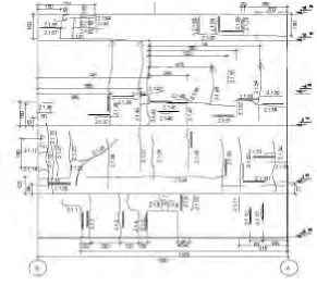
Mapping of all available cracks, including those, which appeared immediately after concreting of the foundation. On Fig. 2 is shown a typical picture of cracking of the transverse walls. For all cracks is measured width and length and for about 40% of them depth of crack is measured as well.
Supersonic diagnostic – using supersonic testing is established the density of concrete and are defined the zones in which the elastic modulus of concrete is reduced because of cracking or/and due to bad quality of concrete.
Electromagnetic diagnostics of reinforcement – the thickness of the concrete cover is defined as well as the diameter of the reinforcement bars and their location in the structure element. For control of results at some places samples of uncovered reinforcement are taken.
Not destructive methods for testing of concrete (hammering) are used and in some places.
Laboratory tests
Fig. 2 – Wall on axis 2 – map of the cracks
5.2. Findings for the actual state of the turbine foundation
The investigations of the turbine foundation established that: the general state of the turbine foundation is good;
the structure concrete is generally of good quality and with good strength parameters. In the laboratory tests starting process of reinforcement corrosion is estimated as well as initial carbonization of the concrete. Both processes are influenced and activated by the existing cracking.
the measured values of the propagation velocity of the supersonic waves show decreased density (and respectively reduced E-modulus) in some areas. These findings were taken into account in stage 2 - static and dynamic analysis.
most of the cracks are about 0.1 – 0.25 mm wide and not more than 100mm deep. The existing cracking should not affect the dynamic and static behaviour of the foundation
The main conclusion from the tests of the foundation in stage 1 is that the most probable reason for the cracking is the temperature. This conclusion is based mainly on the observed positioning of the cracks and the depth of penetration. The intensive crack mapping of all surfaces is supporting this conclusion. The temperature distribution in the foundation structure, in the moment of concreting and concrete hardening, and during normal operation, is similar and lead to similar deformation in the structure. Therefore the old epoxy injected cracks open again and there is still development of new cracks. The main cracks are some kind of work joints, which allow the turbine foundation to expand and shrink and prevent the appearance of unfavorable structure stress fields. This is also confirmed by the fact that the more deformable parts of the construction are less cracked. Nevertheless the cracks should be repaired in a way that allows from the one side them to function as work joints and from the other side prevents the structure deterioration due to corrosion and carbonization. In the same time it is not necessary to recover the structure stiffness because the temperature processes in the foundation will lead to new opening and there is sufficient structure capacity (as estimated in stage 2).
6. DYNAMIC TESTING OF THE TURBINE FOUNDATION
The dynamic testing is performed on foundation in two operation regimes – in cold state of the turbine during starting, and in tempered state - when the turbine has worked for about 2 months. The kinematical parameter of the vibrations registered during the measurements is acceleration. By integrating of the records are obtained also velocigrams and seismograms.
During the measurements in none of the measurement points were observed values of the displacements and velocities exceeding the code limits. Also the sanitary norms for turbine foundation are satisfied.
During the transitional regimes of starting and stopping of the turbine, the construction passes relatively fast through the resonance frequencies between 10Hz and 25Hz without unfavorable increasing of the vibrations. Up to 600 rev/min (10Hz), because of the small values of dynamic forces, the registered response is insignificant.
7. ANALYTICAL STUDY OF THE TURBINE FOUNDATION 7.1. Purpose of the analysis
The main goals of the analysis are to define analytically:
-Natural frequencies and modes of vibration of the structure;
-Deformations in critical points due to static, dynamic and temperature loads; -Stresses in critical elements of the structure, to be used for capacity assessment;
-Response amplitudes due to forced vibration of the foundation during different regimes of turbine operation;
A 3D FEM of the turbine foundation is generated for that purpose.
7.2. Modeling of the foundation structure 7.2.1. Generated models
Two 3D models are generated. The first one consists of solid elements. It is developed using FEMAP preprocessor and is analyzed with the program STARDYNE. The model consists of 919 solid elements, 61 mass elements and 1719 nodes each with three DOF. The aim of that model is to study the general dynamic behaviour and soil structure interaction as well as to create a reference for quality assurance purposes. The general view of the model is shown on Fig.3.
Fig.3 – General view of the first model generated by solid elements
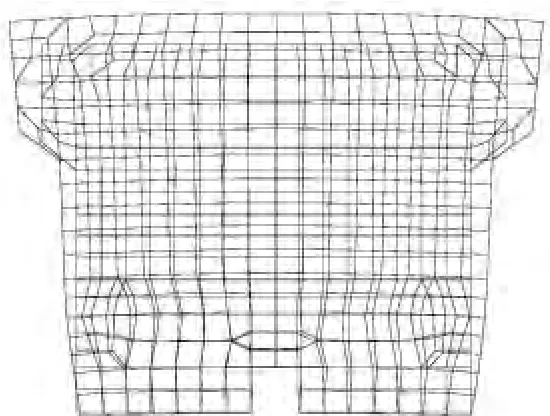
The second model is a refined 3D model with beam and plate elements. The modeling and analysis of this model is performed with software system STAAD ІІІ 23W. The model consist of 4056 nodes, 362 beam elements and 3741 plate elements. The beam elements are with 6 DOF in each node, and the plate ones – 5 DOF. The aim of the model is to study the stress and strain distribution within the structural elements. The general view of the second model is shown on Fig.4
Fig.4 – General view of the second model generated by beam and plate elements
7.2.2. Modeling of the soil-structure interaction
To estimate the correct behavior of the structure of the turbine foundation during dynamic loads – operation of the turbine and seismic excitation it is necessary to take into account the influence of the of ground base. The soil structure interaction is modeled by adding of three dimensional springs and dashpots to the foundation mat. The value of the spring stiffness depends on characteristics of soil strata [8], dimensions of the turbine foundation mat and on the character of the dynamic load.
For normal operation dynamic loads the soil strain is small and the soil media can be considered elastic. Under seismic excitation, because of the larger soil strains, the soil modules are degraded and damping is increased. The stiffness of the springs in the seismic case are up to three times lower than those used for evaluation of dynamic vibrations in normal operation [7].
7.2.3. Modeling of the mechanical part
For the purposes of the dynamic analysis the turbine components are modeled by system of lump masses, located on the level of the turbine shaft – elevation 16.80 and connected with rigid elements with the bearing elements. In this way additional torsion and bending moments, caused by inertia forces, are considered.
7.2.4. Characteristics of materials
The material characteristics of the turbine foundation are based on results from stage 1. The stress analysis is made with the actual characteristic of the concrete and the reinforcement. Decreasing of elastic modules proportionally to the supersonic wave velocity reflects the influence of the structural cracking.
7.3. Loads
7.3.1. Static loads
The static loads include dead weight, loads from equipment and steel platforms and from condensers. The loads from the supported by the turbine foundation pipelines are modeled as uniformly distributed. The torsion excitation due to short-circuit is modeled as a force pair, acting on the stator support.
7.3.2. Dynamic normal operation loads
The dynamic force in transverse direction due to off-balance masses is defined according to the requirements of the Bulgarian code for turbine foundations [3], [4] and also considering the rotor weight. The loads are applied at the supports of the turbine rotor. The dynamic horizontal load in longitudinal direction is supposed to be 0.5 from the dynamic horizontal load in transversal direction. For the strength capacity assessment quasystatic loads replace the operational dynamic loads.
7.3.3 Temperature loads
During turbine operation the foundation temperature is irregularly distributed - the parts placed near the thrust bearings are heated more than the parts placed nearer to the foundation mat. To determine the maximal deformations and stresses due to the temperature loads two cases are considered– tempered state - when the turbine is in normal operation and cold state – when the turbine is stopped.
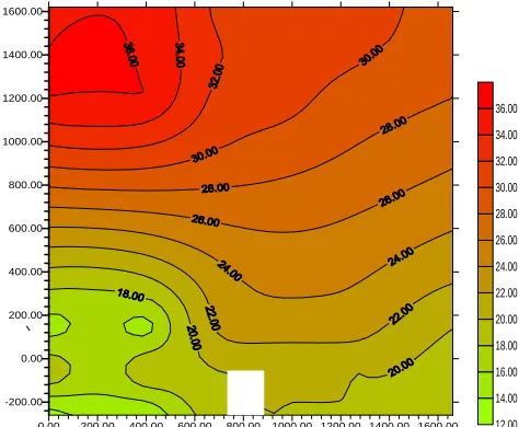
To define the tempered case, in-situ multiple measurements of temperature of the air and the concrete were conducted. The basic temperature of the turbine foundation elements is 20◦C. On Fig. 5 a graphic illustration of the temperature distribution at a support wall is shown.
0.00 200.00 400.00 600.00 800.00 1000.00 1200.00 1400.00 1600.00 -200.00 0.00 200.00 400.00 600.00 800.00 1000.00 1200.00 1400.00 1600.00 12.00 14.00 16.00 18.00 20.00 22.00 24.00 26.00 28.00 30.00 32.00 34.00 36.00
Fig. 5 Temperature field at the wall on axis 2, turbine normal operation
For the cold case is assumed that the foundation temperature changes gradually from +25 C at elevation +15.00 downwards to a temperature of +20 C. Elements with lower than +20 C temperature are assumed that they do not change.
7.3.4. Seismic loads
The seismic excitation is described by acceleration response spectrum on free field for the NPP Kozloduy site. The parameters of the seismic excitation for OBE are as follows:
Maximal absolute horizontal acceleration – 0.1 g Maximal absolute vertical acceleration – 0.05 g Maximal spectral horizontal acceleration – 0.23 g Maximal spectral vertical acceleration – 0.115 g
The seismic design forces in structure elements are calculated with spectral method and SRSS combination of modal forces.
7.3.5 Load combinations
For the structure capacity assessment normal operation loads and combinations with seismic and accident loads are considered. In normal operation load combination the effects caused by dead weight, normal operation dynamic loads, and temperature are considered [2].
The abnormal load combinations consider effects caused by gravity loads, dynamic operational loads in horizontal direction, seismic loads and load due to short-circuit [2].
7.4 Model verification
Because there is good coincidence between analytical and experimental results (as it will be shown below) we believe that the analytically obtained results describe correctly the behavior of the turbine foundation exposed to dynamic and static loads.
8. ANALYSIS RESULT
8.1. Static analysis
The static analysis is performed to assess stresses and deformations due to combined action of gravity loads, dynamic normal operation loads (according to the turbine technical specification), loads from auxiliary equipment, temperature loads, load due to short-circuit and seismic loads.
The results from the static analysis show that all structure elements of the turbine foundation have sufficient capacity.
8.2. Modal analysis
The natural frequencies and modes are determined by modal analysis. It is estimated that the second model generated with beam and plate elements is providing closer results to the measured response of the real structure. The model is calibrated in several test calculations by adjusting the concrete E-modulus and the soil spring stiffness.
The analysis of the natural modes of vibration shows the following features of the dynamic behavior of the turbine foundation:
The first mode of vibrations is characterized by predominantly longitudinal response at 2,5 Hz, i.e. the stiffness of the structure in longitudinal direction is lower than in transverse direction. The first mode of vibrations of the turbine foundation is shown in Fig.6.
The 2th, 3th and 4th modes are at frequencies from 4 to 7.3 Hz. They show predominantly rotation of the structure around a vertical axis (the thrust bearings placed in axis 2, 3, 4, 5 and 6 are not affected). There are large modal displacements in transversal direction at the edge axes 1 and 7 (stronger in axis 1 at 4.37Hz). The natural frequency 4.37 Hz is an important one especially for the longitudinal response of the thrust bearings in axes 2 and 4. This characteristic mode shape is mainly due to the frames in axis 1 and 7 that are with comparatively small stiffness in comparison to the walls.
The natural frequency of the first vertical mode is 11.58 Hz.
Near to the operation frequency of the turbine, i.e. between 24 and 26 Hz, there are modes with predominantly vertical response in axis 1, 3, 7 and some response in longitudinal direction in axis 2, 3, 4, 6. Some minor longitudinal response is obtained also at the auxiliary structures at elevation +5.40. Based on the modal analysis of the turbine foundation the expected resonant frequencies can be summarized as follows:
In transverse directions:
At axis 1: 4.4 Hz, about 8.5 Hz and 14 Hz
At axis 2, 3, 4, 5 and 6: 9 Hz, 11 Hz and about 15 Hz At axis 7: 4.4 Hz, about 15Hz and 18.5 Hz
In longitudinal direction:
Low frequencies between 2.5 and 4.5 Hz
For the supports on axis 3 and 4 – between 7 and 9 Hz
For all thrust bearings supports between 18 and 20 Hz and for axis 2, 3, 4, 5 and 6 – 24.5 Hz In vertical direction:
For all bearing’s supports – 12 Hz and 16.85 Hz For the bearings on axis 1, 2, 5, 6 and 7 – 13.85 Hz For the bearings on axis 1, 3 and 7 – 24.5 Hz
8.3. Comparison between analytical and experimental results
The measured resonant frequencies of the turbine foundation structure are taken from the power spectral density function of measured accelerations due to ambient vibration (turbine is not operating). Comparing the results from the noise measurement with the analytically obtained natural frequencies we have found that there is good coincidence:
are pointed out the frequencies of 4, 8.5 and 14 Hz, which are the same as those defined by modal analysis. At the thrust bearings on the walls on axis 2, 3 and 4 coincidence between experimental an analytical results is observed for frequencies 9, 11 and 14 Hz. At the thrust bearings on walls on axis 5 and 6 the resonant frequency which coincidences is 9 Hz. At axis 7 there is coincidence of resonant frequencies at 4 and 18.5 Hz.
In longitudinal direction the analytically defined frequencies coincide with the experimentally measured ones at 4.5 Hz and between 18 and 20 Hz.
In vertical direction there is a coincidence at 12 Hz and about 21 Hz.
Fig.6 – First mode of vibration (2,5 Hz)
8.4. Forced vibrations due to harmonic excitation
The aim of the harmonic analysis is to estimate the vibration amplitudes of the thrust bearings in transverse and in vertical direction in different regimes of turbine operation. Further on the obtained values are compared with the allowable code values and with the results from the dynamic tests.
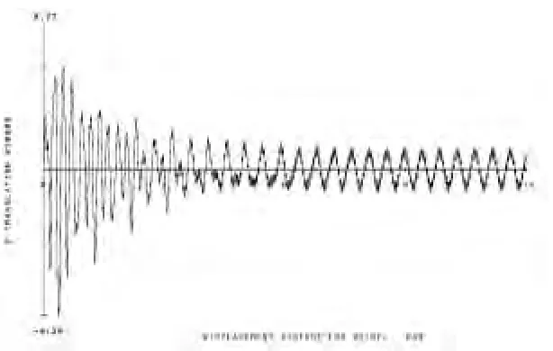
As a result of the analysis a vibration time history graphic is obtained for some important structure locations. The graphic shows three main phases of the calculated response – impulse loading, response decay and steady state. The computational duration of the analysis is 12 seconds. Material damping 2% of the critical is used for transverse vibrations and 5% - for vertical vibrations. The higher value of damping in the vertical direction is based on the soil-structure interaction.
The three phases in the response are due to computational effect caused by the sudden application of the harmonic excitation to the model. The first phase with high amplitude of vibrations is due to the impulse action of the forces applied. The second phase – in which the response decays, attenuates to a steady state phase (the natural vibrations are damped) and the third phase is stationary response (mainly the forced vibrations). In normal operation the foundation behaves close to the stationary phase. All operation disturbances cause a change in the stationary regime and provoke an excitation of the natural modes of vibration. They are added to the forced vibrations and the regime becomes closer to first or the second phase of the calculated response.
In order to analyze the longitudinal vibrations are investigated cases of harmonic excitation with phase difference in each thrust bearing. The longitudinal vibrations could be excited by steam vibration or by the longitudinal component of a harmonic force caused by out-of-plain rotation.
In accordance with the performed dynamic tests two cases of harmonic excitation in transversal direction are considered – with frequency of harmonic excitation 12 Hz (720 rev/min) and with frequency 19.5 Hz (1170 rev/min). In the vertical direction, excitation with frequency of 12 Hz is considered (720 rev/min). It corresponds to the 11th mode of vibration, where strong response in vertical direction in axis 1 and 7 is expected.
In the regime of normal operation an excitation with frequency of 25 Hz – 1500 rev/min in transverse and vertical direction is considered.
8.4.1. Vibration analysis in regime of turbine turning on/off
of harmonic excitation changes from 0 to 25 Hz. When the excitation frequency is equal to the natural frequencies of the turbine foundation it is possible to appear a resonance, i.e. the vibration amplitudes shall quickly increase.
The analysis includes calculation of the forced vibration amplitudes and comparison between analytically obtained and recorded data respectively. During the tests the revolutions of the turbine were steadily increasing, and the natural vibrations may not have been damped. From the analytical results it can be seen that the natural vibrations attenuate for about 2 s at places on the walls and for about 5 s for places on frames, i.e. axes 1 and 7. Having in mind the slow change of the revolutions it can be assumed that the measured amplitudes are amplitudes of the forced vibrations. Better coincidence between analytical and measured values is obtained at nodes placed on the walls where the natural vibrations attenuate faster. For the values measured on the edge axes, especially with 19 Hz can be assumed that the natural vibrations are not fully attenuated.
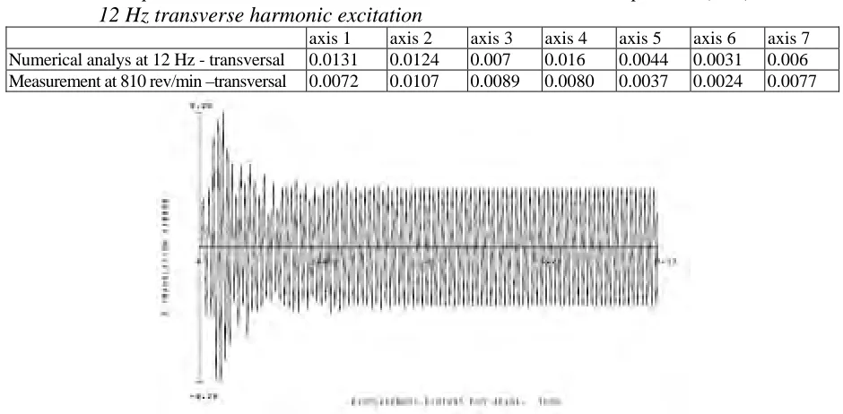
Comparisons of results from dynamic analysis and measurements in the transitional regimes of the turbine are illustrated on figures 7 and 8 and tables 1, 2 and 3.
Table 1 – Comparison between calculated and measured horizontal amplitudes (mm),
12 Hz transverse harmonic excitation
axis 1 axis 2 axis 3 axis 4 axis 5 axis 6 axis 7 Numerical analys at 12 Hz - transversal 0.0131 0.0124 0.007 0.016 0.0044 0.0031 0.006 Measurement at 810 rev/min –transversal 0.0072 0.0107 0.0089 0.0080 0.0037 0.0024 0.0077
Fig. 7 – Horizontal vibrations in transverse direction at axis 2 – 12 Hz transversal excitation of thrust
bearing.
Fig. 8 – Horizontal vibrations in transverse direction at axis 7 - 12 Hz transversal excitation of thrust
bearing
to 720 rev/min and the slower attenuation of the natural vibrations at the frames.
Table 2 – Comparison between calculated horizontal amplitudes (mm) and measured ones,
19.5 Hz transverse harmonic exitation
axis 1 axis 2 axis 3 axis 4 axis 5 Axis 6 axis 7 Numerical analys at 19.5 Hz-transversal 0.003 0.009 0.009 0.015 0.0067 0.0075 0.004 Measurement at 1140 rev/min –transversal 0.0105 0.0098 0.0083 0.0085 0.0049 0.0062 0.0087
Table 3 – Comparison between calculated and measured vertical amplitudes (mm),
12.0 Hz harmonic exitation
axis 1 axis 2 axis 3 axis 4 axis 5 axis 6 axis 7 Numerical analys at 12 Hz 0.004 0.0031 0.0023 0.0024 0.0043 0.0069
Measurement at 810 rev/min 0.0047
The results in Tables 2 and 3 show good coincidence between calculated results and measured values in axes 2, 3, 4, 5, and 6. The differences between measured and analytical values can be explained with the superposition of the natural vibrations.
8.4.2. Vibration analysis for normal turbine operation
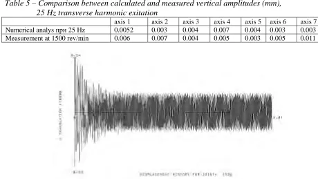
The turbine normally operates at 1500rev/min. The dynamic excitation is applied as sine curve with frequency of 25 Hz. The results from the analysis and measurements are given in Tables 4 and 5 and figures 9 and 10.
Table 4 – Comparison between calculated and measured horizontal amplitudes (mm),
25 Hz transverse harmonic exitation
axis 1 axis 2 axis 3 axis 4 axis 5 axis 6 axis 7 Numerical analys at 25 Hz 0.011 0.007 0.006 0.009 0.01 0.0084 0.006 Measurement at 1500 rev/min 0.014 0.007 0.005 0.006 0.016 0.025 0.028
Table 5 – Comparison between calculated and measured vertical amplitudes (mm),
25 Hz transverse harmonic exitation
axis 1 axis 2 axis 3 axis 4 axis 5 axis 6 axis 7 Numerical analys при25 Hz 0.0052 0.003 0.004 0.007 0.004 0.003 0.003 Measurement at 1500 rev/min 0.006 0.007 0.004 0.005 0.003 0.005 0.011
Fig. 10 – Horizontal vibrations in transverse direction on axis 7 - 25 Hz transversal excitation
on the thrust bearing
The comparison between analytical and measured results shows that:
The analytically determined amplitudes do not differ significantly from the measured ones in axes 1 to 5. There is some exception for axis 6.
The big difference between the analytical results and test is in axis 7 – thrust bearings of the exciter. Here the measured values differ almost 2 times from the analytical ones.
From one hand the stiffness of the frame in axis 1 is smaller than the stiffness of the frame in axis 7 from the other hand the dynamic load due to the rotating mass in axis 7, which is about 8% of the dynamic load of the middle supports, is almost 2 time smaller than the load in axis 1 thus theoretically it cannot be expected the vibration on axis 7 to be bigger than the one on axis 1. The measured higher values of the vibrations on axis 7 are probably due to local effects, which provoke natural vibrations, which on the end axis attenuate slower in comparison to the vibrations on axes 2 to 6. So in that case the measured amplitudes are superposed forced vibrations and natural vibrations. This may explain also the relatively high values of vibration in longitudinal direction.
The dynamic tests have registered vibrations in longitudinal direction. Centrifugal dynamic forces act in transverse and in vertical direction. The reasons for the appearance of vibrations in longitudinal direction are complex and can be due to following:
Impulse action of the steam on the blades Pulsations of the steam stream
Turbine shaft vibration
Out of plane rotation due to differential temperature High level of ambient vibration
Non-stationary excitation that excite longitudinal natural modes
8.4.3. Static analysis and temperature
Based on the calibrated models are studied the deformations of the turbine foundation in two states – normal operation and outage.
The analysis in the case of turbine operation shows that structure deformations appear mainly due to differential heating and operation loads.
The case of “turbine in outage” is the one when the geodetic measurements usually take place and also the adjustment of the turbine is made.
Fig. 11 – Deformation of the wall in axis 2 due to temperature
Table 6 – Displacements (cm) at the nodes of the thrust bearings due to temperature only
axis 1 2 3 4
node 6 9 12 1526 1536 1517 659 669 650 1010 1020 1001 X -0,55 -0,567 -0,585 -0,39 -0,406 -0,38 -0,25 -0,23 -0,21 -0,08 -0,06 -0,04 Y 0,084 0,170 0,1491 0,142 0,163 0,08 0,064 0,135 0,084 0,205 0,169 0,068 Z 0,126 0,0123 -0,154 -0,17 0,0177 0,188 -0,17 -0,01 0,13 -0,09 0,057 0,196
node 2343 2497 2641 645 640 2787 642 649 641 X 0,132 0,153 0,09 0,24 77 0,288 0,2 39 0,4 70 0,386 0,362 Y 0390, 0,07 0,10 6 -0,04 -0,0 42 0,022 -0 8,0 -0,08 -0,08 Z 0,156 -0,11 0,03 1 0,111 -0,1 010, 1 -0 3,0 0,04 0,1
axis 5 6 7
The results show that:
The temperature is a very significant factor for structure deformations;
The biggest deformations are those in longitudinal direction (axis X); big values are obtained at thrust bearings placed in axes 1, 2 and 3. In vertical direction the biggest deformations are in axes 1, 2, 3 and 4. In transverse direction the bearings supports practically do not move due to temperature effects. Big deformations suffer the edges of the structure.
Analyzing the deformed scheme of the foundations, it appears that the fundament “spreads” to the left and to the right, and the deformations of the first axes is larger than those on axes 5, 6 and 7. In vertical direction the foundation mat is declined to the right (Reactor department).
When the foundation is loaded only with temperature loads there is lowering of axes 1 and 7 and rising of axes 3 and 4.
In transversal direction for all axes there is “spreading” to the left and to the right from the thrust bearings supports, it is most strongly expressed in axes 1, 2, 3 and 4 (frames).
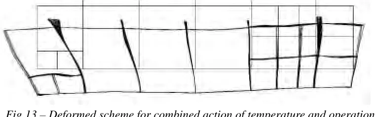
The analysis of the geodetic measurements performed since commissioning of the plant supports the picture of analytically obtained deformations. On the foundation mat clearly is shown the tendency for declination of the fundament to the right (Reactor building) and upward movement of axis 7 (Fig. 13). The rising of the foundation slab on axis 4, established in almost all geodetic measurements was confirmed with the temperature analysis. The “shrinking” of columns in axis 7 caused by vertical deformations from elevation +15.00 is established by analysis geodetic measurements too.
Fig.13 – Deformed scheme for combined action of temperature and operation loads
9. CONCLUSIONS
From the accomplished analyses following conclusions could be formulated: The structure of the turbine foundation is in good condition
The turbine foundation structure has sufficient bearing capacity to resist the forces due to static and dynamic loads resulting from turbine operation and seismic excitation.
The dynamic behaviour of the turbine foundation is very good and the observed vibrations do not exceed the code limit values.
The cracking is caused by temperature influences.
The temperature deformations of the foundation can disturb the turbine normal operation.
The temperature influence and the cracking of the walls should be controlled by proper engineering measures for improved cooling and ventilation of the turbine foundation structure and the turbine hall as a whole. The proper tempering of the foundation is especially important for the period of adjustments and for the start-up.
The cracking of the concrete walls should be treated in a dual way, i.e. cracks are preventing overstressing of the structure in case of unfavorable temperature loading but they deteriorate significantly the structure capacity by intensive aging rate of concrete and reinforcement. The rehabilitation treatment should close the cracks in order to prevent further development of aging processes and in the same time should give possibilities for temperature expansion.
AKNOWLEDGEMENTS
This work was performed under contract with Kozloduy NPP and their support is deeply acknowledged. The authors also wish to thank Mr. O.Ganchev for his contribution to organize and perform the test measurements.
REFERENCES
[1] Risk engineering Ltd, (2003) “Technical project for vibration analyses of turbine foundations 9 and 10, Kozloduy NPP”
[2] (1989), Norms for loads and affects on buildings and equipment, BSA [3] (1966) Guidelines for turbine foundation design, BSA
[4] (1986) Norms for design of foundation under dynamic loads, generated by machines, BSA [5] Т. Germanov , (1999), Soil mechanic, “Technika”, Sofia
[6] UASG, (2001), Report for measurement and analysis of turbine substructure vibrations, Unit 5 of KNPP [7] ASCE Standard, Seismic Analysis of Safety-Related Nuclear Structures and Commentary on Standard for Seismic Analysis of Safety related Nuclear Structures, 1986