Available online at www.ijrat.org
A Simulation Study Of Vibrational Analysis Of
T-Section Cantilever Beam
G. Sree Bhavani Charan
1, Dr.G.Naga Malleswara Rao
21
B.Tech student, Dept. of Mechanical Engineering, G. Pulla Reddy Engineering College, Kurnool, India
2Professor of Mechanical Engineering, Eswar College of Engineering, Narasaraopet, India.
Abstract: Beams are generally used in structural members like bridges etc. There are several types of beams such as T, I, HSS, L available to meet industrial and domestic applications. The major problems and failures with beams are fatigue failures, vibrations and improper analysis of various properties. This work discusses the effects of vibration on T-section structural steel cantilever beam as they can alter many parameters like shape, stiffness etc., and also the modes of frequencies. To avoid these ill effects, a complete vibrational analysis is very essential. Thus, in this proposed work, an attempt has been made to analyze such members by using ANSYS by providing several free end conditions and also to find the natural frequencies and validating the result with finite element analysis of the beam. It is also proposed to carry out this work to analyze the T-section with different materials such as Mild Steel, Structural Steel and Aluminum.
Keywords: Vibrational Analysis, ANSYS, free end conditions, natural frequencies, finite element analysis
1. INTRODUCTION:
A cantilever is a rigid structural element, such as a beam or a plate, anchored at one end to a (usually vertical) support from which it protrudes; this connection could as be perpendicular to a flat, vertical surface such as a wall. Cantilevers can also be constructed with trusses or slabs. When subjected to a structural load, the cantilever carries the load to the support where it is forced against by a moment and shear stress. Cantilever construction allows overhanging structures without external bracing, in contrast to constructions supported at both ends with loads applied between the supports, such as a simply supported beam found in a post and lintel system. Cantilevers are widely found in construction, notably in cantilever bridges and balconies. In cantilever bridges, the cantilevers are usually built as pairs, with each cantilever used to support one end of a central section.
2. VIBRATIONS:
Any motion which repeats itself after an interval of time is called vibration or oscillation. All the bodies having mass and elasticity are capable of vibration. The mass is inherent of the body and elasticity causes relative motion among its parts. All the vibrations are due to internal elastic forces within the body. Whenever the body is displaced from its equilibrium position by external force, work is done by external force in producing the initial displacement against internal elastic forces which resist deformation. This work is stored as strain energy. If external force is removed and body is released, the internal elastic forces tend to restore the body to its equilibrium position.
3. HISTORICAL BACKGROUND OF ANSYS:
The finite element method of structural analysis was created by academic and industrial researchers during the 1950s and 1960s.The underlying theory is over 100 years old, and was the basis for pen-and-paper calculations in the evaluation of suspension bridges and steam boilers. ANSYS is a complete FEA software package used by engineers worldwide in virtually all fields of engineering:
Structural Thermal
Fluid (CFD, Acoustics, and other fluid analyses)
Low- and High-Frequency Electromagnetics
A partial list of industries in which ANSYS is used:
Aerospace - Electronics & Appliances Automotive- Heavy Equipment & Machinery
Biomedical - MEMS - Micro Electromechanical Systems
Bridges & Buildings -Sporting Goods There are three main component products derived from ANSYS Multi physics:
ANSYS Mechanical – structural & thermal capabilities
ANSYS Emag – Electromagnetics ANSYS FLOTRAN – CFD capabilities ANSYS Design Space – linear structural and steady-state thermal analyses, a subset of ANSYS Mechanical capabilities in the Workbench Environment.
Available online at www.ijrat.org
machine component while it is being designed. It isthe most fundamental of all dynamic analysis types and is generally the Dynamic Design analysis method the modal expansion can be performed after the spectrum analysis, based on the significance factor SIGNIF on the MXPAND command.
Vibration Analysis is used to detect early precursors to machine failure, allowing machinery to be repaired or replaced before an expensive failure occurs.
Vibration analysis is a very wide and complex domain which exploits several aspects of the testing and diagnosis disciplines from condition monitoring to defect detection. Improvements in sensor technology now permit the use of vibration analysis methodology within the micro/ meso also.
4. OBJECTIVES OF THIS STUDY:
In this work, it is proposed to carry out the vibrational analysis on T-Section by using varying materials viz., Mild Steel, Structural Steel, and Aluminium with the help of ANSYS and the comparison of the natural frequencies has been compared.
5. METHODOLOGY:
Modal analysis of cantilever beam is used to determine the natural frequencies and mode shapes, which are important parameters in the design of a structure for dynamic loading conditions. They also required for spectrum analysis or for a mode superposition harmonic transient analysis
5.1. Beam Model and its Specifications
In the present case cantilever beam of length 2000 mm is considered. One end of the beam is fixed and the system is subjected to vibration.
5.2. Beam Specifications
TABLE 1: Dimensions and Properties of a Cantilever Beam
Dimensions/ Properties Structural Steel Mild Steel Aluminium
Length (mm) 2000 2000 2000
Width(mm) 300 300 300
Flange Thickness (mm) 175 175 175
Web Thickness (mm) 300 300 300
Height (mm) 800 800 800
Young’s Modulus (MPa) 2x10⁵ 2.068x10⁵ 0.69x10⁵
Density( Kg/m3) 7850 8000 2700
5.3.Modal Analysis with ANSYS Workbench R-15
The modal analysis for the cantilever beam is executed by ANSYS Workbench
Available online at www.ijrat.org
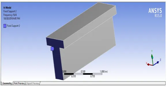
5.4. Geometry
First geometry of beam is created using Design Modeler.
[image:3.595.172.410.109.272.2]
Fig. 2: Geometry
5.5.
5.6.Generate Mesh
Mesh on the beam is generated automatically by ANSYS. SOLID186 element is used. The element is defined by 20 nodes while
each node has three degrees of freedom. The SOLID186 has quadratic displacement behaviour. The size of the element is 2 mm
[image:3.595.128.427.375.531.2].
Fig.3: Meshing of Beam
5.7.
5.8.Apply Boundary Conditions
The materials properties are assigned to the beam all degrees of freedom on surface are
taken. They are denoted with the blue flag Figure 4. This condition prevents the movement of the
surface in a space
.
[image:3.595.126.416.619.773.2]Available online at www.ijrat.org
5.9.Solution
The type of solver and the solution method in program ANSYS is selected automatically. For this modal analysis the direct solver including the block Lanczos method is used.
6. RESULTS AND DISCUSSIONS
6.1. Modal Analysis of Cantilever Beam
The modelling of beam and the analysis are carried out using ANSYSWORKBENCH R15 as per above procedure.
The results obtained are given as below based on the type of material used.
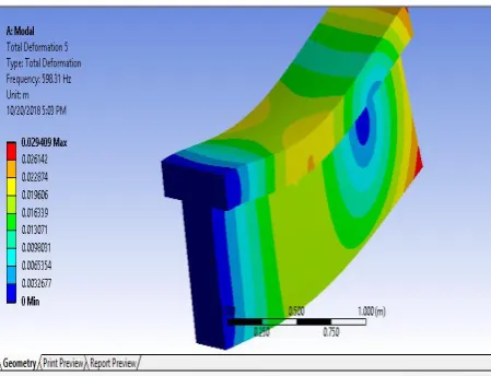
6.2.Mode Shapes of Structural Steel
[image:4.595.308.539.188.364.2]
Fig. 5: First Frequency and Mode Shape Fig. 6:Second Frequency and Mode Shape
[image:4.595.71.296.585.757.2][image:4.595.320.550.587.755.2]
Fig.7: Third Frequency and Mode Shape Fig.8: Fourth Frequency and Mode Shape
Available online at www.ijrat.org
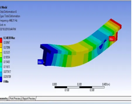
[image:5.595.71.543.103.303.2] [image:5.595.317.541.334.517.2]6.3. Mode Shapes of Mild Steel
Fig. 13: Third Frequency and Mode Shape Fig. 14:Fourth Frequency and Mode Shape
[image:5.595.66.289.336.526.2]
Fig. 15: Fifth Frequency and Mode Shape Fig. 16: Sixth Frequency and Mode Shape Fig. 11:First Frequency and Mode Shape
[image:5.595.318.541.550.728.2][image:5.595.64.292.556.734.2]
Available online at www.ijrat.org
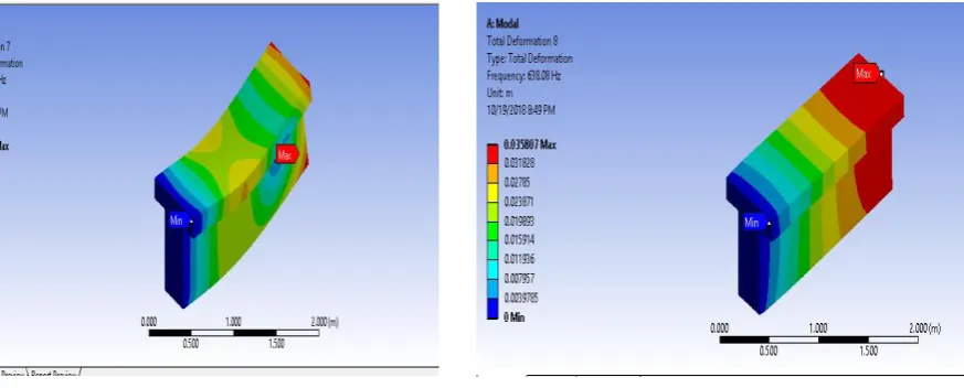
[image:6.595.73.549.100.274.2]6.4.Mode Shapes of Aluminum
[image:6.595.73.545.316.487.2]Fig.17: First Frequency and Mode Shape Fig. 18: Second Frequency and Mode Shape
Fig. 19: Third Frequency and Mode Shape Fig. 20: Fourth Frequency and Mode Shape
[image:6.595.100.537.520.696.2]Available online at www.ijrat.org
6.5.Comparison of Frequencies of the Results Obtained:The values of frequencies obtained during simulation study with chosen materials
are tabulated in the table no: 2 as shown below.
Table 2: Table of comparison of frequencies
Material
Frequency Structural Steel (Hz) Mild Steel (Hz) Aluminium (Hz) Mode
1 88.417 59.198 88.82
2 151.12 74.954 151.56
3 231.12 347.94 229.72
4 442.96 398.94 443.43
5 598.31 446.31 597.21
6 635.2 924.39 638.08
7. CONCLUSIONS
The vibration analysis of a structure holds a lot of significance in its designing and performance over a period of time. The verification of the analytical approach with a considerable amount of experimental data has to be carried out that, the analytical approach enables one to obtain well-founded relationships between different dynamic characteristics to solve the problem.
The study in this work is necessary for a correct and thorough understanding of the Vibration analysis techniques.
The results obtained in this study can be concluded as follows.
The natural frequency of beam increases with number of mode shapes.
The frequency for Structural steel increases from 88.417 to 635.2 Hz with increase in mode shapes
The frequency of Mild steel increases from 59.198 to 924.39 Hz with increase in mode shapes
For Aluminum, the frequency increases from 88.82 to 638.08 Hz
It may be concluded that the material Structural Steel can sustain vibrations when compared to Mild steel and Aluminum.
It is observed that, the material Mild steel may not be sustaining vibrations when compared to the other materials, Structural Steels and Aluminum
REFERENCES
[1] Miss.PatilVarsha B. , S.V.Lale , Y.P.Pawar , Dr. C. P. Pise , “Vibration Analysis of I Section Cantilever Beam”, Volume 6, Issue 6, June 2017, ISSN: 2278-7798
[2] Malay Quila, Prof. Samar Ch. Mondal, Prof. SusenjitSarkar, “Free Vibration Analysis of an Uncracked & Cracked Fixed Beam” IOSR Journal of Mechanical and Civil Engineering (IOSR-JMCE) e-ISSN: 2278-1684, p-ISSN: 2320-334X, Volume 11, Issue 3 Ver. III (May- Jun. 2014), PP 76-83.
[3] M.P.Kolhe, Prof .V.D.Wakchaure , Prof .A.V.Deokar, “Vibration analysis of cantilever beam with multiple cracks using natural frequency as basic criterion” , Vol-1 Issue-3 2015, ISSN(O)-2395-4396.
[4] Mr. P.Kumar, Dr. S.Bhaduri, Dr. A. Kumar, “Vibration Analysis of Cantilever Beam: An Experimental Study”, Volume 4 Issue II, February 2016 ISSN: 2321-9653 [5] SreekanthSura, AlkaSawale, M Satyanarayana
Gupta ,”DYNAMIC ANALYSIS OF CANTILEVER BEAM”, Volume 8, Issue 5, May 2017, pp. 1167–1173
[6] Lanka Ramesh, P.SrinivasaRao ,K.Ch.Kishoe Experimental and Finite Element Model Analysis of un-cracked and cracked Cantilever beam International Journal of Advanced Research in Science, Engineering and Technology Vol. 3, Issue 1 , PP 1266-1274. [7] Nirmall.T, Dr.Vimala.S, Free Vibration