R E S E A R C H
Open Access
Versatile mobile communications
simulation: the Vienna 5G Link Level Simulator
Stefan Pratschner
1,2*, Bashar Tahir
1,2, Ljiljana Marijanovic
1,2, Mariam Mussbah
2, Kiril Kirev
2,
Ronald Nissel
1,2, Stefan Schwarz
1,2and Markus Rupp
2Abstract
Research and development of mobile communications systems require a detailed analysis and evaluation of novel technologies to further enhance spectral efficiency, connectivity and reliability. Due to the exponentially increasing demand of mobile broadband data rates and challenging requirements for latency and reliability, mobile
communications specifications become increasingly complex. For this reason, analytic analysis as well as measurement-based investigations of link-level methods soon encounter feasibility limitations. Therefore,
computer-aided numeric simulation is an important tool for investigation of wireless communications standards and is indispensable for analysis and development of future technologies. In this contribution, we introduce the Vienna 5G Link Level Simulator, a MATLAB-based link-level simulation tool that facilitates research and development in mobile communications. Our simulator enables standard compliant setups according to 4G LTE, 5G NR and even beyond, making it a very flexible simulation tool. Offered under an academic use license free of charge to fellow researchers, it considerably enhances reproducibility in wireless communications research.
Keywords: Mobile communications, 5G, New radio, Link-level simulation
1 Introduction
Link-level measurements, analysis and simulation are fundamental tools in the development of novel wireless communication systems, each offering its own unique benefits. Measurements provide the basis for channel modeling and present the ultimate performance bench-mark of any transceiver architecture and are thus a pre-requisite of analysis and simulations. However, perform-ing measurements is very costly, time consumperform-ing and hard to adapt to specific communication scenarios. A big advantage of analytic investigations is their potential to reveal relationships amongst key parameters of a sys-tem. Yet, analytic tractability often requires application of restrictive assumptions and simplifications, limiting the value of analytic results under realistic conditions. To investigate highly complex systems, such as wireless transceivers, and to efficiently evaluate the performance of novel technologies, link-level simulations are thus often
*Correspondence:[email protected]
1Christian Doppler Laboratory for Dependable Wireless Connectivity for the Society in Motion, Vienna, Austria
2Institute of Telecommunications, TU Wien, Gußhausstraße 25/389, 1040 Vienna, Austria
the preferred method of choice. It enables the incorpora-tion of realistic and practical constraints, which in many cases significantly alter the picture drawn by purely ana-lytic investigations. Nevertheless, only by complementing measurements, analysis and simulations, it is possible to reap the benefits of all three approaches.
In this paper, we introduce the newest member of our suite of Vienna Cellular Communications Simula-tors (VCCS), the Vienna 5G link level (LL) Simulator, to the community. Our mobile communications research group at the Institute of Telecommunications at TU Wien has a long and successful history of develop-ing and shardevelop-ing standard-compliant cellular communi-cations simulators under an academic use license. We thereby enhance reproducibility in wireless communica-tions academic research [1, 2]. The implementation of the Vienna LTE Simulators [3] started back in 2009, lead-ing to three reliable standard compliant LTE simulators: a downlink system level simulator [4, 5] and two link level simulators, one for uplink [6] and one for down-link [7]. Although the path of 3rd Generation Partnership Project (3GPP) towards 5G is largely based on Long Term Evolution (LTE), evolving our LTE simulators towards
5G is not straightforward due to a lack of flexibility of the simulation platform in terms of implementation and functionality. Mobile communications within 5G is expected to support much more heterogeneous and ver-satile use cases compared to 4G, such as enhanced mobile broadband (eMBB), massive machinetype communication (mMTC) or ultra-reliable and low-latency communica-tion (uRLLC). Furthermore, a multitude of novel con-cepts introduced within 5G, e.g., full-dimension/massive multiple-input multiple-output (MIMO) beamforming [8–10], mixed numerology multicarrier transmission [11, 12], non-orthogonal multiple access [13, 14], and transmission in the millimeter wave (mmWave) band [15, 16], are demanding detailed analysis. We therefore decided to extend our VCCS simulator suite and to evolve to the next generation of mobile communications with dedicated 5G link and system level simulators.
The Vienna 5G LL Simulator focuses on the physi-cal layer (PHY) of the communication system. Corre-spondingly, the scope is on point-to-point simulations of the transmitter-receiver chain (channel coding, MIMO processing, multicarrier modulation, channel estimation, equalization) supporting a broad range of simulation parameters. Within our LL simulator, no abstract mod-els for the transmission of bits over the wireless channel are employed. Instead, the whole transmitter and receiver chain and the signal transmission over a wireless chan-nel is implemented up to the individual signal samples and thus provides a very high level of detail and accu-racy. Nevertheless, multi-point communications with a small number of transmitters and receivers (limited only by computational complexity) are possible to simulate, e.g., multi-point precoding techniques [17], rate splitting approaches [18] or interference alignment concepts [19].
The simulator allows for (and includes) parameter set-tings that lead to standard compliant systems, including LTE as well as 5G. It is further offers the possibility to parametrize any orthogonal frequency division multi-plexing (OFDM)-based wireless system such as WiMAX, IEEE 802.11a/p or similar, and simulate their co-existence. Yet, the versatile functionality of the simulator pro-vides the opportunity to go far beyond standard compli-ant simulations, enabling, e.g., the evaluation of various combinations of PHY settings as well as the co-existence investigation of candidate 5G technologies. The simula-tor is implemented in MATL AButilizing object oriented programming methods and its source code is available for download under an academic use license [2]; hence, we attempt to continue our approach of facilitating repro-ducible research with this unifying simulation platform. The Vienna 5G LL Simulator acts in close orchestra-tion with its sibling the Vienna 5G system level (SL) Simulator: the LL simulator is employed to determine the PHY abstraction models utilized on SL to facilitate
computationally efficient simulation of large-scale mobile networks.
The goal of this contribution is to introduce the Vienna 5G LL Simulator to the research community and offer this versatile and flexible simulation tool under an academic use license free of charge to enhance reproducibility in research. To clarify our scientific contribution, we com-pare our new simulator to other available simulation tools in Section 2. Further, we point out specific use cases and scenarios relevant for future mobile communications systems, also in Section 2. The general structure of the simulator is described in Section3and the implemented features are explained in more detail in Section4. Simu-lations for the previously mentioned exemplary use cases are discussed and shown in Section5.
2 Scientific contribution
Computer-aided numerical simulations are a well-established tool for analysis and evaluation of wireless communications systems. Hence, a number of commer-cial and academic link-level simulators is offered online. Amongst these tools, our new Vienna 5G LL Simula-tor supports a variety of unique features as well as a highly flexible implementation structure that allows for easy integration of additional components. In this section, we provide an overview of existing similar simulation platforms and compare them to our new simulator. We thereby restrict to academic tools that are, as our lator, available for free, and leave aside commercial simu-lators. Further, we point out the distinct features offered by the Vienna 5G LL Simulator and thereby state our scientific contribution.
2.1 Related work - existing simulation tools
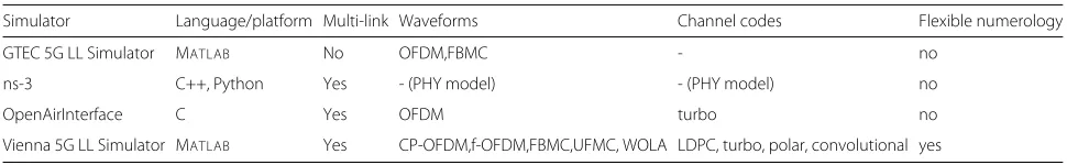
With each new wireless communications standard, the need for simulation emerges. This is necessary for the evaluation, comparison and further research as well as the development of communication schemes, specified within a certain standard. The existence of various sim-ulation tools for the PHY of LTE, such as [20,21] or the Vienna LTE-A LL Simulator [3, 6, 7], developed by our research group, supports this claim. These tools, how-ever, are mainly based on 3GPP Release 8 to Release 10 and do not offer features and functionality specified and expected for 5G. There exist some commercial products, that is, link-level simulators, that claim to support sim-ulation of 5G scenarios. However, as we aim to support academic research also beyond the currently standardized features, we compare our Vienna 5G LL Simulator to other freely available academic simulators only. An overview of existing LL simulation tools is provided in Table1.
Table 1Overview of existing LL simulators
Simulator Language/platform Multi-link Waveforms Channel codes Flexible numerology
GTEC 5G LL Simulator MATLAB No OFDM,FBMC - no
ns-3 C++, Python Yes - (PHY model) - (PHY model) no
OpenAirInterface C Yes OFDM turbo no
Vienna 5G LL Simulator MATLAB Yes CP-OFDM,f-OFDM,FBMC,UFMC, WOLA LDPC, turbo, polar, convolutional yes
implementation based on modules. By implementation of new modules, it is even possible to simulate different wireless communications standards, such as WiMAX or 5G. The current 5G module offers two PHY transmis-sion waveforms, namely OFDM and filter-bank multicar-rier (FBMC). Forward error correction channel coding is not supported. Further, this simulator focuses on single-link performance and does support neither multi-user nor multi-transmitter (multi base station (BS)) scenarios. Simulating interuser interference (IUI) of non-orthogonal users, e.g., non-orthogonal multiple access (NOMA) or mixed numerology use cases, is not possible with this tool. A well-known tool for simulation of communications networks is thens-3 simulator [23], which is the succes-sor of the ns-2 simulator. Although this tool has to be understood as a set of open source modules forming a generic network simulator, there exists an LTE module [24] that allows to simulate 4G networks. Further, there exists a module [25,26] that covers mmWave propagation aspects of 5G. Still, the main focus of thens-3 simulator lies on network simulations. The mentioned LTE mod-ule models radio resources with a granularity of resource blocks and does not consider time signals on a sample basis, as our simulator does. Therefore, thens-3 simulator does not provide the detailed level of PHY accuracy that distinguishes pure link-level simulation tools from sys-tem and network-level simulators, where a certain degree of physical layer abstraction is unavoidable to manage computational complexity.
The OpenAirInterface is an open source platform offered by the Mobile Communications Department of EURECOM [27]. Currently, the implementation is based on 3GPP Rel. 8 and supports only parts of later releases. The platform offers flexibility that allows for simulation of aspects of future mobile communications standards, such as cloud radio access network (RAN) or software defined networking. The simulation platform supports the simula-tion of the core network as well as the RAN and considers the complete protocol stack from the PHY to the net-work layer. It offers two modes for PHY emulation, where the more detailed mode even considers actual transmis-sion of signals over emulated channels. Still, this simulator focuses on simulation of networks in terms of a com-plete protocol stack implementation. However, details of PHY transmissions, such as waveform, channel coding,
numerology or reference signals for channel estimation and synchronization, are not considered.
Accurate LL simulations require sophisticated chan-nel models that realistically represent practically relevant propagation environments. Since 5G introduces novel PHY technologies, such as, full-dimension MIMO and transmission in the mmWave band, also channel models need to be updated and revised. The modular implemen-tation structure of our simulator supports easy integration of dedicated wireless channel models and emulators, such as [28] or [29,30].
2.2 Scientific contribution and novelty of our simulator
The currently ongoing evolution from LTE towards 5G shows that LL simulations are still a very active research topic, since many different candidate RAN and PHY schemes need to be gauged and compared against each other. The Vienna 5G LL Simulator supports these needs and allows for a future-proof evaluation of PHY tech-nologies due to its versatility. The simulator allows almost all PHY parameters to be chosen freely, such that any multicarrier system can be simulated; specifically, by set-ting parameters according to standard specifications, it is possible to conduct standard-compliant simulation of LTE or 5G (we provide corresponding parameter files in the simulator package). Due to the modular structure and application of object-oriented programming, further functionality, such as additional channel models, can eas-ily be included.
Our LL simulator focuses on simulating PHY effects in a high level of detail. It considers the actual transmis-sion of time signals over emulated wireless channels in a granularity of individual samples. This allows the detailed analysis of PHY schemes of current and future mobile communications systems, e.g., investigating the impact of the channel delay and Doppler spread on various PHY waveforms and numerologies (see Section5.1).
The following specific aspects distinguish our Vienna 5G LL Simulator from the tools summarized in Section2.1.
• PHY methods even beyond 5G: As mentioned above, the simulator supports standard-compliant
simulation of the physical downlink shared channel/physical uplink shared channel of LTE and 5G by implementing the signal processing chains described in [31,32]. Yet, simulation parameters of adaptive modulation and coding (AMC), MIMO processing and baseband multicarrier waveforms are not restricted to standard-compliant values. In addition, the modular simulator structure allows for easy integration of novel functionality, such as additional waveforms or modulation and coding schemes (MCSs), to investigate candidate technologies of future mobile communication systems. As an example, we have implemented FBMC transmission to support comparison with the filtered/windowed OFDM-based waveforms considered within 5G standardizations (weighted overlap and add (WOLA), universal filtered multicarrier (UFMC), filtered OFDM (f-OFDM)). • Flexible numerology: As introduced by 3GPP for 5G,
the concept of flexible numerology describes the possibility to adapt the time and frequency span of a resource element. This means that the subcarrier spacing and the symbol duration of the multicarrier waveform are adaptable to support a variety of service requirements (latency, coverage, throughout), channel conditions (delay or Doppler spread) and carrier frequencies. As these parameters are freely adjustable in our simulator, effects of different numerologies are investigatable, even beyond the standardized range [32]. To summarize, the simulator enables comparison and optimization of numerologies of several multicarrier waveforms (see Section4.2) in combination with various channel codes (see Section4.1) under arbitrary channel conditions in terms of delay and Doppler spread. • Multi-link simulations: The Vienna 5G LL Simulator
is capable of simulating multiple users and BSs (only restricted by computational complexity). Although analysis of large networks with a high number of users and BSs is not the goal of a link-level simulation, this
feature allows investigation of IUI. While this feature was not required for LTE’s LL, since user signals within a cell were automatically orthogonal due to the application of OFDM with a fixed numerology, it is interesting in the context of 5G as users with different numerologies are not orthogonal anymore. The Vienna 5G LL Simulator enables the investigation of IUI in such mixed numerology use-cases.
3 Simulator structure
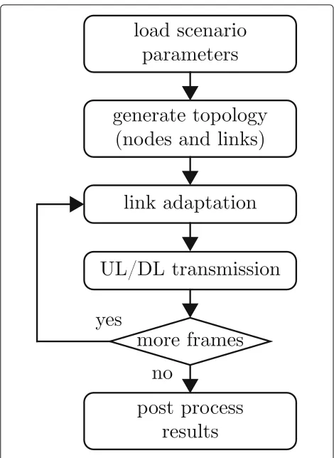
In this section, we provide a short general description of the Vienna 5G LL Simulator and a brief introduction of the simulator’s structure. The general structure of our simu-lator is similar to any other link-level simusimu-lator, see for example Figs. 1, 2, 3 in [1] or Figs. 2, 3, 4 in [22]. Still, as our implementation is entirely new, modular and there-fore flexible, we provide a brief description of our specific implementation. In addition to this overview, supplemen-tary documents, such as a user manual as well as a detailed list of features, are provided on our dedicated simulator web page [2].
Link-level simulations in most cases assume a fixed signal-to-noise ratio (SNR) for the transmission link between transmitter and receiver. We slightly deviate from this common approach in our simulator, since we support multiple different waveforms that achieve different SNRs for a given total transmit power. Hence, rather than fix-ing the SNR, we fix the transmit and noise power and determine the SNR as a function of the applied waveform. Additionally, since we support multi-link transmissions, we introduce individual path loss parameters for these links, to enable controlling the SIR of the individual con-nections. However, in contrast to an SL simulator, we do not introduce a spatial network geometry to determine the path loss, but rather set the path loss as an input parameter of the simulator. The goal of LL simulations is to obtain results in terms of PHY performance metrics, such as throughput, bit error ratio (BER) or frame error ratio (FER), which are representative for the average sys-tem performance within the specified scenario. To this end, Monte Carlo simulations are carried out and results are averaged over a certain number of channel, noise and data realizations. To gauge the statistical significance of the obtained results, the simulator calculates the corre-sponding 95 percentile confidence intervals (default).
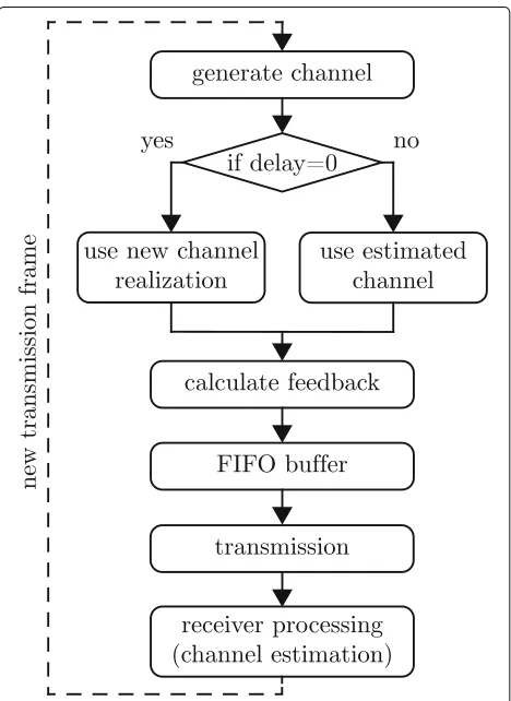
Fig. 1Basic simulation work flow
The connections can serve as downlink, uplink, or sidelink (device-to-device link). Furthermore, inter- and intra-cell interference is easily captured, as it only requires to estab-lish the corresponding connections between the suppos-edly interfering nodes.
Every connection is represented in the simulator by a so-called link object. It is the most fundamental building block of the simulator and contains all the PHY function-ality objects, such as channel coding, modulation, MIMO processing, channel generation and estimation and chan-nel state information (CSI) feedback calculation. More-over, the link object also contains the generated signals throughout the whole transceiver chain of the specific connection.
There exists no limitation for the number of BSs or users for a simulation. The size of the simulated wire-less network is only limited by simulation complexity. Considering the most demanding parts in terms of com-putational power within the link object to be the channel coding and decoding, the simulation complexity increases linearly with the number of links between two nodes.
After the network topology is specified, the next step in the scenario setup is to enter the transmission parameters. This covers the whole transmission chain, including the
specification of the applied channel coding scheme, the multicarrier waveform, the applied channel model, as well as the equalizers and decoders employed by the receiver. Parameters can either be set locally for each link and node, or conveniently globally, in case all links and nodes use the same settings. Setting different parameters for different links enables coexistence investigations of mul-tiple technologies; for example, one cell could be set up to operate with OFDM and turbo coding while the other cell uses FBMC with low-density parity-check (LDPC) coding. This allows to investigate the sensitivity w.r.t. out-of-cell interference of such systems. Notice, since signals are processed on a sample basis, the modeling of such interference is highly accurate.
Once the scenario file is ready, it gets loaded by the main script of the simulator, where the simulation is set up according to the input topology and parameters. The simulation is carried out on a frame-by-frame basis over a specified sweep parameter, such as the path loss, transmit power, or velocity. Please note that the velocity determines the maximum Doppler shift of the user’s channel only; as there is no geometry in an LL simulator, the user has no physical position that changes over time.
Within the simulation, the simulator performs full down- and uplink operation of all specified transmission links, including the possibility to activate LTE compli-ant CSI feedback as well as link adaptation in terms of AMC and standard-compliant MIMO processing (see Section 4.4). The results for all nodes in the form of throughput, FER, and BER versus the sweep parameter (e.g., SNR) are provided as simulator output. In addi-tion to these aggregated results, the simulator also stores simulation results of individual frames, to support fur-ther post-processing by the researcher. The overall pro-cedure is optimized in such a way that the overhead of the exchanged information during the simulation is mini-mal, and the operations are executed efficiently. Moreover, parallelism can be enabled over the loop of the sweep parameter, which offers a substantial reduction in simula-tion time when run on multi-processor machines.
4 Features
In this section, we provide a more detailed description of the Vienna 5G LL Simulator. The main components and features are described, giving insights in the available ver-satile functionality. To highlight features that make our LL simulator unique, we further provide and discuss results of exemplary simulations in Section5. All of these exam-ple scenarios are included with the simulator download package and are straightforward to reproduce.
4.1 Channel coding
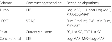
capability is provided to the transmitted signal. The sim-ulator supports the four coding schemes of convolu-tional, turbo, LDPC, and polar codes. These schemes were selected by 3GPP as the candidates for 5G, due to their excellent performance and low complexity state-of-the-art implementation. Table 2 summarizes the supported channel coding schemes and their corresponding decod-ing algorithms.
The turbo and convolutional codes are based on the LTE [33] standard, the LDPC code follows the 5G new radio (NR) [34] specifications, and for polar codes, we currently use the custom construction in [35] concatenated with an outer cyclic redundancy check (CRC) code. This includes both the construction of the codes and also the whole seg-mentation and rate matching process as defined in the standards.
The decoding of convolutional and turbo codes is based on the log-domain BCJR algorithm [36], that is, the Log-MAP algorithm, and its low complexity variants of MAX-Log-MAP [37] and Linear-Log-MAP [38]. For the LDPC code, the decoder employs the Sum-Product algorithm [39], and its approximations of the Min-Sum [40] as well as the double piecewise linear PWL-Min-Sum [41]. The LDPC decoder utilizes a layered architecture where the column message passing schedule in [42] is applied. This allows for faster convergence in terms of the decoding iterations. As for polar codes, the decoder is based on the log-domain successive cancellation (SC) [43], and its extensions of List-SC and CRC-aided List-SC [44].
4.2 Modulation
According to the current 3GPP specifications related to the NR PHY design, equipment manufacturers are uncon-strained in the choice of OFDM-based multicarrier wave-forms [45]. Cyclic prefix OFDM (CP-OFDM) will be the baseline multicarrier transmission scheme applied in 5G. However, to reduce out of band (OOB) emissions and improve spectral confinement, manufacturers are free to add windowing or filtering on top of CP-OFDM. Our sim-ulator offers the versatility to support various multicar-rier waveforms. Besides OFDM-based waveforms, such as CP-OFDM, WOLA, UFMC, and f-OFDM, we addi-tionally support FBMC as a promising candidate for the next generations beyond 5G [46]. In the following, we
Table 2Supported channel coding schemes
Scheme Construction/encoding Decoding algorithms
Turbo LTE Log-MAP, Linear-Log-MAP,
MAX-Log-MAP
LDPC 5G NR Sum-Product, PWL-Min-Sum,
Min-Sum
Polar Currently custom SC, List-SC, CRC-List-SC
Convolutional LTE Log-MAP, MAX-Log-MAP
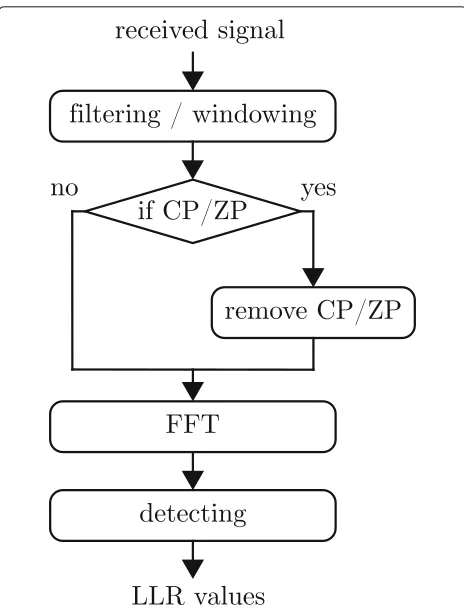
provide a brief description of each waveform supported by our simulator. The basic signal flowcharts applied for signal generation and reception at the transmitter and receiver, respectively, for all of these waveforms are shown in Figs.2and 3. In general, the filtering and windowing operations are applied in time domain, after the inverse fast Fourier transform (IFFT). Depending on the modula-tion scheme, these operamodula-tions are performed per subband (UFMC), per subcarrier (WOLA,FBMC) or on the whole band (FOFDM). Some of the schemes employ CP, such as CPOFDM, WOLA and f-OFDM, or zero prefix (ZP), such as UFMC, in order to prevent distortion caused by the multipath channel and by filtering or window-ing. To mitigate potential IUI (or inter-subband interfer-ence), windowing/filtering is also applied at the receiver side [47].
4.2.1 Cyclic prefix OFDM
Proposed in the downlink of the current LTE system, CP-OFDM is currently the most prominent multicarrier waveform, since it is the standardized waveform not only of LTE downlink, but also for WiFi 802.11 [48]. It assumes a rectangular pulse of duration T = TOFDM +TCP at the transmitter, whereTOFDMis the useful symbol dura-tion andTCPis the length of CP. This pulse shape enables very efficient implementation by means of an IFFT at the transmitter side and an FFT at the receiver side. Unfor-tunately, the rectangular pulse also causes high OOB
Fig. 3Processing of the received signal. This general principle is applicable for all supported multicarrier schemes
emissions. By applying a CP, the scheme avoids intersym-bol interference (ISI) and preserves orthogonality between subcarriers in the case of highly frequency selective chan-nels. This simplifies equalization in frequency-selective channels, enabling the use of simple one-tap equalizers, but reduces the spectral efficiency at the same time due to the overhead.
4.2.2 Weighted overlap and add
WOLA extends OFDM by applying signal windowing in the time domain [49]. Unlike conventional OFDM, which employs a rectangular prototype pulse, WOLA applies a window that smooths the edges of the rectangular pulse, improving spectrum utilization. The window shape is based on the (root) raised cosine function determined by a roll-off factor that controls the windowing function. Due to this windowing function, consecutive WOLA sym-bols overlap in time. This effect is compensated for by extending the length of the CP. In that way, the scheme preserves the orthogonality of symbols and subcarriers, but it increases the overhead of the CP and therefore reduces the spectral efficiency compared to OFDM. At the receiver side, windowing in combination with an overlap and add operation further reduces IUI [46].
4.2.3 Universal filtered multicarrier
As an alternative to windowing, filtering can be applied to OFDM waveforms to reduce out-of-band emissions. UFMC employs subband-wise filtering of OFDM and is therefore an applicable waveform for 5G NR [50]. Compared to OFDM, UFMC provides better suppres-sion of side lobes and supports more efficient utilization of fragmented spectrum. In our simulator, we follow the transceiver structure proposed in [50,51]. At the trans-mitter side, we apply a subband-wise IFFT, generating the transmit signal in time domain. In order to reduce OOB emissions, we apply filtering on a set of contiguous sub-carriers, so-called subbands. There are several criteria for the filter design. In our simulator, we employ the Dolph-Chebyshev filter since it maximizes the side lobe attenua-tion [52]; however, other filters can easily be implemented. UFMC employs a ZP in order to avoid ISI on time disper-sive channels, although there are only minor differences compared to the utilization of a CP [53]. To restore the cyclic convolution property similar to CP-OFDM, which enables low-complexity FFT-based equalization, the tail of the received signal is added to its beginning at the receiver side.
4.2.4 Filtered OFDM
Very similar to UFMC is f-OFDM; however, unlike UFMC, which applies filtering on a chunk of consecutive subcarri-ers, FOFDM includes a much larger number of subcarriers which are generally associated to different use cases [54]. FOFDM employs filtering at both, transmitter and receiver side. If the total CP length is longer than the combined filter lengths, the scheme restores orthogonal-ity in an additive white Gaussian noise (AWGN) channel. Hence, compared to CP-OFDM, the CP length is gener-ally longer and thus the overhead is increased. However, in order to keep the overhead at a minimum, the method usually allows a small amount of self-interference. The introduced interference is controlled by the filter length and the CP length. Currently, our simulator supports a fil-ter based on a sinc pulse which is multiplied by a Hanning window, yet any other filter can easily be incorporated.
4.2.5 Filter-bank multicarrier
the case of doubly-selective channels, the method is able to significantly suppress ISI and intercarrier interference (ICI) using conventional equalizers, such as a minimum mean squared error (MMSE) equalizer [55,56]. However, for channel estimation or in the case of MIMO trans-missions, imaginary interference has a more significant impact and requires a special treatment [57].
4.3 MIMO transmissions
The Vienna 5G LL Simulator supports arbitrary antenna configurations and various MIMO transmission modes. Not only may the number of transmit and receive anten-nas be set to any value, also this parameter is individually adjustable for each node. The behaviour of the MIMO transmitter and receiver is selected via the transmission mode. Currently, the available options are transmit diver-sity, open loop spatial multiplexing (OLSM), closed loop spatial multiplexing (CLSM) and a custom transmission mode that is freely configurable. The transmit diversity mode leads to a standardized version of Alamouti’s space-time codes [31]. OLSM and CLSM both are LTE stan-dard compliant MIMO transmission modes, where link adaptation is performed according to Section 4.4. The additional custom transmission mode allows a flexible set-ting of parameters. For this configuration, the number of active spatial streams, the precoding matrix as well as the MIMO receiver are freely selectable. Currently zero forc-ing, MMSE, sphere decoding and maximum likelihood (ML) MIMO detectors are implemented.
4.4 Feedback
To adapt the transmission parameters to the current chan-nel conditions, CSI at the transmitter is required. Since up- and downlink are implemented for frequency-division duplexing mode, the reciprocity of the channel cannot be exploited. For non-reciprocal channels, the receiver has to estimate the channel and then feed back the CSI to the transmitter. To reduce the overhead, the fed back CSI is quantized. The feedback calculation is an intelligent way of quantizing the CSI, it comprises the precoding matrix indicator (PMI), rank indicator (RI) and channel qual-ity indicator (CQI). By the CQI feedback, the transmitter selects one of 15 MCSs. By the PMI, the transmitter selects a precoding matrix from a codebook and the RI informs the transmitter about the number of active transmission layers.
The algorithm for calculation of the feedback parame-ters is based on [58, 59]. To reduce the complexity, the feedback calculation is decomposed into two separate steps. In the first step, the optimum PMI and RI are jointly evaluated, maximizing the sum mutual information over all scheduled subcarriers. In the second step, we choose the CQI with the largest rate that achieves a block error ratio (BLER) below a certain threshold. The CQI value is
found by mapping the post equalization signal to interfer-ence and noise ratio (SINR) of all scheduled subcarriers to an equivalent AWGN channel SNR.
Figure4shows a flowchart describing the feedback pro-cess. The feedback channel is modeled as simple delay, which is implemented by means of a FIFO buffer of cor-responding size; hence, we do not consider transmission errors in the feedback path, only the processing delay. For a feedback delay ofn > 0, the estimated channel is used at the receiver for the feedback calculation. The calcu-lated feedback is then fed into the FIFO buffer. For the first n transmissions, all three feedback parameters are set to the default value 1. The delay has to be sufficiently smaller than the coherence time to ensure similar chan-nel conditions. The feedback calculation is placed after the generation of the channel and before the transmission. This enables simulations with instantaneous (zero delay) feedback as the newly generated channel is immediately available for the feedback calculation.
For the CLSM and OLSM transmission modes, the feed-back is configured automatically, whereas for the custom transmission mode the feedback is configured manually in the scenario file. For all three transmission modes, the
feedback delay and the type of averaging within the SINR mapping have to be set in the scenario file.
4.5 Channel models
As the aim of LL simulation is acquisition of the average link performance, many random channel realizations are necessary per scenario. There exists no network geome-try and therefore no path-loss model. A link’s path-loss is an input parameter, determining the user’s average SINR. Therefore, the channel model only includes small-scale fading effects while its average power is dictated by the given path-loss.
The use of a universal spatial channel model, such as the QUADRIGA model [28] or the 3GPP 3D channel model [60, 61], is of limited benefit due to the lack of geome-try. We offer frequency selective and time selective fading channel models. The frequency selectivity is implemented as tapped delay line (TDL) model. Currently, we offer implementations for Pedestrian A, Pedestrian B, Vehicu-lar A [62], TDL-A to TDL-C [63], Extended Pedestrian A and Extended Vehicular A [64]. To model the chan-nel’s time selectivity, the fading taps change over time to fit a certain Doppler spectrum. A Jakes’s as well as a uniform Doppler spectrum are currently implemented. Jakes’s model also supports time-correlated fading across frames according to a model from [65] with a modification from the appendix of [66]. For time-invariant channels, the two-wave with diffuse power (TWDP) fading model [67] is employed, which is a generalization of the Rayleigh and Rician fading models. In contrast to the Rayleigh fad-ing model, where only diffuse components are considered, and the Rician fading model, where a single specular com-ponent is added, two specular comcom-ponents together with multiple diffuse components are considered in the TWDP fading model. The two key parameters for this model are Kand. Similar to the Rician fading model, the param-eterK represents the power ratio between the specular and diffuse components. The parameter is related to the ratio between peak and average specular power and thus describes the power relationship between the two specular components. By proper choice ofK and, the TWDP fading model is able to characterize small-scale fading for a wide range of propagation conditions, from no fading to hyper-Rayleigh fading. Table3shows typical
Table 3Parameters of the TWDP fading model
Fading statistic K
No fading ∞ 0
Rician >0 0
Rayleigh 0
-Hyper-Rayleigh ∞ ≈1
For the case of a time-invariant channel, the TWDP fading is parametrized byKand
parameter combinations and their corresponding fading statistic. In contrast to classical models, the TWDP fad-ing model allows for destructive interference between two dominant specular components. This enables for a possi-ble worse than Rayleigh fading behaviour, depending on the fading model parameters.
Spatial correlation of MIMO channels is implemented via a Kronecker correlation model with correlation matri-ces as described in [68].
4.6 Non-orthogonal multiple access
Massive connectivity and low latency operation are one of the main drivers for future communications systems. One promising solution addressing these requirements is NOMA [14]. It allows multiple users to share the same orthogonal resources in a non-orthogonal manner. This increases the number of concurrent users and allows them to transmit more often. Currently, the simulator supports a downlink version based on the 3GPP multi-user superposition transmission (MUST) item [69], with more schemes planned for future releases of the simula-tor. MUST allows the BS to transmit to two users using the same frequency, time, and space by superimposing them in the power-domain. One of those users has good channel conditions (strong user), while the other one has bad channel conditions (weak user), such as a cell-edge user. The standard defines three power-ratios that con-trol how much power is allocated to each user. In either case, the weak user gets most of the power in order to help it overcome its harsh conditions. At the receiver side, the interference from the high power user is miti-gated by means of successive interference cancellation, or by directly applying ML detection on the superimposed composite constellation.
5 Use cases for 5G
Future mobile communications systems offer an increased degree of flexibility and wide range of parametrization to meet a heterogeneity of service requirements. For inves-tigation of this large variety of new features, we offer a simulation tool, able to cover many currently discussed aspects for 5G and beyond. To introduce capabilities of our simulator and offer increased insights in its function-ality, we demonstrate simulation of selected use cases for future mobile communications systems in this section. To our best knowledge, there is no other link-level simulator freely available in academia that is capable of performing the following simulations in the presented form.
5.1 Flexible numerology
and eMBB, as well as to adapt to varying user’ channel conditions, 3GPP introduces a flexible numerology for the 5G PHY. The numerology of a multicarrier scheme refers to the time and frequency parametrization of the PHY waveform, i.e., the subcarrier spacing, symbol duration and CP length. In this section, an example simulation sce-nario, demonstrating the concept and potential of flexible numerology, is presented.
The proper choice of numerology depends on the ser-vice requirements of a user as well as its channel condi-tions, and it usually results from their interplay. Current 4G LTE wireless technology provides only a fixed subcar-rier spacing of 15 kHz, regardless of the carsubcar-rier frequency and channel conditions. This is not appropriate for future 5G systems that will operate over a large spectrum range. One reason is that the channel-induced Doppler spread of the received signal, which causes ICI, as described in [70], scales proportionally with the carrier frequency and the user velocity. Hence, to accommodate higher carrier fre-quencies and high user mobility without incurring exces-sive ICI, the subcarrier spacing must be scaled with the carrier frequency and the user velocity. This is especially important in the mmWave band, where even pedestrian speed leads to Doppler shifts of several hundred Hertz. Similarly, it is necessary to adapt the numerology accord-ing to the frequency selectivity of the channel. Channels with large root mean squared (rms) delay spread require large CP duration to compensate for ISI, as considered in [71]. There, authors describe the impact of variable CP duration on the capacity performance and find the opti-mal CP duration over different channel models. Further-more, the subcarrier spacing for large rms delay spread should be small, to reduce the frequency-domain interpo-lation error of channel estimation. We show the impact of channel estimation error over different subcarrier spac-ings in [72], considering doubly selective channels. The optimal choice of numerology, however, is not only deter-mined by this interplay with channel conditions; it also needs to account for the requirements of the consid-ered service. For example, to achieve ultra low-latency for uRLLC services, clearly the transmission time interval length must be reduced, requiring shortening of the sym-bol duration and, hence, increasing the subcarrier spacing. This implies that perfectly matching the waveform param-eters to the channel conditions will not always be possible in practice.
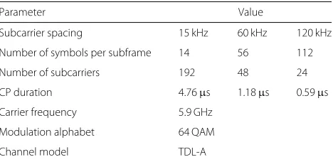
In our simulation, we focus on the interplay between the choice of numerology and channel conditions. Specif-ically, we investigate the sensitivity of different numerolo-gies w.r.t. the delay and Doppler spread of the channel. The parameters used for the simulations in this section are given in Table 4. We consider CP-OFDM as the PHY waveform and follow the 3GPP numerology structure [32]. This simulation setup corresponds to the scenario
Table 4Parameters for the flexible numerology simulation example
Parameter Value
Subcarrier spacing 15 kHz 60 kHz 120 kHz
Number of symbols per subframe 14 56 112
Number of subcarriers 192 48 24
CP duration 4.76μs 1.18μs 0.59μs
Carrier frequency 5.9 GHz
Modulation alphabet 64 QAM
Channel model TDL-A
Three different numerologies are employed
flexibleNumerology, which is included with the simulator download package to enhance reproducibility. According to 3GPP, subcarrier spacings for 5G are scaled versions of the basic 15 kHz subcarrier spacing by a factor 2k, where kis an integer in the range from 0 to 5. In our simulation example, we consider three values for subcarrier spac-ings, namely 15 kHz, 60 kHz and 120 kHz, corresponding to k = 0, k = 2 and k = 3, respectively. We keep the same bandwidth using different subcarrier spacings and vary the number of subcarriers and symbols propor-tionally. In order to represent channels with significantly different rms delay spread, we employ the TDL-A chan-nel model with rms delay spreads of τ = 45 ns and
τ = 250 ns [63]. The channel’s time selectivity is deter-mined according to Jakes’s Doppler spectrum, where the maximum Doppler frequencyfdis governed by the user’s velocityv, the carrier frequencyfcand the speed of light
c0, according to:fd = vfc0c. The range of Doppler shifts
in our simulations lies betweenfd = 82 Hz,
correspond-ing tov = 15 km/h, andfd = 1.64 kHz, corresponding
to v = 300 km/h at the considered carrier frequency of 5.9 GHz. We assume that the CP length scales with the subcarrier spacing to keep the CP overhead constant. In general, it would also be possible to keep the CP length constant for all subcarrier spacings; however, this implies an increased CP overhead with increasing subcarrier spacings, since the symbol duration becomes shorter. Therefore, 3GPP considers scaling of the CP length with the subcarrier spacing.
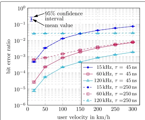
Fig. 5Simulation results of the flexible numerology example. The uncoded BER is considered for a sweep over user velocity for three different numerologies and two different channel rms delay spreads
largest subcarrier spacing of 120 kHz performs best in this case, since it experiences the least ICI. In general, we observe that the BER increases with user velocity due to growing ICI. This observation confirms previous theo-retical calculations performed in [74], where the authors analyze the influence of doubly selective channel on the BER performance in OFDM.
Considering the impact of the rms delay spread, we expect that smaller subcarrier spacings perform better, since they experience less ISI. Indeed, as we can observe in Fig.5when comparing solid-lines to dashed-lines at low velocity, where ISI dominates over ICI, our simulations confirm the expected behaviour. We observe significant performance degradation for 60 kHz and 120 kHz, since the CP length is not sufficient to cover the entire chan-nel PDP forτ = 250 ns. The 15 kHz subcarrier spacing behaves exactly the same atτ = 45 ns andτ = 250 ns, because the CP length for this subcarrier spacing is suf-ficient. Notice, though, that we assume perfect channel knowledge at the receiver. With real channel estimation, even the performance of the 15 kHz subcarrier spacing would degrade with increasing rms delay spread, due to increasing channel estimation error. This effect is analyti-cally derived in [75] and proved by simulations in [72].
5.2 Non-orthogonal waveforms
To support different user requirements and to offer the possibility to adapt transmission parameters to a user’s channel condition, 5G NR allows to employ a flexible numerology. Therefore, data from and to each mobile user may be transmitted with individual subcarrier spacings and symbol durations. Unlike LTE, user’s signals are not orthogonal anymore in 5G NR due to this concept of
mixed numerology or the employment of non-orthogonal waveforms, e.g., filtered versions of OFDM. When two non-orthogonal users are scheduled next to each other in the frequency domain, the OOB emissions of one user cause interference for the other user, and vice versa. Therefore, the IUI is dependent on the applied waveform and its OOB emission. The effect of interference becomes especially pronounced in cases where the received power of the users are significantly different, that is, if there exists a strong and a weak user. This situation occurs for exam-ple, if one user is close to the BS and another user is at the cell edge in an uplink transmission.
There exists analytic work on the IUI for the case of interfering OFDM or UFMC systems with different subcarrier spacing, consider [76] and references therein. However, analysis for other multicarrier systems, such as FBMC is still lacking. Even if expressions for the IUI power are available, it is not straight forward to predict the influence on the BLER or throughput of a standardized communications system such as LTE or 5G NR. There-fore, numerical simulation of the described IUI scenario is an approach to gain valuable insights in the interference behaviour of multicarrier systems.
In the sequel, we investigate an uplink transmission of two users with mixed numerology. User 1 employs a sub-carrier spacing of 15 kHz, which is still considered as the default subcarrier spacing in 5G NR, while User 2 employs 30 kHz, which is the next higher supported sub-carrier spacing within 5G NR [32]. Therefore, the two users transmit with non-orthogonal wave forms. In order to focus our attention on the effect of IUI only, we choose a fixed CQI value and choose a time invariant channel model with a very low rms delay spread.The users are scheduled next to each other in frequency as shown in Fig.6. The frequency guard band between the two users is a design parameter intended to reduce the IUI at the cost of spectral efficiency. In our simulation, we chose
a guard band of 60 kHz without any further optimiza-tion. We consider User 1 as the primary user that suffers from interference generated by User 2. In order to emu-late the situation of different received powers of different users, we vary the transmit power of interfering User 2. We expect that the IUI has a significant impact on User 1’s performance already at a point of equal transmit powers of User 1 and User 2. With increasing transmit power of User 2, the IUI will increase and User 1’s performance is expected to drop. As this effect is mainly determined by the OOB emissions of User 2, the severeness of impact on User 1’s performance will depend on the employed waveform.
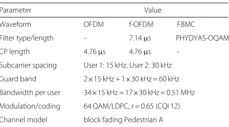
We simulate User 1’s throughput for different wave-forms, namely OFDM, f-OFDM and FBMC with simula-tion parameters summarized in Table5. The BS’s receiver is not interference aware. To enable reproducibility, this simulation corresponds to themultiLinkscenario, which is included in the simulator download package.
User 1’s transmit power is 30 dBm and its path loss is chosen such that it has a high SNR of approximately 40 dB. In this way, its throughput saturates at the maximum spectral efficiency of the employed CQI in the interfer-ence free case, that is, at low transmit powers of User 2. Results for a sweep over the interfering User 2’s trans-mit power are shown in Fig. 7. We observe that OFDM leads to the highest impact of interference as it has the highest OOB emissions of the three compared waveforms. When OFDM is employed, the throughput of User 1 is already decreasing significantly for a transmit power of 30 dBm of the interfering User 2. For f-OFDM, the impact of interference is also severe, however, due to the filtering and the reduced OOB emissions the drop in throughput occurs only at higher transmit powers of User 2 compared to OFDM. If both users utilize FBMC, then OOB emis-sions decrease rapidly such that the 60 kHz guard band is sufficient to mitigate IUI. Further, we observe that FBMC leads to a higher spectral efficiency compared to OFDM and f-OFDM as it deploys no CP. The transmit power
Table 5Simulation parameters for the multi-link simulation scenario
Parameter Value
Waveform OFDM f-OFDM FBMC
Filter type/length - 7.14μs PHYDYAS-OQAM
CP length 4.76μs 4.76μs
-Subcarrier spacing User 1: 15 kHz, User 2: 30 kHz
Guard band 2×15 kHz + 1×30 kHz = 60 kHz
Bandwidth per user 34×15 kHz = 17×30 kHz = 0.51 MHz
Modulation/coding 64 QAM/LDPC, r = 0.65 (CQI 12)
Channel model block fading Pedestrian A
The effects of IUI are investigated for three different waveforms
Fig. 7Simulation results of the multi-link scenario. Throughput of User 1 is displayed as a function of transmit power of User 2. The transmit power of User 1 is 30 dBm
values of User 2 are swept up to very high values in this simulation. Please note that this models a situation in which the interfering user is close to the BS.
5.3 Non-orthogonal multiple access
NOMA is foreseen as one of the main technologies for making the 5G goals of massive connectivity and low latency communication come true. Especially in the context of cellular-assisted vehicular communications, NOMA shows great potential to reduce channel access delay and thus transmission latency, which is a criti-cal issue for road-safety relevant information exchange [77,78]. In order to get insights into the gains provided by NOMA, we investigate in this section the performance of a NOMA system based on the 3GPP MUST scheme [69]. It is true that for a complete understanding of the system behaviour, a large number of BSs and users should be considered; however, link-level simulations with a small number of nodes is still instrumental and provides the basis for the full investigation of the system performance. We set up the following scenario: two cells, one operat-ing with orthogonal multiple access (OMA), and the other one with NOMA based on MUST.
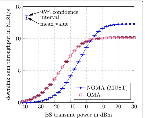
Fig. 8User assignment for the NOMA simulation scenario
user’s link. The setup here corresponds to the NOMA scenario file in the simulator package, which is sum-marized in Table 6. For the power allocation, we fix it to the second power ratio out of the three ratios that are defined in the standard (i.e., non adaptive), as it lies in the middle between the other two. Furthermore, to show the operation of NOMA with MIMO, we con-sider a 2× 2 spatial multiplexing configuration for all the users.
Table 6The simulation parameters for the NOMA example scenario
Parameter Value
Cells OMA NOMA
Number of users 2 4 (2 strong, 2 cell-edge)
Path-loss 80, 90 dB Strong: 80, 90 dB, cell-edge: 110, 115 dB
NOMA receiver - ML
MUST power-ratio - Fixed (second ratio)
Bandwidth 1.4 MHz (72 subcarriers)
Waveform/coding OFDM, LDPC
MIMO mode 2×2 CLSM
Modulation/code rate Adaptive (CQI based)
Feedback delay No delay (ideal)
Channel model Pedestrian A
In Fig. 9, the downlink sum-throughput for both the OMA and NOMA cells versus the transmit power of the BSs is plotted. When the transmit power of the BS is low, the user with the small power allocation is heavily affected by the noise, and therefore, a degradation of the sum-throughput compared to the OMA cell is expected. This is indeed what we see in the figure for transmit pow-ers below 3.2 dBm. However, once the transmit power is sufficiently high, the receiver is able to detect its signal more reliably, and the interference suppression is carried out more effectively, leading to a considerable gain in the throughput. An improvement of approximately 20% is observed at the transmit power of 15 dBm. This corre-sponds to the SNRs of 51.6 dB and 41.6 dB for the strong users, and 21.6 dB and 16.6 dB for the weak ones. The SNR here is with respect to the total superimposed received signal. We observe that MUST allows the BS to support more users in the downlink, and this, combined with a sufficiently high transmit power, leads to an improved spectral efficiency.
5.4 Channel coding for short blocks
For future 5G uRLLC and mMTC scenarios, the study of forward error correction channel codes for short block lengths in combination with low code rates is required [79, 80]. The main focus of the 5G NR standardization within Release 15 is on the eMBB use-case. Here, 3GPP already agreed to adopt Polar codes for the eMBB con-trol channels of the NR air interface, whereas LDPC codes will be employed for the corresponding data chan-nels [34]. Within Release 16 and beyond, the focus of standardization shifts towards uRLLC and mMTC, where final decisions on employed coding schemes are yet to be
Table 7The simulation parameters of the channel coding for short block lengths example
Parameter Value
Channel code Convolutional Turbo LDPC Polar
Decoder MAX-Log-MAP Linear-Log-MAP PWL-Min-Sum CRC-List-SC
Iterations/list size - 16 32 32
Block length 64 bits (48 info + 16 CRC)
Code rate 1/6
Modulation 4 QAM
Channel AWGN
Four channel codes are compared for the same short block length
made. We therefore consider in our example such uRLLC and mMTC scenarios and evaluate the performance of different channel coding schemes (convolutional, turbo, LDPC, and polar codes) for short block length and low code rate transmission. For this purpose, we require com-plete freedom in setting the parameters of the block length and code rate. Thanks to the modular structure of the simulator, we can use the channel coding object in a standalone fashion, thus eliminating the restrictions imposed by the other parts of the transmission chain, such as the number of scheduled resources or the tar-get code rate for the given channel conditions. Table 7 lists the simulation parameters of our setup. We consider here a short block length of 64 bits (including the CRC) and a low code rate of 1/6. Due to numerical stability and complexity reasons [81], approximate decoding algo-rithms are employed in practice. Because of that, we use the approximate algorithms of Linear-Log-MAP and the double PWL-Min-Sum to decode the turbo and LDPC codes, respectively. As shown in [38,41], these algorithms offer very close performance to the exact algorithms. For the convolutional code, it was shown in [82] that using the MAX-Log-MAP approximation is sufficient, as it does not have a considerable difference compared to the exact Log-MAP algorithm. For the decoding itera-tions and list size, we employ relatively large values such that the decoders operate very close to their maximum performance.
For the LDPC code, filler bits were added to the input block. This is necessary to compensate the mismatch between the chosen block length and the dimensions of the 5G NR parity check matrix. However, the addition of filler bits reduces the effective code rate, since it results in a longer output codeword. For this reason, we further puncture the output in such a way that the target length and code rate are met. This might have a negative impact on the performance of the LDPC code, as some parts of the codeword belong to the extra filler bits which are discarded after decoding. Nonetheless, by following this procedure, we guarantee that all the schemes are running with the same code rate.
Figure10shows the FER performance of the aforemen-tioned coding schemes. It can be seen that the polar code has the best performance in such setup. Namely, at the FER of 10−2, the polar code is leading by 1 dB against the LDPC code, and by 1.5 dB against the turbo and con-volutional codes. At the lower regime of the FER, the gap appears to get narrower. Still, the polar code remains the clear winner. This makes it an attractive choice for the scenarios of short block length. However, other fac-tors which are not considered here, such as the decoding latency or hardware implementation aspects, influence the choice of the coding scheme as well. The results presented in this section can be reproduced by running theshortBlockChannelCodingscript included in the sim-ulator package.
6 Conclusions
For the evolution of mobile communications from LTE to 5G and beyond, an LL simulation is an important
tool, enabling research and development of advanced PHY methods. In this contribution, we introduce the Vienna 5G LL Simulator, which is freely available for researchers to support research and enhance reproducibility. We give a general overview of the Vienna 5G LL Simulator, while further supporting documents and details are available at [2]. Further, to outline the overall functionality, exam-ples for specific features are provided, which are included in the simulators download package for increased repro-ducibility. Our simulator supports standard compliant simulation scenarios and parameter settings, according to current communication specifications such as LTE or 5G NR. Further, versatile functionality in terms of PHY procedures and methods also allows simulation and inves-tigation of potential candidate PHY schemes beyond 5G. The flexible and modular implementation additionally allows for easy augmentation of the simulator, e.g., imple-mentation of additional features, making it a valuable tool for mobile communications research.
Abbreviations
3GPP: 3rd Generation Partnership Project; AMC: Adaptive modulation and coding; AWGN: Additive white Gaussian noise; BER: Bit error ratio; BLER: Block error ratio; BS: Base station; CLSM: Closed loop spatial multiplexing; CP: Cyclic prefix; CP-OFDM: Cyclic prefix OFDM; CQI: Channel quality indicator; CRC: Cyclic redundancy check; CSI: Channel state information; eMBB: Enhanced mobile broadband; FBMC: Filter-bank multicarrier; FER: Frame error ratio; FFT: Fast Fourier transform; f-OFDM: Filtered OFDM; ICI: Intercarrier interference; IFFT: Inverse fast Fourier transform; ISI: Intersymbol interference; IUI: Inter-user interference; LDPC: Low-density parity-check; LL: Link level; LTE: Long Term Evolution; MCS: Modulation and coding scheme; MIMO: Multiple-input multiple-output; ML: Maximum likelihood; MMSE: Minimum mean squared error; mMTC: Massive machine-type communication; mmWave: Millimeter wave; MUST: Multi-user superposition transmission; NOMA: Non-orthogonal multiple access; NR: New radio; OFDM: Orthogonal frequency division multiplexing; OLSM: Open loop spatial multiplexing; OMA: Orthogonal multiple access; OOB: Out of band; PDP: Power delay profile; PHY: Physical layer; PMI: Precoding matrix indicator; QAM: Quadrature amplitude modulation; RAN: Radio access network; RI: Rank indicator; rms: Root mean squared; SC: Successive cancellation; SINR: Signal to interference and noise ratio; SL: System level; SNR: Signal-to-noise ratio; TDL: Tapped delay line; TWDP: Two-wave with diffuse power; UFMC: Universal filtered multicarrier; uRLLC: Ultra-reliable and low-latency communication; VCCS: Vienna Cellular Communications Simulators; WiMAX: Worldwide interoperability for microwave access; WOLA: Weighted overlap and add; ZP: zero prefix
Funding
This work has been funded by the Christian Doppler Laboratory for Dependable Wireless Connectivity for the Society in Motion. The financial support by the Austrian Federal Ministry for Digital and Economic Affairs and the National Foundation for Research, Technology and Development is gratefully acknowledged. The authors acknowledge the TU Wien University Library for financial support through its Open Access Funding Programme.
Availability of data and materials
All data and results presented in this manuscript are reproducible by employing the Vienna 5G Link Level Simulator available under an academic use license free of charge at [2].
Authors’ contributions
SP performed the literature review on existing LL simulators and contributed to the part on multi-link simulation of the manuscript and via implementation. BT contributed towards channel coding methods and the concept of NOMA in terms of the manuscript and implementation. LM contributed in the direction of modulation and flexible numerology to the manuscript and via
implementation. MM implemented MIMO transmissions in combination with feedback and contributed to the corresponding parts of the manuscript. KK contributed to the section on channel models and implemented the TWDP fading model. RN started the implementation of the simulator and
contributed to the part on modulation methods. SS supervises the simulator’s development. MR initiated the simulator project and supervises the research. All authors read and approved the final manuscript.
Competing interests
The authors declare that they have no competing interests.
Publisher’s Note
Springer Nature remains neutral with regard to jurisdictional claims in published maps and institutional affiliations.
Received: 24 April 2018 Accepted: 29 August 2018
References
1. C. Mehlführer, J. C. Ikuno, M. Simko, S. Schwarz, M. Rupp, The Vienna LTE simulators — Enabling Reproducibility in Wireless Communications Research. EURASIP J. Adv. Sig. Process (JASP) special issue on Reproducible Research.2011(1), 1–14 (2011)
2. Institute of Telecommunications, TU Wien: Vienna Cellular
Communications Simulators.www.tc.tuwien.ac.at/vccs/. Accessed 12 Apr 2018
3. M. Rupp, S. Schwarz, M. Taranetz. 1st edn., inSignals and Communication Technology. The Vienna LTE-Advanced Simulators: Up and Downlink, Link and System Level Simulation (Springer, Singapore, 2016).https://doi.org/ 10.1007/978-981-10-0617-3
4. J. C. Ikuno, M. Wrulich, M. Rupp, inIEEE Vehicular Technology Conference (VTC Spring). System level simulation of LTE networks (IEEE, Taipei, 2010) 5. M. Taranetz, T. Blazek, T. Kropfreiter, M. K. Müller, S. Schwarz, M. Rupp,
Runtime precoding: Enabling multipoint transmission in LTE-advanced system level simulations. IEEE Access.3, 725–736 (2015)
6. E. Zöchmann, S. Schwarz, S. Pratschner, L. Nagel, M. Lerch, M. Rupp, Exploring the physical layer frontiers of cellular uplink. EURASIP J. Wirel. Commun. Netw.2016(1), 1–18 (2016). https://doi.org/10.1186/s13638-016-0609-1
7. S. Schwarz, J. C. Ikuno, M. Simko, M. Taranetz, Q. Wang, M. Rupp, Pushing the limits of LTE: A survey on research enhancing the standard. IEEE Access.1, 51–62 (2013).https://doi.org/10.1109/ACCESS.2013.2260371 8. L. Lu, G. Y. Li, A. L. Swindlehurst, A. Ashikhmin, R. Zhang, An overview of massive MIMO: Benefits and challenges. IEEE J. Sel. Top. Sign. Process. 8(5), 742–758 (2014)
9. E. Larsson, O. Edfors, F. Tufvesson, T. Marzetta, Massive MIMO for next generation wireless systems. IEEE Commun. Mag.52(2), 186–195 (2014) 10. H. Ji, Y. Kim, J. Lee, E. Onggosanusi, Y. Nam, J. Zhang, B. Lee, B. Shim,
Overview of full-dimension MIMO in LTE-Advanced pro. IEEE Commun. Mag.55(2), 176–184 (2017)
11. A. A. Zaidi, R. Baldemair, H. Tullberg, H. Bjorkegren, L. Sundstrom, J. Medbo, C. Kilinc, I. D. Silva, Waveform and numerology to support 5G services and requirements. IEEE Commun. Mag.54(11), 90–98 (2016) 12. P. Guan, D. Wu, T. Tian, J. Zhou, X. Zhang, L. Gu, A. Benjebbour, M.
Iwabuchi, Y. Kishiyama, 5G field trials: OFDM-based waveforms and mixed numerologies. IEEE J. Sel. Areas Commun.35(6), 1234–1243 (2017) 13. K. S. Ali, H. Elsawy, A. Chaaban, M. S. Alouini, Non-orthogonal multiple
access for large-scale 5G networks: Interference aware design. IEEE Access.5, 21204–21216 (2017)
14. Z. Ding, X. Lei, G. K. Karagiannidis, R. Schober, J. Yuan, V. K. Bhargava, A survey on non-orthogonal multiple access for 5G networks: Research challenges and future trends. IEEE J. Sel. Areas Commun.35(10), 2181–2195 (2017)
15. R. W. Heath, N. González-Prelcic, S. Rangan, W. Roh, A. M. Sayeed, An overview of signal processing techniques for millimeter wave MIMO systems. IEEE J. Sel. Top. Signal Proc.10(3), 436–453 (2016)
17. S. Schwarz, M. Rupp, Exploring coordinated multipoint beamforming strategies for 5G cellular. IEEE Access.2, 930–946 (2014).https://doi.org/ 10.1109/ACCESS.2014.2353137
18. B. Clerckx, H. Joudeh, C. Hao, M. Dai, B. Rassouli, Rate splitting for MIMO wireless networks: A promising PHY-layer strategy for LTE evolution. IEEE Commun. Mag.54(5), 98–105 (2016)
19. N. Zhao, F. R. Yu, M. Jin, Q. Yan, V. C. M. Leung, Interference alignment and its applications: A survey, research issues, and challenges. IEEE Commun. Surv. Tutorials.18(3), 1779–1803 (2016)
20. G. Piro, L. A. Grieco, G. Boggia, F. Capozzi, P. Camarda, Simulating LTE cellular systems: An open-source framework. IEEE Trans. Veh. Technol. 60(2), 498–513 (2011)
21. D. Bültmann, M. Mühleisen, K. Klagges, M. Schinnenburg, inEuropean Wireless Conference. openWNS - open wireless network simulator (IEEE, 2009), pp. 205–210
22. T. Domínguez-Bolaño, J. Rodríguez-Piñeiro, J. A. García-Naya, L. Castedo, inInternational Workshop on Link-and System Level Simulations (IWSLS). The GTEC 5G link-level simulator (IEEE, 2016), pp. 1–6
23. T. R. Henderson, M. Lacage, G. F. Riley, C. Dowell, J. Kopena, Network simulations with the ns-3 simulator. SIGCOMM Demonstration.14(14), 527 (2008)
24. G. Piro, N. Baldo, M. Miozzo, inProceedings of the 4th International ICST Conference on Simulation Tools and Techniques. An LTE module for the ns-3 network simulator (ICST (Institute for Computer Sciences, Social-Informatics and Telecommunications Engineering), 2011), pp. 415–422
25. M. Mezzavilla, S. Dutta, M. Zhang, M. R. Akdeniz, S. Rangan, inProceedings of the 18th ACM International Conference on Modeling, Analysis and Simulation of Wireless and Mobile Systems. 5G mmwave module for the ns-3 network simulator (ACM, 2015), pp. 283–290
26. M. Mezzavilla, M. Zhang, M. Polese, R. Ford, S. Dutta, S. Rangan, M. Zorzi, End-to-end simulation of 5G mmWave networks. arXiv preprint arXiv:1705.02882 (2017)
27. N. Nikaein, M. K. Marina, S. Manickam, A. Dawson, R. Knopp, C. Bonnet, OpenAirInterface: A flexible platform for 5G research. ACM SIGCOMM Comput. Commun. Rev.44(5), 33–38 (2014)
28. S. Jaeckel, L. Raschkowski, K. Börner, L. Thiele, QuaDRiGa: A 3-D multi-cell channel model with time evolution for enabling virtual field trials. IEEE Trans. Antennas Propag.62(6), 3242–3256 (2014)
29. M. K. Samimi, T. S. Rappaport, 3-D millimeter-wave statistical channel model for 5G wireless system design. IEEE Trans. Microw. Theory Tech. 64(7), 2207–2225 (2016)
30. S. Sun, G. R. MacCartney, T. S. Rappaport, inInternational Conference on Communications (ICC). A novel millimeter-wave channel simulator and applications for 5G wireless communications (IEEE, 2017), pp. 1–7 31. 3rd Generation Partnership Project (3GPP), Evolved Universal Terrestrial
Radio Access (E-UTRA) physical channels and modulation. TS 36.211, 3rd Generation Partnership Project (3GPP) (2015). 3rd Generation Partnership Project (3GPP)
32. 3rd Generation Partnership Project (3GPP), Technical Specification Group Radio Access Network; NR; Physical channels and modulation. TS 38.211, 3rd Generation Partnership Project (3GPP) (2017). 3rd Generation Partnership Project (3GPP)
33. 3rd Generation Partnership Project (3GPP), Evolved Universal Terrestrial Radio Access (E-UTRA); Multiplexing and channel coding. TS 36.212, 3rd Generation Partnership Project (3GPP) (2017). 3rd Generation Partnership Project (3GPP)
34. 3rd Generation Partnership Project (3GPP), Technical Specification Group Radio Access Network; NR; Multiplexing and channel coding. TS 38.212, 3rd Generation Partnership Project (3GPP) (2017). 3rd Generation Partnership Project (3GPP)
35. B. Tahir, M. Rupp, in24th International Conference on Telecommunications (ICT). New construction and performance analysis of polar codes over AWGN channels, (2017), pp. 1–4.https://doi.org/10.1109/ICT.2017. 7998250
36. L. Bahl, J. Cocke, F. Jelinek, J. Raviv, Optimal decoding of linear codes for minimizing symbol error rate (Corresp.) IEEE Trans. Inf. Theory.20(2), 284–287 (1974).https://doi.org/10.1109/TIT.1974.1055186
37. W. Koch, A. Baier, inGlobal Telecommunications Conference (GLOBECOM). Optimum and sub-optimum detection of coded data disturbed by time-varying intersymbol interference [applicable to digital mobile radio
receivers], (1990), pp. 1679–16843.https://doi.org/10.1109/GLOCOM. 1990.116774
38. J.-F. Cheng, T. Ottosson, in51st Vehicular Technology Conference Proceedings. Linearly approximated log-MAP algorithms for turbo decoding, vol. 3, (2000), pp. 2252–22563.https://doi.org/10.1109/VETECS. 2000.851673
39. D. J. C. MacKay, Good error-correcting codes based on very sparse matrices. IEEE Trans. Inf. Theory.45(2), 399–431 (1999).https://doi.org/10. 1109/18.748992
40. J. Chen, A. Dholakia, E. Eleftheriou, M. P. C. Fossorier, X.-Y. Hu, Reduced-complexity decoding of LDPC codes. IEEE Trans. Commun.53(8), 1288–1299 (2005).https://doi.org/10.1109/TCOMM. 2005.852852
41. M. M. Mansour, N. R. Shanbhag, High-throughput LDPC decoders. IEEE Trans. Very Large Scale Integr. (VLSI) Syst.11(6), 976–996 (2003).https:// doi.org/10.1109/TVLSI.2003.817545
42. P. Radosavljevic, A. de Baynast, J. R. Cavallaro, inConference Record of the Thirty-Ninth Asilomar Conference on Signals, Systems and Computers. Optimized message passing schedules for LDPC decoding, (2005), pp. 591–595.https://doi.org/10.1109/ACSSC.2005.1599818 43. E. Arikan, Channel Polarization: A Method for Constructing
Capacity-Achieving Codes for Symmetric Binary-Input Memoryless Channels. IEEE Trans. Inf. Theory.55(7), 3051–3073 (2009).https://doi.org/ 10.1109/TIT.2009.2021379
44. I. Tal, A. Vardy, inIEEE International Symposium on Information Theory Proceedings. List decoding of polar codes, (2011), pp. 1–5.https://doi.org/ 10.1109/ISIT.2011.6033904
45. 3rd Generation Partnership Project (3GPP), Technical Specification Group Radio Access Network; Study on New Radio (NR) access techology. TR 38.912, 3rd Generation Partnership Project (3GPP) (2017). 3rd Generation Partnership Project (3GPP)
46. R. Nissel, S. Schwarz, M. Rupp, Filter bank multicarrier modulation schemes for future mobile communications. IEEE J. Sel. Areas Commun. 35(8), 1768–1782 (2017)
47. F. Schaich, T. Wild, in16th International Workshop on Signal Processing Advances in Wireless Communications (SPAWC). Subcarrier spacing-a neglected degree of freedom? (IEEE, 2015), pp. 56–60
48. 3rd Generation Partnership Project (3GPP), Evolved Universal Terrestrial Radio Access (E-UTRA); LTE physical layer; General description. TS 36.201, 3rd Generation Partnership Project (3GPP) (2018). 3rd Generation Partnership Project (3GPP)
49. R. Zayani, Y. Medjahdi, H. Shaiek, D. Roviras, inIEEE Globecom Workshops (GC Wkshps). WOLA-OFDM: a potential candidate for asynchronous 5G (IEEE, 2016), pp. 1–5
50. F. Schaich, T. Wild, in6th International Symposium on Communications, Control and Signal Processing (ISCCSP). Waveform contenders for 5G—OFDM vs. FBMC vs. UFMC (IEEE, 2014), pp. 457–460
51. V. Vakilian, T. Wild, F. Schaich, S. ten Brink, J.-F. Frigon, inIEEE Globecom Workshops (GC Wkshps). Universal-filtered multi-carrier technique for wireless systems beyond LTE (IEEE, 2013), pp. 223–228
52. S. Geng, X. Xiong, L. Cheng, X. Zhao, B. Huang, in6th International Symposium on Microwave, Antenna, Propagation, and EMC Technologies (MAPE). UFMC system performance analysis for discrete narrow-band private networks (IEEE, 2015), pp. 303–307
53. S. Venkatesan, R. A. Valenzuela, inInternational Conference on
Communications (ICC). OFDM for 5G: Cyclic prefix versus zero postfix, and filtering versus windowing (IEEE, 2016), pp. 1–5
54. J. Abdoli, M. Jia, J. Ma, in16th International Workshop on Signal Processing Advances in Wireless Communications (SPAWC). Filtered OFDM: A new waveform for future wireless systems (IEEE, 2015), pp. 66–70 55. R. Nissel, M. Rupp, R. Marsalek, inIEEE International Workshop on Signal
Processing Advances in Wireless Communications (SPAWC). FBMC-OQAM in doubly-selective channels: A new perspective on MMSE equalization, (Sapporo, 2017)
56. L. Marijanovi´c, S. Schwarz, M. Rupp, inInternational Symposium on Wireless Communication Systems (ISWCS). MMSE equalization for FBMC transmission over doubly-selective channels (IEEE, 2016), pp. 170–174