Abstract—The research on two-wheeled inverted pendulum (T-WIP) mobile robots or commonly known as balancing robots have gained momentum over the last decade in a number of robotic laboratories around the world. This paper describes the hardware design of such a robot. The objective of the design is to develop a T-WIP mobile robot as well as MATLAB interfacing configuration to be used as flexible platform comprises of embedded unstable linear plant intended for research and teaching purposes. Issues such as selection of actuators and sensors, signal processing units, MATLAB Real Time Workshop coding, modeling and control scheme will be addressed and discussed. The system is then tested using a well-known state feedback controller to verify its functionality.
Keywords—Embedded System, Two-wheeled Inverted Pendulum Mobile Robot.
I. INTRODUCTION
NVERTED pendulum has been the subject of numerous studies in automatic control since the forties. In this paper, the development of the theme inspired by the well known Segway robot is described. This kind of robots has induced a lot of interest recently [1]. This is due to the fact that it provides rich opportunities for application of control design, signal processing, distributed control systems and consideration of real time constraint for implementation issues. A scaled down prototype of a Digital Signal Processor controlled two–wheeled vehicle called JOE based on the inverted pendulum with weights attached to the system to simulate a human driver was considered in [2]. A linear state space controller utilizing sensory information from a gyroscope and motor encoders is used to stabilize the system. With small carts built utilizing this technology allows humans to travel short distances in a small area or factories instead of using car or buggies which is more polluting [3].
The trajectory control for this type of robot was successfully implemented in two dimensional by [4]. The proposed trajectory control algorithm can make the robot move autonomously, although quite slowly. The work was further extended in [5] where the robot is assumed to receive similar input on both wheels and the mathematical modeling is represented in one dimensional plane system. Based on successful result in [5], similar work has been reported using LQR controller [6]. The dynamic model of a two-wheeled inverted pendulum is analyzed from controllability and
The authors are with the Faculty of Electrical Engineering, Universiti Teknologi Malaysia, Johor Bahru, 81310 Malaysia (e-mail: [email protected]).
Special thanks to Universiti Teknologi Malaysia for the financially support toward this research.
feedback linearizability point of view by [7]. The strong accessibility condition is checked and the maximum relative degree of the system is found. A general discussion on motion control of T-WIP is done by [8].
The attitude is difficult to detect by simply using the signals from sensor. The integration of rate gyroscope signal has contributed the problem of drift. The problem solve using an observer that considering internal dynamic of the system [9]. The estimation and control algorithm of the posture using the adaptive observer is proposed by [10]. The presented algorithm did not consider movement on the two dimensional plane and the robot also was not autonomous and connected by wires with ground computer. A variable structure controller for two wheels inverted pendulum mobile robot is proposed for tracking to desire trajectories by [11]. However this work is consider the robot has caster to support the robot body from falling down. As a view point of tilt-up control, [12] doing research on gyroscopically in stabilized the robot, and [13] have studied inverted systems. The research is still open to explore for new controller development. A common sense solution to the stability problem and applied it to human postural problem is proposed by [14]. However the approximate profile of terrain can be an uncertain.
The remaining of the paper is organized as follows: Section II treats on hardware design, particularly in the selection of sensors and their associated algorithms Section III describes the mathematical modeling of the robot. Section IV addressed the controller design and their simulation results. Section V presents the MATLAB interfacing configuration. Finally the verification of the controller using real time implementation is shown experimentally. Results of the real time implementation will be illustrated in details.
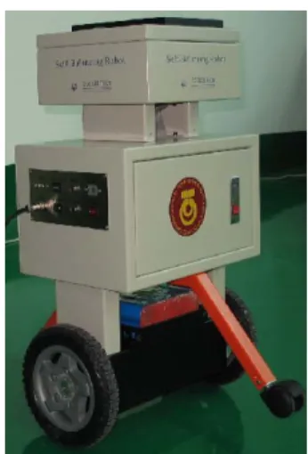
Fig. 1 The prototype T-WIP mobile robot
S. W. Nawawi, M. N. Ahmad, and J. H. S. Osman
Real-Time Control of a Two-Wheeled Inverted
Pendulum Mobile Robot
II. HARDWARE DEVELOPMENT
Fig. 1 shows the prototype design of the robot. The robot is equipped with two servo drives for actuation, a Gyroscope for measuring angle and angular velocity of pendulum body, and encoders for measuring the position of the wheels. Signal processing and control algorithm are distributed among the three microprocessors. Two of them are used for servo drives while the other one is used for stabilizing control. Although this kind of layout enables hierarchical control design, it also complicates implementation, since processor communication must also be considered. The T-WIP mobile robot is composed of a chassis carrying a DC motor coupled to a planetary gearbox for each wheel, the DSP board used to implement the controller, the power amplifiers for the motors, the necessary sensors to measure the vehicle’s states. The battery is bolted inside the body casing and it significantly represents 30% of the total robot mass. The wheels of the vehicle are directly coupled to the output shaft of the gearboxes. The robot is control by applying a torque CR and
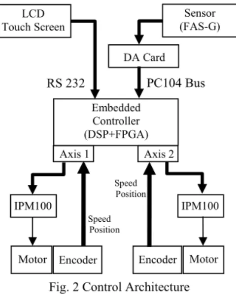
CL to the right and left wheels respectively. Fig. 2 illustrates
the block diagram of the control architecture of the system.
The controller is implemented on an Embedded DSP board [15]. It is a standalone motion controller based on combination of embedded PC104 main board of X86, motion control board, terminal board in one structure, and thus has the advantages of smaller dimension, less wiring, real time capability and higher reliability. It is easy to upgrade, install and maintain, and thus increase the reliability of the robot to operate under adverse industrial environments, such as humid, dust, and vibration.
Conventional inclinometers, or analog tilt sensors, typically exhibit slow response and cannot be used to track dynamic angular motion. On the other hand, angular rate sensors can be used to measure fast rotations, but they suffer from significant drift and error accumulation over time. Inertial measurement units (IMU’s) can be used to overcome these limitations, but these are relatively large and expensive. As such, the FAS-G sensor from MicroStrain is used as the gyro sensor [16].
Employing micro-electromechanical (MEM) sensors, FAS-G consists of a combination of two low pass filtered
accelerometers and one piezo-ceramic gyro. The angular rate signal is integrated internally over time and compared to the accelerometer signal to eliminate drift. The gyro output signal is an analog voltage between 0 and 5 volts corresponding to the angle of tilt. This signal is read from the Data Acquisition Card and the result is passed to PC by PC104 data bus. It was calculated that one ADC count corresponds to an incremental tilt of 0.08789º. A secondary angular rate signal is also generated by means of software computation. Fig. 3 show angle of rotation for a two-wheeled inverted pendulum mobile robot in two dimensional plane.
Fig. 3 Angle of Rotational
Both geared servo motor needs to generate a very high torque. To achieve this, the IPM100 is used as the motor driver. It is basically a 36V, 3A fully digital intelligent servo drive based on the DSP controller technology. It is also embedded with the high level Technosoft Motion Language (TML) and therefore offers a flexible, compact and easy to implement solution for single or multi-axis applications with brushless and DC motors.
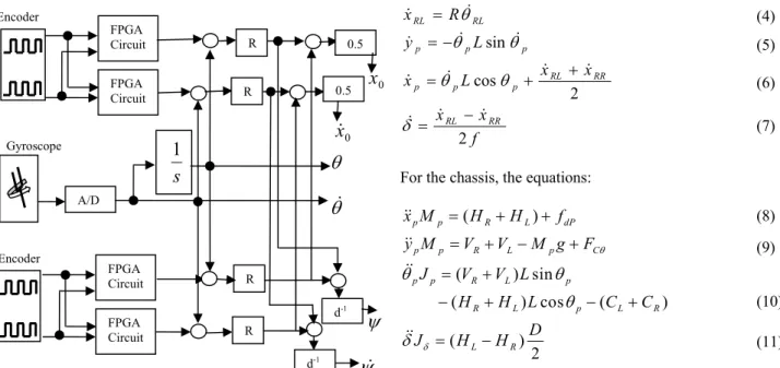
To provide information about T-WIP states for control purposes, two incremental encoders and a rate gyroscope are interfaced together as shown in Fig. 4. All the interfacing is based on control structure of embedded system seen in Fig. 2 above. Straight line position and speed as wells as yaw angle and rate can be determined from the angle rotation of the two wheels (θRR and θRR) with respect to the gravity. The relation
of these angles with pitch angle, θP and the body angle, θRPL
and θRPR can be referred in Fig. 3. The embedded controller
has task to monitor all feedback coming from incremental encoder. Then process the feedback to make sure T-WIP is balance at it equilibrium point. The command to embedded controller is given by IPC using C language interfacing in the Real Time Workshop of MATLAB. The IPC is running online or at the same time with system to show the real time result according to the output response needed.
Motor Encoder Encoder Motor
IPM100 IPM100 Embedded Controller (DSP+FPGA) Axis 1 Axis 2 DA Card LCD Touch Screen Sensor (FAS-G) RS 232 PC104 Bus Speed Position
Fig. 2 Control Architecture Speed Position P
θ
RPRθ
RPLθ
RRθ
θ
RL x yFig. 4 Interface between sensor signals and the Embedded DSP board
III. MATHEMATICAL MODELING
The dynamic performance of a balancing robot depends on the efficiency of the control algorithms and the dynamic model of the system [17]. By adopting the coordinate system shown in Fig. 5 using Newtonian mechanics, it can be shown that the dynamics of the T-WIP mobile robot under consideration is governed by the following motion equations (1-15) [2],[18]. The coordinate system for the robot is depicted in Fig. 5.
Fig. 5 Coordinate system of the T-WIP
For left hand wheel (analogous for right hand wheel):
f x x x x L x L y R x RR RL RR RL p p p p p p RL RL 2 2 cos sin − = + + = − = =
δ
θ
θ
θ
θ
θ
For the chassis, the equations:
( ) ( ) sin ( ) cos ( ) ( ) 2 p p R L dP p p R L p C p p R L p R L p L R L R x M H H f y M V V M g F J V V L H H L C C D J H H θ δ
θ
θ
θ
δ
= + + = + − + = + − + − + = −where HTL, HTR, HL, HR, VTL, VTR, VL, VR represent reaction
forces between the different free bodies. The robot parameters are as tabulated in Table I.
TABLEI PARAMETER OF T-WIP
Symbol Parameter Value [Unit]
r
x Straight line position [m]
p
θ Pitch angle [rad]
δ Yaw angle [rad]
, RL RR
J J Moment of inertia of the rotating masses with respect to the z axis
[kgm2] r
M Mass of rotating masses connected to the left and right wheel .
RL RR r
M =M =M
0.420 [kg] p
J Moment of inertia of the chassis with respect to z axis 0.28 [kgm2]
Jδ Moment of inertia of the chassis with respect to the y axis 1.12 [kgm2] p
M Mass of Body 21.0 [kg]
R Radius of wheel 0.106[m]
L Distance between the z axis and the center of gravity of vehicle 0.4 [m]
D Lateral distance between the contact patches of the wheels. 0.4[m] r
y Shift position of the wheel with respect to the y axis.
p
x Shift position of the chassis with respect to the x axis.
g Gravity constant 9.8 [ms-2]
L
C ,CR Input torque for right and left wheels accordingly
Equations (1)-(11) can be represented in the state-space form as:
u
x
g
x
f
t
x
(
)
=
(
)
+
(
)
wherex∈ℜn,u∈ℜmare respectively the state and the control. f(x) is nonlinear dynamic function matrix and g(x) is
(12) (1) (2) (3) (5) (6) (7) (8) (9) (10) (11) R H C J g M V V M y f f H H M x TL L RL RL r L TL r RL dRR dRL L TL r RL − = − − = + + − = θ ( ) Encoder Encoder Gyroscope FPGA Circuit FPGA Circuit FPGA Circuit FPGA Circuit A/D
s
1
R R R R 0.5 d-1 0.5 d-1 0x
0x
θ
θ
ψ
ψ
(4)nonlinear input function matrix. The state, x of the system is defined as:
[ , , , , , ]'
r r p px
=
x x
θ θ δ δ
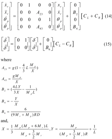
Modifying the equations above and then linearizing the result around the operating point (θp=0, xr=0, δ=0) and de-coupling,
the system’s state space equations can be written in matrix form as:
[
]
23 2 43 4 0 1 0 0 0 0 0 0 0 0 0 1 0 0 0 0 r r r r L R p p p p x x x A x B C C A Bθ
θ
θ
θ
⎡ ⎤ ⎡ ⎤⎡ ⎤ ⎡ ⎤ ⎢ ⎥ ⎢ ⎥⎢ ⎥ ⎢ ⎥ ⎢ ⎥ =⎢ ⎥⎢ ⎥+⎢ ⎥ + ⎢ ⎥ ⎢ ⎥⎢ ⎥ ⎢ ⎥ ⎢ ⎥ ⎢ ⎥⎢ ⎥ ⎢ ⎥ ⎢ ⎥ ⎣ ⎦⎢ ⎥ ⎣ ⎦ ⎣ ⎦ ⎣ ⎦[
]
60
0 1
0 0
C
LC
RB
δ
δ
δ
δ
⎡ ⎤
⎡
⎤ ⎡ ⎤
⎡ ⎤
=
+
−
⎢ ⎥
⎢
⎥ ⎢ ⎥
⎢ ⎥
⎣
⎦ ⎣ ⎦ ⎣ ⎦
⎣ ⎦
where 23 43 2 4 6 4 (1 ) 3 4 1 ( ) 3 6 (9 ) p p p r p M A g L X gM A X L Y B X M L Y B X B M M R D = − = = − = − = + and, ( 6 ) 1 1 , 3 3 3 ( ) 2 2 p p r p p r p r M M M L M X Y L M M M M R + = = + + +For simplicity, the details of equation (14) and (15) are not shown here and can be found elsewhere [19]. The T-WIP balancing model, namely equation (14) will be used through out this work consequently.
IV. CONTROLLER DESIGN
System performance (i.e. reaction to disturbance forces, tracking of driver input, etc.) is driven by the pole placement controller. In order to test the T-WIP performance, pole-placement controllers with different poles has been applied.
For a chosen pole placement, the controller’s gains were calculated and implemented on the embedded board. T-WIP was then tested with the configuration and the response is then recorded by the control system. One of the tests conducted consist of an impulse disturbance force applied to a position above the center of gravity. The energy transmitted with a falling weight amounted to about 1.2 J.
Issues like damping ratio and settling time could be clearly identified on the recorded responses and permitted an efficient fine-tuning of the system. Fig. 6 shows the system’s response to the above mentioned test with the initial pole placement chosen at pole [-1.5,-1.5,-0.5-3i,-0.5+3i]. Note the pronounced
oscillation of the system which indicates too weak damping. Increasing the damping ratio when change the pole to [-1.5-i,-1.5+i,-3.5-5i,-3.5+5i] give the result as shown in Fig. 7. It can be seen that the response improves significantly. Now it has a harmonious catching of the disturbance force. When the force hit T-WIP, it causes the pendulum to fall forwards (θp<0).
The control system accelerates the wheels in a positive direction to catch this fall and ultimately make the pendulum fall in the other direction. A negative torque is then applied, moving the vehicle back to its original position and getting the pendulum back in an upright position. The controller task is to make sure that:
θp∈ As =
{
θp <θm <π /2}
, for a given θm > 0This is a physically meaningful problem because using these reference commands, one can safely follow a motion plan. The essential idea to use the pitch angle θp as a gas pedal for
vehicle and use it to accelerate and decelerate until the specified speed is attained.
Fig. 6 Initial pole placement of the “pendulum” system and associated response to an impulse disturbance force (energy
transmitted≈1.2 J) applied to the pendulum
Fig. 7 Improved pole placement of the “pendulum” system and associated response to an impulse disturbance force (energy
transmitted≈1.2 J) applied to the pendulum
(13)
(14)
(15)
Another issue that has been addressed during testing is drivability. In order to successfully improve drivability, it was characterized based on two criteria. First criteria are readouts of the system’s reaction to a ramp shaped speed input and second criteria are the way different drivers felt about T-WIP handling.
Combining the driver’s feelings with the readouts of system behavior allowed further improvement of T-WIP control system. Fig. 8 shows the system’s response to a velocity ramp input with the final pole placement chosen. Note that the maximum acceleration possible is lower than the maximum deceleration. Due to the motor’s speed-current characteristics, a high torque cannot be obtained when operating at high speeds. However, this is exactly what is necessary to get the vehicle back into an upright position at the end of the acceleration phase. Deceleration demands maximum torque at low speeds so a steeper ramp is therefore possible.
Increasing performance with the pole placement chosen can be achieved by moving the poles further to the left, thus making the system faster [20]. Backlash as well the maximum torque that can be transmitted to the ground (grip) prevent tuners from moving the poles past a certain limit. The used of an adaptive pole placement and nonlinear controller (depending on the system’s state) would enable further improvements to the system.
Fig. 8 Reaction to a ramp shaped speed input
V. MATLABINTERFACING DESIGN
The embedded control system in this work is design based on real-time workshop of MATLAB. Hence it makes the interfacing protocol between embedded controller card and MATLAB is the most pivotal. T-WIP real-time balancing will be fully carried out in the Real Time Workshop of MATLAB. Therefore it has an advantages of be intellectualized to observe the real-time results and performance of controller when be integrated with actuator. Furthermore, the controller can be redesigned expediently and repetitiously until users get a satisfactory result.
In the RTW (Real Time Workshop) of MATLAB, the special real-time kernel model replaces message processing via windows. Hence the capability of real-time mode to gets better response is good enough.
.
Fig. 9 MATLAB RTW Kernel Model
RTW builds applications from Simulink diagrams for prototyping, testing, and deploying real-time systems on a variety of target computing platforms. Users of Real-Time Workshop can direct it to generate source code that accommodates the compilers, input and output devices, memory models, communication modes, and other characteristics that their applications may require.
First step of configuration setup is to install MATLAB with Real-Time Windows Target and Visual C/C++ software. Then by using some command in Matlab, the Real-Time Windows Target kernel is activated together menu to select C compiler in MATLAB. A sampling demo of the sensor will be presented based on MATLAB RTW. In way to design an S-function block written in C Language, in which an S-S-function parameter for index of ad channels and an output should be defined. The fractional source code of GetAD.c is as follows,
#define S_FUNCTION_NAME GetAD #define NUM_PARAMS (1)
#define AD_CHANNEL _PARAM (ssGetSFcnParam(S,0))
#define AD_CHANNEL (real_T)mxGetPr(AD_CHANNEL_PARAM)[0])
After coding for GetAD.c, by using a command line in MATLAB with no errors occur, the GetAD S-function then finished generating. Then the block parameter for ad channel is configured to channel 1. Secondly another system target file GetAD.tlc need to be design which is will be saved in the same directory with GetAD.c. The main source code flow chart of GetAD.tlc is as follows:
Fig. 10 Coding flowchart for GetAD.tcl
Finish Start
Initialize the parameter Initialize the target port
Channel setting for every port define
Input/Output configuration on every channel used
For the reference purpose, the command “_outp” and “_inp” in the target file GetAD.tlc is used for sending and receiving data between embedded controller and MATLAB. The comand ctrl_byte=oxff, is used in GetAD.tlc file to make
sure the DA card will stop find online data on the PC104 bus. GetAD.tlc then compiled and be confirmed there is no error occurs.
In simulation parameter properties of GetAD.c, category need to build as Target configuration with system target file of rtwin.tlc. This configuration is used as setting for Real-time workshop in Matlab. Then the solver options and fixed step size configuration is set with sampling time 5ms.
The file is compiled after selecting “External” mode. The output of the sensor signal can be shown in Fig. 11.
Fig. 11 Angle for sampling gyro sensor
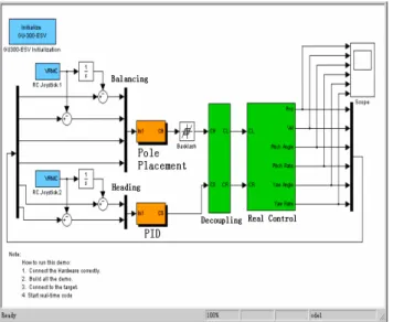
The same method is using to design other S-functions models. Finally, an interface for T-WIP in the RTW of MATLAB is extracted. Now T-WIP test bed can be used for any type of controller as long as the structure of system is same. The structure of system is shown in Fig. 12. It does consist of three main block which is Input block, controller block and Real Plant block. The input reference for speed and orientation can be replaced by desired input function as wells.
Fig. 12 Real-time control interface using Poleplacement controller for T-WIP at equilibrium
VI. EXPERIMENTAL RESULT
In order to verify the developed T-WIP hardware system, the pole-placement algorithm as designed in previous section implemented as the controller. Fig. 13 show that the responses of the system closely match the simulation result in Fig. 6 which demonstrates the complete T-WIP system is functioning well in close-loop system. From the Fig. 14, it can be shown that the output response for position, velocity, inclination angle and angular velocity of inclination is following the shape of simulation result. The steady state error of position and velocity is approximately zero. It also shows that the values of steady state error are about zero of the inclination angle and its velocity. The pole placement controller seems to be capable in term of steady state error and settling time.
Fig. 13 Real-time control result of T-WIP output response using pole placement controller
After zooming in certain area on Figure 14, it can be seen on result in Fig.18, it shown that the system is in equilibrium within small range of vibration. The chassis range of vibration is about 4x10⁻³m and the trunk vibration range is about
0.05rad.
Fig. 14 Real-time control results of vibration scale for T-WIP at equilibrium using pole placement controller
Position(m, r ad), S peed(m/s, rad/ s) A m pl itu d(m, ra d) Position Velocity Inclination Inclination rate
For further research the T-WIP will be tested with the various type nonlinear controllers. Among of them are State feedback Linearization and Sliding Mode Control.
VII. CONCLUSION
In this paper, the development of a T-WIP mobile robot system is presented. The issues of dynamical modeling, selection of actuators and sensors, MATLAB based interfacing and configuration of the embedded controller, as well as the implementation of pole placement control strategy has been addressed. The embedded control system using real-time workshop of MATLAB is confirm working well and all sensors give a good feedback signal based on the response getting from the experimental work. The results from this work show that the proposed embedded design architecture based on Matlab is capable of delivering the desired outcome.
ACKNOWLEDGMENT
The authors gratefully acknowledged the contributions of Kaustubh Pathak for work on the original version of this document.
REFERENCES
[1] Salerno, A and Angeles, J, “Nonlinear Conrollability of Quasiholonomic Mobile Robot”. Proc. IEEE ICRA, Taiwan, 2003.
[2] Grasser, F., D’Arrigo, A., Comlombi, S., and Rufer, A, ”Joe: A mobile inverted pendulum”, IEEE Trans. Electronics, vol. 49, no 1, Feb 2002, pp. 107-114.
[3] Salerno, A. and Angeles, J, “A new family of Two Wheeled Mobile Robot: Modeling and Controllability”. IEEE Transaction of Robotics, Vol. 23. No. 1, Feb 2007, pp. 169-173.
[4] Koyanagi, E. , Lida, S. and Yuta, S. ,”A wheeled inverse pendulum type self-contained mobile robot and its two-dimensional trajectory control”, Proceeding of ISMCR92, pp.891-898, 1992.
[5] Ha, Y.S. and Yuta, S, “Trajectory Tracking Control for Navigation of the Inverse Pendulum Type Self-contained Mobile Robot”. Robotic and Autonomous System, 17, 1996 pp. 65-80.
[6] Kim, Y.H., Kim, S.H., and Kwak, Y.K, “Dynamic Analysis of a Nonholonomic Two-wheeled Inverted Pendulum Robot”, Proc. of the Eighth Int. Symp. on Artificial Life and Robotics, Beppu, Oita, Japan, 24-26 January 2003, pp. 415-418.
[7] Pathak, Kaustubh. Franch, Jaume. Agrawal, Sunil K, “Velocity and position control of a wheeled inverted pendulum by partial feedback linearization“ IEEE Transactions on Robotics, v 21, n 3, June, 2005, pp. 505-513.
[8] Tsuchiya, K., Urakubo, T. and Tsujita, K., “A motion control of a Two wheeled mobile robot”, IEEE International conference on system, man and cybernetics, Tokyo Japan, 1999.
[9] Matsumoto, O., Kajita, S. and Tani, K., “Estimation and control of the attitude of a dynamic mobile robot using internal sensors”, Advance Robotic, Vol. 7, no. 2, 1993, pp159-178.
[10] Matsumoto, O., Kajita, S. and Tani, K. “Attitude estimation of the wheeled inverted pendulum using adaptive observer”, 9th Academic conference of the Robotics Society of Japan, Japan, 1991, pp 909-910. [11] Shim, H. S., Kim, J. H. and Koh, K. “Variable Structure control of
nonholonomic wheeled mobile robot”, IEEE International conference on Robotics and automation, 1995, pp 1694-1699.
[12] Au, S. K. W., Xu, Y. and Yu, W. W. K. “Control of till up motion of a single wheel robot via model based and human based controller”, Mechatronics vol 11, 2001, pp 451-473.
[13] Awtar, S. et al. “Inverted pendulum systems: rotary and arm driven- a mechatronic system design case study”, Mechatronics vol 12, 2002, pp 357-370.
[14] Deniskina, I. V., Levi, K. Y. S. and Gurfinkel, V. S. “Relative roles of the ankle and hip muscles in human postural control in the frontal plane surfing standing”, Journal of Intelligent Robot System v 27, n 3, 2001, pp 317-321.
[15] Googol Technology LTD, “All in one embedded motion controller specification”. [Online]. Available: http://www.googoltech.com
[16] “FAS-G Gyroscope Manual by Microstrian”. [Online]. Available: http://www.microstrain.com/fas-g.asp
[17] Baloh, M. and Parent, M, “Modeling and Model Verification of an intelligent self balancing two-wheeled vehicle for an autonomous urban transportation system”. Conf. Comp. Intelligence, Robotic and Autonomous systems, Singapore, Dec, 15, 2003.
[18] Pathak, Kaustubh.Agrawal, Sunil K, “Band-limited trajectory planning and tracking for certain dynamically stabilized mobile systems”, Journal of Dynamic Systems, Measurement and Control, Transactions of the ASME, v 128, n 1, March, 2006, pp 104-111.
[19] Nawawi, S.W., Ahmad, M.N. and Osman, J.H.S., “Development of Two-wheeled Inverted Pendulum Mobile Robot”, SCOReD07, Malaysia, Dec 2007, pp 153-158.
[20] Vaccaro, R. J. “Digital Control: A State-space Approach”, McGraw-Hill Inc., United State 1995.