International Journal of Science Engineering and Advance Technology,
IJSEAT, Vol 2, Issue 7, July - 2014 ISSN 2321-6905
www.ijseat.com
Page 191
Investment Casting Of Torpedo Nozzle
S.Vishwanath, S.Moulali Reddy, Pulluri Harish
MTech,
Turbo Machinery Institute of Science and Technology
Mahatma Gandhi Institute of Technology,
[email protected], [email protected] ,
Abstract - Investment Casting is also known as Lost Wax
process. Investment casting process is generally used to produce intricate and complex shaped products. The primary objective of the project work is to produce Torpedo Nozzle by investment casting. Nozzles are manufactured by investment casting process consisting of wax injection, ceramic coating, wax removal, metal casting, and finishing. The creep strength of the product should be enhanced as we go to higher temperature application. Super Alloys (Ni-based) satisfy the above condition and are hence used for the production of components used at elevated temperatures. Earlier IN 718 was used in the manufacture of Torpedo nozzles by mechanical working and machining the alloy to obtain the final product. Machining of the nozzle was difficult as it involved intricate shape internally and also as found to be eroding during its service. This alloy also can not be used above 700°C because the strengthening precipitates will coarsen. Hence, we produced the nozzles by Investment Casting process, using CM 247 to overcome the limitations of IN 718. CM 247 can withstand higher temperatures (1000°C - 1100°C) and has better mechanical properties over IN 718. The focus of this experimental work was on the several stages of investment casting process and the microstructures were also studied.
Keywords- torpedo,investmentcasting,cm 247lc,inc 718
1. INTRODUCTION A.Investment Casting
Investment (lost wax) casting is a widely used casting technique in which a pattern usually made of wax is formed by introducing a molten wax composition into a mold having the shape of the finished part and by cooling it until solidification. In the ceramic shell method, the pattern or a cluster of such patterns is/are gated to a wax sprue. Then the sprued pattern or patterns is/are invested with ceramic slurry which is then solidified to build a shell around the wax pattern. The pattern wax is then removed from the mold by melting or burning. The resulting refractory shell is further hardened by heating and filled with molten metal to produce the finished part. In this process, surface and dimensional characteristics of the pattern are transferred to
the ceramic shell and so to the final casting. (Refer to the figure1)
Fig. 1: Steps in the investment casting process
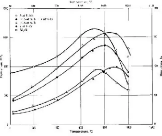
Fig. 2: Flow stress peak in gamma prime & influence of several solutes
3.1 Manufacture of Torpedo Nozzle
Investment casting of the torpedo nozzle involves the following steps:
International Journal of Science Engineering and Advance Technology,
IJSEAT, Vol 2, Issue 7, July - 2014 ISSN 2321-6905
www.ijseat.com
Page 191
Investment Casting Of Torpedo Nozzle
S.Vishwanath, S.Moulali Reddy, Pulluri Harish
MTech,
Turbo Machinery Institute of Science and Technology
Mahatma Gandhi Institute of Technology,
[email protected], [email protected] ,
Abstract - Investment Casting is also known as Lost Wax
process. Investment casting process is generally used to produce intricate and complex shaped products. The primary objective of the project work is to produce Torpedo Nozzle by investment casting. Nozzles are manufactured by investment casting process consisting of wax injection, ceramic coating, wax removal, metal casting, and finishing. The creep strength of the product should be enhanced as we go to higher temperature application. Super Alloys (Ni-based) satisfy the above condition and are hence used for the production of components used at elevated temperatures. Earlier IN 718 was used in the manufacture of Torpedo nozzles by mechanical working and machining the alloy to obtain the final product. Machining of the nozzle was difficult as it involved intricate shape internally and also as found to be eroding during its service. This alloy also can not be used above 700°C because the strengthening precipitates will coarsen. Hence, we produced the nozzles by Investment Casting process, using CM 247 to overcome the limitations of IN 718. CM 247 can withstand higher temperatures (1000°C - 1100°C) and has better mechanical properties over IN 718. The focus of this experimental work was on the several stages of investment casting process and the microstructures were also studied.
Keywords- torpedo,investmentcasting,cm 247lc,inc 718
1. INTRODUCTION A.Investment Casting
Investment (lost wax) casting is a widely used casting technique in which a pattern usually made of wax is formed by introducing a molten wax composition into a mold having the shape of the finished part and by cooling it until solidification. In the ceramic shell method, the pattern or a cluster of such patterns is/are gated to a wax sprue. Then the sprued pattern or patterns is/are invested with ceramic slurry which is then solidified to build a shell around the wax pattern. The pattern wax is then removed from the mold by melting or burning. The resulting refractory shell is further hardened by heating and filled with molten metal to produce the finished part. In this process, surface and dimensional characteristics of the pattern are transferred to
the ceramic shell and so to the final casting. (Refer to the figure1)
Fig. 1: Steps in the investment casting process
Fig. 2: Flow stress peak in gamma prime & influence of several solutes
3.1 Manufacture of Torpedo Nozzle
Pattern Making Pattern Assembly Slurry Coating Drying Dewaxing
Firing & Inspection Melting
Fettling Finished Product
Table 1: Specifications of Injection molding machine
Fig 3: Nozzle (wax) patterns
3.1.2 Pattern Assembly
Clustering of the patterns produced was done. Three different gating ratios i.e, 12mm, 15mm and 18mm were maintained while assembling the patterns. Two different clusters were prepared using the 8 patterns produced .Each contained 4 nozzle patterns.
Slurry Coating
The cluster was then coated thoroughly and dried completely before each coating. Totally 8 coatings were given to each cluster prepared. The composition of the coatings is tabulated in the tables 3 and 4.
Table 2: Primary Slurry coating Composition
Fig 4: Slurry Coating
Parameter Value
Wax Chamber Temperature
65.2°C
Nozzle Temperature
80°C
Dwell Time 1-2 min
Suction 0.5s
Pressure 280psi
Ingredient Quantity Quantity of
Ingredient
Required
Colloidal Silica 10 lit 12.10 kg
Zircon Flour
(-200mesh)
5 lit 50 kg
Wetting Agent 25ml 0.25%
Antifoam Agent 50ml 0.50% Pattern Making
Pattern Assembly Slurry Coating Drying Dewaxing
Firing & Inspection Melting
Fettling Finished Product
Table 1: Specifications of Injection molding machine
Fig 3: Nozzle (wax) patterns
3.1.2 Pattern Assembly
Clustering of the patterns produced was done. Three different gating ratios i.e, 12mm, 15mm and 18mm were maintained while assembling the patterns. Two different clusters were prepared using the 8 patterns produced .Each contained 4 nozzle patterns.
Slurry Coating
The cluster was then coated thoroughly and dried completely before each coating. Totally 8 coatings were given to each cluster prepared. The composition of the coatings is tabulated in the tables 3 and 4.
Table 2: Primary Slurry coating Composition
Fig 4: Slurry Coating
Parameter Value
Wax Chamber Temperature
65.2°C
Nozzle Temperature
80°C
Dwell Time 1-2 min
Suction 0.5s
Pressure 280psi
Ingredient Quantity Quantity of
Ingredient
Required
Colloidal Silica 10 lit 12.10 kg
Zircon Flour
(-200mesh)
5 lit 50 kg
Wetting Agent 25ml 0.25%
International Journal of Science Engineering and Advance Technology,
IJSEAT, Vol 2, Issue 7, July - 2014 ISSN 2321-6905
www.ijseat.com
Page 193
Table 3: Back-up slurry coating composition
Table 4: Stuccoing particle size for each coat
Fig 5: Slurry coated nozzle patterns
3.1.4 Drying
Drying of the coated clusters was done carefully and thoroughly after each coat at room temperature. No specific arrangements or machinery was used to dry the coated clusters. Coating was done only after the previous coat is completely dried. The clusters were allowed to dry for a longer time after the last coat was given.
3.1.5 De-waxing
De-waxing of the dried clusters was done carefully in an autoclave. As the thermal co-efficient of expansion of wax is on a higher side, the wax present in the shell was removed from the autoclave. The wax was removed within 4 min, as longer exposure might result in the cracking of the shell. The autoclave was maintained at 200°C.De-waxing was done rapidly to avoid cracking of the shell.
3.1.6 Firing & Inspection
After de-waxing, the shell was fired in an induction furnace to remove the left over wax. Firing was done by maintaining the temperature at a range of 950°C -1000°C. At this temperature, the wax that was left inside the shell got evaporated .After firing, the shell was subjected to inspection by ink – test. For this, ink was mixed with water and poured into the shell and inspected for any internal cracks present. They were no cracks as there was no appearance of the color on the shell.
3.1.7 Melting
Ingredient Quantity Quantity of
Ingredient
Required
Colloidal Silica 25 lit 30.25 kg
Zircon Flour
(-200 mesh)
5.01 lit 125 kg
Coating Number Particle size (mm)
First 0.10-0.20
Second 0.20-0.30
Third 0.30-0.50
Fourth 0.50-0.75
Fifth 0.75-1.00
Sixth 0.75-1.00
Seventh 0.75-1.00
Eight 1.00-1.50
International Journal of Science Engineering and Advance Technology,
IJSEAT, Vol 2, Issue 7, July - 2014 ISSN 2321-6905
www.ijseat.com
Page 193
Table 3: Back-up slurry coating composition
Table 4: Stuccoing particle size for each coat
Fig 5: Slurry coated nozzle patterns
3.1.4 Drying
Drying of the coated clusters was done carefully and thoroughly after each coat at room temperature. No specific arrangements or machinery was used to dry the coated clusters. Coating was done only after the previous coat is completely dried. The clusters were allowed to dry for a longer time after the last coat was given.
3.1.5 De-waxing
De-waxing of the dried clusters was done carefully in an autoclave. As the thermal co-efficient of expansion of wax is on a higher side, the wax present in the shell was removed from the autoclave. The wax was removed within 4 min, as longer exposure might result in the cracking of the shell. The autoclave was maintained at 200°C.De-waxing was done rapidly to avoid cracking of the shell.
3.1.6 Firing & Inspection
After de-waxing, the shell was fired in an induction furnace to remove the left over wax. Firing was done by maintaining the temperature at a range of 950°C -1000°C. At this temperature, the wax that was left inside the shell got evaporated .After firing, the shell was subjected to inspection by ink – test. For this, ink was mixed with water and poured into the shell and inspected for any internal cracks present. They were no cracks as there was no appearance of the color on the shell.
3.1.7 Melting
Ingredient Quantity Quantity of
Ingredient
Required
Colloidal Silica 25 lit 30.25 kg
Zircon Flour
(-200 mesh)
5.01 lit 125 kg
Coating Number Particle size (mm)
First 0.10-0.20
Second 0.20-0.30
Third 0.30-0.50
Fourth 0.50-0.75
Fifth 0.75-1.00
Sixth 0.75-1.00
Seventh 0.75-1.00
Melting of the super alloy (CM 247) ingot was done in an induction furnace. Before pouring of the liquid metal the shell was preheated up to 900-950°C because they shouldn’t be any significant thermal gradient between the shell and the liquid metal. The shell is placed in the furnace before being lifted above the graphite suseptor. The metal ingot that is melted is poured into the shell via a tundish. The shell is withdrawn slowly from the furnace for directional solidification to take place.
3.1.8 Fettling
Fettling of the shell can be done by hammering and knockout. We have done the fettling by manually hammering it. Complete removal of the shell was done successfully by hammering.
3.1.9 Finished Product
The finished products (torpedo nozzle) were successfully obtained after the removal of the shell. Part of the nozzle was sectioned and the microstructures were studied.
3.2 Metallography
Small pieces that were obtained after machining were taken and mounted using bakelite powder in a mounting machine. After mounting the sectioned parts were polished. Initially rough polishing was done with emery papers 180, 220, 320, 400 and 500; rough polishing was done to remove the level difference and scratches present onto the specimen to maximum extent. Later, final polishing was done on 9 µm and 1 µm to give a mirror finish to the sectioned part. After the final polishing is done the sectioned parts are cleaned with acetone to remove any minute dust particles.
After polishing, the microstructures were observed under an optical microscope. Later, the specimens were etched with Kalling’s reagent and the resulting microstructures were observed again after etching.
Table: 5
4. RESULTS AND CONCLUSIONS
1. The torpedo nozzle having a complex internal passage was produced successfully by investment casting process.
2. The investment casting process facilitated manufacture of this component in CM 247 LC having higher temperature capability as compared IN 718 from which it was made originally.
3. The part made by IN 718 was reported as failing prematurely at the thin edge at the exit.
4. The stress rupture strength of CM 247 is higher than that of INCONEL 718.
5. The component made of CM 247 LC alloy by investment casting as been performing very satisfactorily.
6. Thus, a part made by machining and fabrication route has successfully converted into an integral part by investment casting giving advantage of cost as well as high performance.
Chemical Quantity
Copper Chloride 2-5 g
Hydrochloric Acid 40 ml
Methanol 40 ml
SPECIM EN
LIFE ELONG ATION
TEMPER ATURE
STRESS
INCONE L
718
195 hour
s
25% 768°C 585
Mpa
CM 247 303 hour
s
4.50% 768°C 585
International Journal of Science Engineering and Advance Technology,
IJSEAT, Vol 2, Issue 7, July - 2014 ISSN 2321-6905
www.ijseat.com
Page 195
Fig: 6 Torpedo Nozzle manufactured
Microstructures
The as-cast microstructure is shown in the figures below. The as-cast structure at low magnification (50X) shows the dendritic structure. At slightly higher magnification (200X), eutectic pools at inter dendritic regions are seen. At 500X and 1000X magnification the as-cast γ' phase is visible.
Fig 12 & 13: Microstructure of CM 247 (50X) &(200X)
Fig 14: Microstructure of CM 247 (500X)
Fig 15: Microstructure of CM 247 (1000X)
5. REFERENCES
1.
Standard Test Procedures--Pattern Materials, Investment Casting Institute, 1979.2.
R.A. Horton, "Formulating Pattern Waxes," Paper presented at the 31st Annual Meeting, Investment Casting Institute, Oct 1983.3.
Acceptance Tests for Wax Pattern Materials, British Investment Casters' Technical Association, 1979.4.
State of the Investment Casting Industry, Precis. Met., Nov 1982.LOAD VICKER’S HARDNESS
30 kg 394
30 kg 395.6
30 kg 395.2
AVERAGE HARDNESS 394.93
International Journal of Science Engineering and Advance Technology,
IJSEAT, Vol 2, Issue 7, July - 2014 ISSN 2321-6905
www.ijseat.com
Page 195
Fig: 6 Torpedo Nozzle manufactured
Microstructures
The as-cast microstructure is shown in the figures below. The as-cast structure at low magnification (50X) shows the dendritic structure. At slightly higher magnification (200X), eutectic pools at inter dendritic regions are seen. At 500X and 1000X magnification the as-cast γ' phase is visible.
Fig 12 & 13: Microstructure of CM 247 (50X) &(200X)
Fig 14: Microstructure of CM 247 (500X)
Fig 15: Microstructure of CM 247 (1000X)
5. REFERENCES
1.
Standard Test Procedures--Pattern Materials, Investment Casting Institute, 1979.2.
R.A. Horton, "Formulating Pattern Waxes," Paper presented at the 31st Annual Meeting, Investment Casting Institute, Oct 1983.3.
Acceptance Tests for Wax Pattern Materials, British Investment Casters' Technical Association, 1979.4.
State of the Investment Casting Industry, Precis. Met., Nov 1982.LOAD VICKER’S HARDNESS
30 kg 394
30 kg 395.6
30 kg 395.2
5.
J. Hockin, "Wax Pattern Dimensional Variation in Automatic Injection Machines," Paper presented at the 27th Annual Meeting, Investment Casting Institute, 1979.6.
Wax Injection Trouble Shooting Guide, Investment Casting Institute, 1979.7.
Wax Injection Technology: A Guide tothe Influence Injection Variables Have on Pattern Contraction, Blayson-Olefines, 1967.
8.
P.L. Wilkerson, Improved Patternmaking Techniques in Investment Casting, Precis. Met. Mold, Oct 1974.9.
D. Draper, T.L. Cloniger, J.M. Hunt, J.F. Holmes, T. Mersereau, and M. Hosler, Laser Welding of Wax Patterns for Investment Casting, Mod. Cast., Oct 1987.10.
F. Ellin, "Automatic Pattern Assembly Machine," Paper presented at the 33rd Annual Meeting, Investment Casting Institute, 1985.11.
H. Present and H. Rosenthal, Feeding Distance of Bars in Investment Molds, Trans. AFS, Vol 69, 1961.12.
J.R. Stephens, R.L. Dreshfield, and M.V. Nathal, in Refractory Alloying Elements in Superalloys, J.K. Tien and S. Reichman Ed., American Society for Metals.13.
F.E. Pickering Advances in Turbo machinery, Cliff Garrett Award Lecture, Aerosp. Eng., Jan 1986.14.
Snecma Advances M88 Demonstrator, Flight Int., 22 March 1986.15.
B.J. Piearcey and F.L. VerSnyder, J. Aircr., Vol 3 (No. 5), 1966.16.
F.L. VerSnyder and M.E. Shank, Malter. Sci. Eng., Vol 6 (No. 4), 1970.17.
M. Gell, the Science & Technology of Single Crystal Superalloys, in Proceedings of Japan-U.S. Seminar on Superalloys, International Iron and Steel Institute, 1984.18.
J.J. Jackson, M.J. Donachie, R.J. Henricks, and M. Gell, The Effects of Volume % of Fine γ′ on Creep in DS MAR M 200 Hf, Metall. Trans. A, Vol 8A (No. 10), 1977.19.
K. Harris, G.L. Erickson, and R.E. Schwer, MAR M 247 Derivations: CM247 LC DS Alloy. CMSX Single Crystal Alloys, Properties and Performance, in Proceedings of the Fifth International Symposium on Superalloys (Seven Springs, PA), the Metallurgical Society, 1984.
20.
K. Harris, G.L. Erickson, and R.E. Schwer, CMSX Single Crystal, CM DS and Integral Wheel Alloys: Properties and Performances, in Cost 50/501 Conference on High Temperature Alloys for Gas Turbines and Other Applications (Liege), Reidel, 1986.21.
M.J. Goulette, P.D. Spilling, and R.P.Arltey, Cost Effective Single Crystals, in Proceedings of the Fifth InternationalSymposium on Superalloys (Seven Springs, PA), The Metallurgical Society, 1984.
S.Vishwanath
College Name : Turbo Machinery Institute of Science and Technology(M.Tech)
Branch(M.Tech) : Power Plant Engineering and Energy Management.
College Name (B.Tech) : Mahatma Gandhi Institute
of Technology.
B.Tech : Metallurgy and materials Technology.
Moulali reddy
College Name : Mahatma Gandhi Institute of Technology. B.Tech : Metallurgy and materials Technology.
Pulluri Harish