Volume 4 (2006)
Proceedings of the
Second International Workshop on
Graph and Model Transformation
(GraMoT 2006)
Incremental Graph Pattern Matching:
Data Structures and Initial Experiments
Gergely Varr´o, D´aniel Varr´o, Andy Sch¨urr
15 pages
Guest Editors: Gabor Karsai, Gabriele Taentzer
Incremental Graph Pattern Matching:
Data Structures and Initial Experiments
Gergely Varr´o1, D´aniel Varr´o2, Andy Sch¨urr3
Department of Computer Science and Information Theory Budapest University of Technology and Economics, Hungary
Department of Measurement and Information Systems Budapest University of Technology and Economics, Hungary
Real-Time Systems Lab
Technical University of Darmstadt, Germany
Abstract: Despite the large variety of existing graph transformation tools, the im-plementation of their pattern matching engine typically follows the same principle. First a matching occurrence of the left-hand side of the graph transformation rule is searched by some graph pattern matching algorithm. Then potential negative application conditions are checked that might eliminate the previous occurrence. However, when a new transformation step is started, all the information on previous matchings is lost, and the complex graph pattern matching phase is restarted from scratch each time. In the paper, we present the foundational data structures and initial experiments for an incremental graph pattern matching engine which keeps track of existing matchings in an incremental way to reduce the execution time of graph pattern matching.
Keywords: Incremental graph transformation, model transformation
1 Introduction
Despite the large variety of existing graph transformation tools, the implementation of their graph transformation engine typically follows the same principle. First a matching occurrence of the left-hand side (LHS) of the graph transformation rule is being found by some graph pattern matching algorithm based on constraint satisfaction (like in AGG [ERT99]) or local searches driven by search plans (PROGRES [Z¨un96], D¨orr's approach [D¨or95], FUJABA [FNTZ98]). Then negative application conditions (NAC) are checked that might eliminate the previous oc-currence. Finally, the engine performs some local modications to add or remove graph elements to the matching pattern.
a new transformation step is initiated, the complex and expensive graph pattern matching phase is restarted from scratch each time.
Our previous experiments based on benchmarking for graph transformation [VSV05] and practical experience in model-based tool integration based on triple graph grammars [KS06] have clearly demonstrated that traditional non-incremental pattern matching can be a perfor-mance bottleneck.
Some basic incremental approaches have already been successfully applied in various graph transformation engines (see Section6for a summary) to provide partial support for typical model transformation problems. However, PROGRES [SWZ99] only treated attributes in an incremen-tal way, while the Rete-based approach of [BGT91] lacked the support for negative application conditions and inheritance.
In the current paper, we propose initial concepts (including a common representation for mod-els, metamodels and graph patterns in Section2), data structures (Section3) and experiments for incremental graph pattern matching. In a preprocessing phase, all complete matchings (and also non-extensible partial matchings) of a rule are collected and stored explicitly in a matching tree according to a given search plan. This matching tree is updated incrementally triggered by the modications of the instance graph. Negative application conditions are handled uniformly by storing all matchings of the corresponding patterns. Furthermore, as the main conceptual nov-elty of the paper, we introduce a notication mechanism by maintaining registries for quickly identifying those partial matchings, which are candidates for extension or removal when an edge is inserted to or deleted from the model.
While the detailed discussion of the algorithms [VVS] is out of scope for the paper, we demon-strate the incremental operation on an example in Section 4and compare the performance of the incremental approach to Fujaba using the object-relational mapping as graph transformation benchmark in Section5. Finally, some related work is reviewed in Section6, while Section7
concludes our paper.
2 A Common Representation for Models and Patterns
First we introduce a uniform representation for models, metamodels and graph patterns infor-mally, using the standard CWM variant [PCTM02] of the object-relation mapping as a running example. This transformation was captured by a set of graph transformation rules in [VSV05].
Graph transformation (GT) is a rule and pattern-based paradigm frequently used for describing model transformation. A graph transformation rule contains a left-hand side graphLHS, a
right-hand side graphRHS, and (one or more) negative application condition graphsNACconnected to
LHS.
The application of a rule to a host (instance) modelM replaces a matching of theLHSinMby
an image of theRHS. The most critical step of graph transformation is graph pattern matching,
i.e., to nd such a matching of theLHSpattern inMwhich is not invalidated by a matching of
the negative application condition graphNAC, which prohibits the presence of certain nodes and
edges.
(a) ClassRule
Schema Package Class Table
s p c t
type
type type type ref EO ref
P0
P1
P2
P3 3 2 1
Q0
QA
QB
A B
(b) Its tool independent representation
Figure 1: Tool-independent representation of precondition patterns of GT rules
is depicted in Figure1(a)using the compact Fujaba representation [FNTZ98].
2.1 A Graph Representation for Models and Patterns
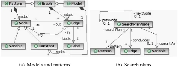
In the paper, we use a common, tool independent graph-based framework for representing in-stance models and graph patterns of rules in a uniform way by using an edge-labelled directed graph. In case of a pattern P, a node is either a constant (denoted by white boxes in gures) or a variable (marked by grey boxes in gures), while a model consists of constant nodes only. In-heritance can be handled in this representation by linking all types of a node (i.e., its direct class and all the supertypes) bytypeedges. A metamodel of our graph representation is presented in
Figure2(a).
A negative application condition [HHT96] is a graph morphism, which maps theLHSpattern
to aNAC pattern. A reduced NACpattern Q is such a subgraph of a NAC pattern that has (i)
the minimum number of nodes (called as shared nodes), and (ii) no edges in common with the correspondingLHSpattern P. A precondition pattern consists of the LHSpattern, the reduced NACpattern, and the mapping between them. In the paper, we only use reducedNACpatterns1
to ensure that the common edges of LHSandNACpatterns are tested only once during pattern
matching.
(a) Models and patterns (b) Search plans
Figure 2: Metamodel for models, patterns and search plans
Example. Figure4(c)presents a graph representation of an instance model. Both the classes of the metamodel (such as Package, Schema, etc.) and the objects of the instance model (such as p, s, etc.) uniformly appear as constant nodes. Instance-of relation between nodes is also represented by a dashed type edge. Other edge labels (like EO) are dened by the metamodel associations.
Figure1(b)presents the representation of the precondition of the GT ruleClassRule(depicted
in Figure1(a)). TheLHS pattern (shown by P32) has three variables for model-level elements
(s,p,c), three constants for metamodel-level elements (Schema, Package, Class), three type edges, one ref edge, and one EO edge. Similarly, the (reduced) NACpattern (shown by QB)
consists of variablesc, t, the constant Table, one ref edge and one type edge. Furthermore, variablecis a shared node, thus it is contained by both theLHSandNACpatterns.
2.2 Graph Pattern Matching and Search Plans
During graph pattern matching, each variable of a graph pattern is bound to a constant node in the model such that this matching (binding) is consistent with edge labels, and source and target nodes of the model. A matching for a precondition pattern is a matching for itsLHS pattern,
provided that no matchings should exist for itsNACpattern.
A search plan for a pattern prescribes an order of variables in which they are mapped during pattern matching. In the following, we suppose that a search plan already exists for each pattern, and vkwill denote the kth variable of a pattern according to the corresponding, xed search plan.
A (simplied) metamodel of search plans is depicted in Figure2(b).
The kth subpattern Pk is a subgraph of P where nodes consist of all constants and the rst k
variables (i.e., v1;:::;vk) of pattern P according to a corresponding search plan, and edges consist
of all edges of pattern P whose source and target nodes are both included in the selected set of nodes. Incoming (outgoing) condition edges of the kth subpattern Pk are the edges leading into
(out of) variable vk. Without loss of generality, in the following, we consistently use n to denote
the number of variables in a (complete) pattern Pn. Consequently, a pattern Pnwith n variables
has n+1 subpatterns (i.e., P0;:::;Pn). A partial matching for (complete) pattern Pnis a matching
for subpattern Pk. A maximal partial matching is a non-extensible partial matching, i.e., pattern
Pk+1cannot be matched.
Example. For instance, a matching of the LHS pattern P3of Figure1(b)in model Figure4(e)
is: c = c1, p = p, s = s. A matching of the NAC pattern (see QB in Figure 1(b)) in model
Figure4(g)is: c= c1,t= t1.
We dene a search plan for theLHS pattern by xing orders on variables (1)c, (2)p, (3)s. A search plan for theNACpattern is (A)t, (B)c.3 The position of a variable in a xed order is
denoted by a numbered circle in Figure1(b). Search plans are generated independently of each other in the current version of the pattern matching engine.
Based on these search plans, subpatterns ofLHSare shown by areas P0, P1, P2, P3surrounded
by solid (grey) borders in Figure1(b). Subpatterns ofNACare Q0, QA, QB, drawn by dashed (red)
borders. Note that P0and Q0denote the empty matchings for theLHSand theNAC, respectively.
2 The purpose of Pis and Qis will be explained later in Section2.2.
The EO edge connectingctopis an incoming condition edge of pattern P2, while the type
edge connecting p to Package represents an outgoing condition edge, since they are edges of pattern P2, and they lead into and out of the second variable (p) of the corresponding search plan
of theLHSpattern.
3 Data Structures for Incremental Pattern Matching
In this section, we present the data structures needed for the efcient storage of partial matchings. Class diagrams depicting the different aspects of data structures being used by the incremental pattern matching engine are shown in Figure3.
Matching and Matching Tree. A Matching (denoted by a numbered circle in Figure 4) represents a partial matching for a pattern. It contains a set of Bindings. Each binding denes a mapping of a Variable to a Constant.
For each pattern Pn, a matching tree is maintained, which consists of matchings being
orga-nized into a tree structure along parent-child edges (depicted by dashed arcs in Figure4). The root of the tree denotes the empty matching for the corresponding pattern, i.e., when none of the variables have been bound. Each level of the tree (denoted by light grey areas in Figure4) contains matchings for a subpattern of pattern Pn. The mapping of subpatterns to tree levels is
guided by the search plan having been xed for the pattern. A tree node in level k (i.e., hav-ing distance k from the root) represents a matchhav-ing of the kth subpattern behav-ing specied by the search plan. Each leaf represents a maximal partial matching for the pattern. By supposing that the pattern Pn has n variables, each leaf in (the deepest possible) level n represents a complete
matching of the pattern.
Example. Sample models of Figs.4(c), 4(e), and4(g)and the corresponding data structure contents are presented in Figs.4(d),4(f), and4(h), respectively. Figs.4(d),4(f), and 4(h)show matching trees in their top-right corner, they depict binding arrays at the bottom, while notica-tion arrays are presented in their left part.
Figure4(d)contains two matching trees representing the partial matchings of theLHSpattern
and theNACpattern, respectively. Matchings 1and2 denote empty matchings. Matching3 is
located on the rst tree level of theLHSpattern, thus, it is a matching for subpattern P1, which
contains a single binding that maps variablecto constant c1. Matching3is a child of matching 1, as the latter can be extended by the mapping of variablec.
(a) Matchings (b) Event processing (c) Pattern matcher
Schema Package Class Table
s p c t
type
type type type
ref EO ref
(a) Precondition pattern for ClassRule (b) Notational guide for data structures
Package Schema Class Table PKey UniqueKey Column Attribute Feature p c1 s
typetype type
type
ref ref
(c) Model 1 (d) Data structure contents for Model 1
Package Schema Class Table PKey UniqueKey Column Attribute Feature p c1 s typetype type
type
ref ref
EO
(e) Model 2 (f) Data structure contents for Model 2
Package Schema Class Table PKey UniqueKey Column Attribute Feature p c1 t1 s pk1 col1 type type type
type type type type type type type type ref ref ref ref
EO EO EO
CF UF
(g) Model 3 (h) Data structure contents for Model 3
In the context of Figure4(d), matching3is a maximal partial matching as it cannot be further
extended, due to the lack of outgoing EO edges leading out of c1. On the other hand, matching
3, is not a maximal partial matching in Figure4(f)as it can be extended e.g., by mappingspto p andsto s to get matching5. This means a complete matching for theLHSpattern as matching5
is located on the lowest tree level P3.
Binding Arrays. Matchings are physically stored as one-dimensional binding arrays, which are indexed by the variables. An entry in a binding array stores variableconstant pairs in the corresponding matching. When one matching is an ancestor of another one, their binding arrays can be shared in order to reduce memory consumption as the ancestor matching contains a subset of the bindings of the descendant matching. Consequently, for each pattern Pnwith n variables, a
binding array match[n] of size n is used. In gures, binding arrays are connected to matchings by solid black lines.
Example. Since the LHSpattern has 3 variables, matchings of theLHStree refer to binding
arrays having 3 entries as it is shown e.g., in the lower part of Figure4(f). Each column of the binding array of theLHSmatching tree represents a binding of variables (upper row) to constants
(lower row). Note that memory consumption can be reduced by sharing binding arrays among a matching and any of its ancestors in the matching tree. E.g., the array that contains mappings cto c1, pto p andsto s can be shared by matchings 1,3,4, and5, as they only consist of the
rst 0, 1, 2, and 3 bindings of the array, respectively. In spite of the fact that a completely lled binding array is assigned to matching3in Figure4(f), this matching only makes use of the single mappingcto c1 in the algorithms.
Invalidation Edges. Invalidation edges, which are denoted by thick (red) arcs, represent the invalidation of partial matchings of aLHScaused by complete matchings of aNAC.
Example. The red invalidation edge of Figure 4(h)connecting matchings7 to3means that
matching7is a complete matching for theNACpattern, which invalidates matching3as both map
the shared variablecto the same constant c1. As long as matching3is invalidated (as shown by the incoming invalidation edge), it cannot be part of a complete matching for theLHSpattern,
which fact is marked by the empty subtree rooted at matching3.
Notication Arrays. Since the transformation engine sends notications on model changes, notication related data structures (shown in Figure 3(b)) are also needed. The incremental pattern matching engine has a single INSERT and a single DELETE notication array consisting of notication entries.
An entry in the delete notication array is a pair consisting of a DeleteKey and a list of Matchings to be notied. If an edge e with label e.lab connecting e.src to e.trg is removed from the model, then Matchings of such delete notication array entry is notied whose DeleteKey is of the form [e.src,e.lab,e.trg].
Example. Sample notication arrays are presented e.g., in the left part of Figure 4(d). The INSERT notication array has 4 entries of which the rst is triggered by the InsertKey [*,type,Class] and refers to matching 1. This entry means that matching 1 has to be
notied, when a type edge leading to Class is inserted into the model. Similarly, the rst en-try in the DELETE notication array means that matching3must be notied, if the type edge
connecting c1 to Class is deleted.
Query Index Structure. A query index structure (not shown in gures) is also dened for each precondition pattern to speed-up the queries of complete matchings initiated by the GT tool that use the services of the incremental pattern matching approach.
4 Incremental Operations on an Example
During the incremental operation phase, the matching tree is maintained by four main methods of class Matching.
1. The insert() method is responsible for the possible extension of the current partial matching for proper subpattern Pkto create a new partial matching for subpattern Pk+1.
2. The validate() method is responsible for the recursive extension of insert operations to all (larger) subpatterns.
3. The delete() method removes the whole matching subtree rooted at the current match-ing for subpattern Pk.
4. The invalidate() method is responsible for the recursive deletion of all children matchings of the current matching.
These methods are called by the pattern matching engine when edge modication events arrive from the model repository.
Insert edge notication. If an edge e with label e.lab connecting constants e.src to e.trg is added to the model, then the insert() method of class Matching is invoked (i) with parameter e.trg on every matching as dened by entry INSERT[e.src, e.lab,*], and (ii) with parameter e.src on every matching as dened by the entry INSERT[*,e.lab,e.trg].
Due to space restrictions, we only exemplify the process by using our running example of Figure4. (The details of the algorithms can be found in [VVS].) Let us suppose that a class c1 is added to package p in the model by user interaction initiated by the system designer. The pattern matching engine is notied about this activity in two steps. First a notication arrives about the insertion of a type edge connectingc1to Class (see Figure4(c)) followed by the insertion of an EO edge connecting c1 to p (see Figure4(e)). Modications are denoted by thick lines.
Step 1. At the insertion of a type edge connectingc1to Class, the pattern matching engine looks up entries retrieved by insert keys [c1,type,*] and [*,type,Class].
The latter entry triggers the possible extension of the empty matching1by mapping variable
cto constant c1 by invoking the insert() method on matching1with parameter c1. As this
binding is a matching for pattern P1, (i) a new matching3is created and added to the (matching)
tree as a child of matching1, and (ii) the bindingcto c1 is recorded.
Then matching 3 is inserted into the delete notication array with delete key [c1,type,
Class]. This means that whenever the type edge from c1 to Class (i.e., the edge that has been just added) is removed, this matching should be deleted.
Effects of adding a new matching to the tree are recursively extended to nd matchings for larger subpatterns by calling validate. Matching 3 can be further extended (as shown by
corresponding new entries being added to the insert notication array pointing to matching3),
whenever an edge with label EO leading out of c1 or with label type leading to Package is added to the model in the future.
As also the current content of the model may extend matching 3, we initiate the possible
extensions of this matching by checking the existence of at least the EO edges leading out of c1.4
As no such edges exist in our example, the algorithm terminates with the matching tree presented in Figure4(d).
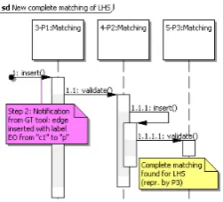
Step 2. When EO edge connecting c1 to p is inserted (as shown by the thick line of Figure4(e)), matching3 is rst extended to a new matching 4 by mapping variablep to constant p and by executing a sequence of insert() and validate() method calls as shown in Figure5.
Figure 5: Sequence diagram showing edge insertion into theLHSpattern
4 Note that the insert key generation and the possible further extension of matching 3 are guided by the condition
This time, matching extension is propagated to another new matching 5 by assignings to s by invoking the insert method on matching4with parameter s, as the current model already
contained ref and type edges connecting p to s and s to Schema, respectively.
In addition, both new matchings are appropriately registered in both the insert and delete notication arrays, and the binding array is updated accordingly. The corresponding matching tree is shown in Figure4(f).
At this point, matching5represents a complete matching for theLHSpattern, so the GT rule
ClassRulecan be applied.
Step 3. The result of applying the GT ruleClassRule on matching5 can be observed in
Fig-ure 4(g) after the insertion of some 13 edges, processed one by one by the pattern matching engine.
Let us suppose that the new ref edge between c1 and t1 is processed rst, which is followed by the insertion of of type edge connecting t1 to Table. The rst edge causes no modications in data structures as no appropriate insert keys appear in the insert notication array.
At the second edge insertion, matching 2 is notied by invoking its insert method with
parameter t1, which creates matchings6and7. As the latter is a complete matching of theNAC
pattern QB, matching3must be invalidated by deleting all its descendant matchings in the tree.
When all the 13 edges are added, the data structure will reect the situation in Figure4(h).
5 Experimental Evaluation
In order to assess the performance of our incremental approach, we performed measurements on the object-relational mapping benchmark example [VFV06]. As a reference for the measure-ments, we selected Fujaba [FNTZ98] as it is among the fastest non-incremental GT tools.
By using the terminology of [VSV05], graph transformation rules, the initial model and the transformation sequence have to be xed up to numerical parameters in order to fully specify a test set.
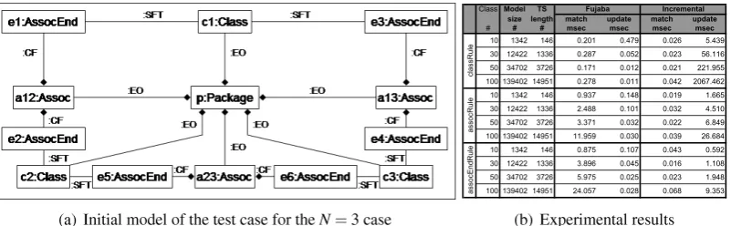
(a) Initial model of the test case for the N = 3 case
Class Model TS
size length match update match update
# # # msec msec msec msec
10 1342 146 0.201 0.479 0.026 5.439 30 12422 1336 0.287 0.052 0.023 56.116 50 34702 3726 0.171 0.012 0.021 221.955 100 139402 14951 0.278 0.011 0.042 2067.462 10 1342 146 0.937 0.148 0.019 1.665 30 12422 1336 2.488 0.101 0.032 4.510 50 34702 3726 3.371 0.032 0.022 6.849 100 139402 14951 11.959 0.030 0.039 26.684 10 1342 146 0.875 0.107 0.043 0.592 30 12422 1336 3.896 0.045 0.016 1.108 50 34702 3726 5.975 0.025 0.023 1.948 100 139402 14951 24.057 0.028 0.068 9.353
Incremental Fujaba asso cR ul e cl assR ul e as so cE ndRule
(b) Experimental results
Figure 6: Initial model and measurement results
Associationand 2AssociationEndsare added to the model for each pair ofClasses, thus initially,
we have N(N 1)=2Associationsand N(N 1)AssociationEnds. Associationsare also contained
by the singlePackageas expressed by the corresponding links of typeEO. EachAssociationEndis
connected to a correspondingAssociationandClassby aCFandSFTlink, respectively.
The object-relational mapping can be specied by 4 graph transformation rules, which de-scribe how to generate the relational database equivalents ofPackages,Associations,Classes, and
AssociationEnds, respectively. (Due to space restrictions, the exact benchmark specication is
omitted from the paper. The reader is referred to [VFV06].) The transformation sequence con-sists of the application of these rules on each UML entity in the order specied above.
Measurements were performed on a 1500 MHz Pentium machine with 768 MB RAM. A Linux kernel of version 2.6.7 served as an underlying operating system. The time results are shown in Figure6(b).
The head of a row shows the name of the rule on which the average is calculated. (Note that a rule is executed several times in a run.) The second column (Class) depicts the number of classes in the run, which is, in turn, the runtime parameter N for the test case. The third and fourth columns show the concrete values for the model size (meaning the number of model nodes and edges) and the transformation sequence length, respectively. Heads of the remaining columns unambiguously identify the approach having been used. Values in matchandupdate
columns depict the average times needed for a single execution of a rule in the pattern matching and updating phase, respectively. Execution times were measured on a microsecond scale, but a millisecond scale is used in Figure6(b)for presentation purposes.
Our experiments can be summarized as follows.
In accordance with our assumptions, the incremental engine executes pattern matching in constant time even in case of large models, while the traditional engine shows signicant increase when theLHSof the pattern is large as in case ofassocEndRule.
Incremental techniques by their nature suffer time increase in the updating phase due to (i) the bookkeeping overhead caused by the additional data structures, and (ii) the fact that even the insertion of a single edge may generate (or delete) a signicant amount of match-ings. Its detrimental performance effects are reported in the updating phase ofclassRule,
when also the matchings of the other rules have to be refreshed. On the other hand, the traditional engine executes the update phase in constant time as it can be expected.
By taking into account both phases in the analysis, it may be stated that the incremental strategy provides a competitive alternative for traditional engines as the total execution times of the incremental approach are of the same order of magnitude in case of the fre-quently applied rules (i.e.,assocRuleandassocEndRule).
The benets of the incremental approach are the most remarkable (i) when rules have complexLHSgraphs as the pattern matching of Fujaba gets slow in this case and (ii) when the dependency between rules is weak as this leads to fast updates in incremental engines.
matchings of a rule have to be accessed rapidly, which is a typical case for analysis/verication tools.
6 Related Work
Incremental updating techniques have been widely used in different elds of computer science. Now we give a brief overview on incremental techniques that could be used for graph transfor-mation.
Rete networks. [BGT91] proposed an incremental graph pattern matching technique based on the idea of Rete networks [For82], which stems from rule-based expert systems. In their approach, a network of nodes is built at compile time from theLHSgraph to support incremental
operation. Each node performs simple tests on the entities (i.e., nodes, edges, partial matchings) arriving to its input(s). If the test succeeds, the node groups entities into compound ones, which are then put into its output. On the top level of the network, there are nodes with a single input that let such objects and links of a given type to pass that have just been inserted to or removed from the model. On intermediate levels, network nodes with two inputs appear, each representing a subpattern of theLHSgraph. These nodes try to build matchings for the subpattern from the
smaller matchings located at the inputs of the node. On the lowest level, the network has terminal nodes, which do not have outputs. They represent the entireLHSpattern. Entities reaching the terminals represent complete matchings for theLHS.
The technique of [BGT91] shows the closest correspondance to our approach, as matching levels can be considered as nodes in the Rete network. However, it is not a one-to-one mapping as one matching level in our approach corresponds to several Rete nodes. As a consequence, Rete-based solutions have more bookkeeping overhead as they store information at the inputs of nodes in local memories and they use more nodes.
Two signicant consequences can be drawn from this similarity. (i) All techniques (e.g., the handling of common parts of differentLHSpatterns at the same network node [MB00]) that have
already been invented for Rete-based solutions are also applicable to our approach. (ii) The idea of notication arrays can speed-up traditional Rete-based approaches used in a graph transfor-mation context as these arrays help identifying those partial matchings that may participate in the extension of the matching. Thus, it is subject to our future investigations.
PROGRES. The PROGRES [SWZ99] graph transformation tool supports an incremental technique called attribute updates [Hud87]. At compile-time, an evaluation order of pattern variables is xed by a dependency graph. At run-time, a bit vector having a width that is equal to the number of pattern variables, is maintained for each model node expressing if a variable can be mapped to a given node.
When model nodes are deleted, some validity bits are set to false according to the dependency graph denoting the termination of possible partial matchings. In this sense, PROGRES (just like our approach) performs immediate invalidation of partial matchings. On the other hand, validation of partial matchings are only computed on request (i.e., when a matching for the LHS is requested), which is a disadvantage of the incremental attribute updating algorithm.
View updates. In relational databases, materialized views, which explicitly store their content on the disk, can be updated by incremental techniques. Counting and DRed algorithms [GMS93] rst calculate the delta (i.e., the modications) for the view by using the initial contents of the view and base tables and the deltas of base tables. Then the calculated deltas are performed on the view.
In contrast to our approach, view updating algorithms are more exible as they use a run-time evaluation order for delta calculation, and they can provide both lazy and eager style updates being specied when a view is created.
[VFV06] proposed an approach for representing graph pattern matching in relational
data-bases in form of views. Although some initial research (reported in [VV04]) has been done for incremental pattern matching in relational databases, this solution has been completely thrown away as it suffers from the inadequate support of incremental algorithms by the underlying databases and the strong restrictions being posed on the structures of the select query that denes the view.
7 Conclusion
In the current paper, we proposed data structures for incremental graph pattern matching where all matchings (and non-extensible partial matchings) of a rule are stored explicitly in a matching tree. This matching tree is updated incrementally triggered by the modications of the instance graph. Negative application conditions are handled uniformly by storing all matchings of the corresponding patterns. As the main added value of the paper, we introduced a notication mechanism by maintaining additional registries for quickly identifying those partial matchings, which are candidates for extension or removal, and thus, which have to be notied when an edge is inserted to or deleted from the model.
Limitations. We have also identied certain limitations of the presented algorithms. First of all, the efciency of the incremental pattern matching engine highly depends on the selection of search plans as even a single edge insertion (or deletion), which affect matchings located at upper levels of the tree (i.e., near to its root) may trigger computation intensive operations. As a consequence, further investigations on creating good search plans for the incremental pattern matching engine have to be carried out.
Our current solution provides a suboptimal solution, when patterns contain a large number of loop edges. This is related to the fact that our approach currently stores only the matchings of the nodes but not the edges (i.e., edges do not have identiers), which assumption can be relaxed in the future.
At rst glance, it can be strange that NACs are handled independently of the LHS (i.e., all matchings of the NAC are calculated). The goal of our approach is to support the reusability of patterns when the same pattern can be used once in the LHS and once as a NAC, or the same NAC is a negative condition for multiple LHSs (as in VIATRA2 [BV06]).
implementation of the pattern merger and optimizer module to be able to share matchings across matching trees, and (v) the incremental handling of path expressions.
Acknowledgements: This work was partially carried out during the visit of the rst author to TU Darmstadt (Germany), and it was partially funded by the SegraVis RTN. The rst and the second author had partial support from the SENSORIA European IP (IST-3-016004). The second author was also partially supported by the J. Bolyai Scholarship.
Bibliography
[BGT91] H. Bunke, T. Glauser, T.-H. Tran. An Efcient Implementation of Graph Grammar Based on the RETE-Matching Algorithm. In Proc. Graph Grammars and Their Ap-plication to Computer Science and Biology. LNCS 532, pp. 174189. 1991.
[BV06] A. Balogh, D. Varr´o. Advanced Model Transformation Language Constructs in the VIATRA2 Framework. In Proc. of the 21st ACM Symposium on Applied Computing. Pp. 12801287. ACM Press, Dijon, France, April 2006.
[D¨or95] H. D¨orr. Efcient Graph Rewriting and Its Implementation. LNCS 922. Springer-Verlag, 1995.
[EEKR99] H. Ehrig, G. Engels, H.-J. Kreowski, G. Rozenberg (eds.). Handbook on Graph Grammars and Computing by Graph Transformation, volume 2: Applications, Lan-guages and Tools. World Scientic, 1999.
[ERT99] C. Ermel, M. Rudolf, G. Taentzer. In [EEKR99]. Chapter The AGG-Approach: Lan-guage and Tool Environment, pp. 551603. World Scientic, 1999.
[FNTZ98] T. Fischer, J. Niere, L. Torunski, A. Z¨undorf. Story Diagrams: A new Graph Rewrite Language based on the Unied Modeling Language. In Engels and Rozenberg (eds.), Proc. of the 6th International Workshop on Theory and Application of Graph Trans-formation. LNCS 1764, pp. 296309. Springer Verlag, 1998.
[For82] C. L. Forgy. RETE: A fast algorithm for the many pattern/many object match prob-lem. Articial Intelligence 19:1737, 1982.
[GMS93] A. Gupta, I. S. Mumick, V. S. Subrahmanian. Maintaining Views Incrementally. In ACM SIGMOD Proceedings. Pp. 157166. Washington, D.C., USA, 1993.
[HHT96] A. Habel, R. Heckel, G. Taentzer. Graph Grammars with Negative Application Con-ditions. Fundamenta Informaticae 26(3/4):287313, 1996.
[Hud87] S. E. Hudson. Incremental Attribute Evaluation: an Algorithm for Lazy Evaluation in Graphs. Technical report 87-20, University of Arizona, 1987.
[MB00] B. T. Messmer, H. Bunke. Efcient Subgraph Isomorphism Detection: A De-composition Approach. IEEE Transactions on Knowledge and Data Engineering 12(2):307323, 2000.
[PCTM02] J. Poole, D. Chang, D. Tolbert, D. Mellor. Common Warehouse Metamodel. John Wiley & Sons, Inc., 2002.
[SWZ99] A. Sch¨urr, A. J. Winter, A. Z¨undorf. In [EEKR99]. Chapter The PROGRES Ap-proach: Language and Environment, pp. 487550. World Scientic, 1999.
[VFV06] G. Varr´o, K. Friedl, D. Varr´o. Implementing a Graph Transformation Engine in Re-lational Databases. Software and Systems Modeling 5(3):313341, September 2006. [VSV05] G. Varr´o, A. Sch¨urr, D. Varr´o. Benchmarking for Graph Transformation. In Proc. of the 2005 IEEE Symposium on Visual Languages and Human-Centric Computing. Pp. 7988. IEEE Computer Society Press, Dallas, Texas, USA, September 2005. [VV04] G. Varr´o, D. Varr´o. Graph Transformation with Incremental Updates. In Heckel
(ed.), Proc. of the 4th Workshop on Graph Transformation and Visual Modeling Techniques (GT-VMT 2004). ENTCS 109, pp. 7183. Elsevier, Barcelona, Spain, December 2004.
[VVS] G. Varr´o, D. Varr´o, A. Sch¨urr. Incremental Graph Pattern Matching.http://www.cs.
bme.hu/gervarro/publication/IncrementalEngine.pdf.