Proceedings of the
Eighth International Workshop on
Graph Transformation and Visual Modeling Techniques
(GT-VMT 2009)
Improved Flexibility and Scalability by Interpreting Story Diagrams
Holger Giese, Stephan Hildebrandt and Andreas Seibel
12 pages
Guest Editors: Artur Boronat, Reiko Heckel
Managing Editors: Tiziana Margaria, Julia Padberg, Gabriele Taentzer
Improved Flexibility and Scalability by Interpreting Story Diagrams
Holger Giese1, Stephan Hildebrandt1and Andreas Seibel1
1[holger.giese|stephan.hildebrandt|andreas.seibel]@hpi.uni-potsdam.de
System Analysis and Modeling Group,
Hasso Plattner Institute for Software Systems Engineering, University of Potsdam, Germany
Abstract: In this paper, we present an interpreter for Story Diagrams working on
Eclipse Modeling Framework (EMF) models. The interpreter provides a more flex-ible and, under certain circumstances, a more scalable solution than the compiled Java code generated from Story Diagrams by Fujaba. of Dynamic EMF even al-lows the evolution of meta models at runtime. Story Diagrams can now be modeled and executed within Eclipse. They can be modified and re-executed by the Story Diagram interpreter immediately without recompiling the source code and restart-ing the application. Our implementation also supports higher-order transformations by using Story Diagrams to modify other Story Diagrams. generation is not appli-cable, like running systems. While interpretation obviously results in performance drawbacks, we demonstrate that the Story Diagram interpreter is able to improve the performance in certain worst-case situations compared to the average generated code. This is achieved by a dynamic ordering of the matching process, which con-siders the actual number of elements in an association at runtime. Such a dynamic ordering can minimize the matching effort considerably. In contrast, Fujaba gener-ated code uses a static matching strategy. Whereas the Fujaba Story Diagrams have potentially high performance fluctuations, the performance of the Story Diagram interpreter is steadier and more scalable compared to the generated Java code.
Keywords:Graph Transformation Systems, Interpreter, Story Diagram
1
Introduction
Story Diagrams [FNTZ00], as supported by the Fujaba Tool Suite1, are an established graph transformation approach. They have been employed in several applications ranging from be-havior specification [FNTZ00], reverse engineering [NSW+02], consistency checking [WGN03,
GMW06], and as an implementation technique for model transformations with Triple Graph
Grammars [GW09,GH08] (TGG).
In this paper, we present our new interpreter for Story Diagrams, which works directly on Eclipse Modeling Framework (EMF)2 models. It allows directly executing Story Diagrams to access and modify arbitrary EMF-based models. This leads to a higher flexibility. On the one hand, Story Diagrams are now available in Eclipse and EMF. This streamlines our workflows. Currently, EMF models are imported into Fujaba, Story Diagrams are modeled with Fujaba, code is generated, and the code is exported back to Eclipse. One the other hand, Story Diagrams can
1 http://www.fujaba.de
be modified and re-executed by the Story Diagram interpreter immediately without recompiling the source code and restarting the application. The additional steps of generating code, compiling code and integrating it into the runtime environment disappear. Modeling Story Diagrams within EMF leverages higher-order transformations [MCG05] because Story Diagrams can be used to modify other Story Diagrams.
Furthermore, the interpreter also supports Dynamic EMF. Dynamic EMF objects are not in-stantiated from specifically generated code classes but from a generic class. This allows creating and modifying meta models and their instances in runtime environments where the application of code generation is not feasible.
During the development of a model transformation system based on Triple Graph Grammars, we encountered performance issues when executing code generated from Story Diagrams by Fujaba. The reason is the static pattern matching strategy used by the generated code, which is occasionally not the optimal pattern matching strategy. The interpreter uses a dynamic pattern matching strategy, which first tries to find matches using those instance links with the lowest number of elements. This is also the optimal matching strategy in many cases and results in a better scalability compared to Java code with a non-optimal static matching strategy. We have conducted an evaluation that compares the runtime performance of the interpreter with the com-piled Java code of Fujaba. As outlined in [VSV05] and [TBB+08], Fujaba has been shown to be one of the most efficient graph transformation engines in comparison to AGG [T¨00], PROGRES
[REEK99], GReAT [BNBK06], and other approaches. Because of that observation, we restrict
our analysis to a direct comparison between the new Story Diagram interpreter and the compiled Java code of Fujaba.
The paper is structured as follows: We first describe Story Diagrams as supported by Fujaba in Section2. Then, we describe our EMF-based meta model of Story Diagrams and the Story Diagram interpreter in Section 3. In Section 4 we discuss the benefits of interpreting Story Diagrams implying a higher flexibility (Section 4.1) and scalability (Section 4.2). The paper closes with some final remarks and an outlook on planned future work in Section5.
2
Story Diagrams in Fujaba
Story Diagrams extend UML Activity Diagrams by so-called Story Activities to model the be-havior of a method of a UML Class. Therefore, they are usually used in conjunction with a UML Class Diagram that describes the structure of a software application. Fujaba is a UML CASE tool that supports Story Driven Modeling (SDM), which comprises the modeling of Story Diagrams and the generation of Java code from UML Class Diagrams and their accompanying Story Diagrams. This way, it is possible to completely create Java applications using the models provided by Fujaba. Besides Story Activities, Story Diagrams can also contain other kinds of activities like Statement Activities. These activities contain plain Java code. User defined code is inserted into the code which is generated by Fujaba. The user-defined code can access objects matched and created in previous Story Pattern executions and it can create objects that can be used in following Story Patterns. More details on Story Diagrams can be found in [FNTZ00].
Figure1shows a meta model that reflects a simplified UML Class Diagram and Figure2shows an example Story Diagram that describes thedoSomething()method of theStoryDiagramTester
class. It operates on instances of the meta model of Figure2.
Figure 1: Example meta model of a simplified UML Class Diagram
Figure 2: Example Story Diagram
that is executed on the object graph of a running application. Story Patterns can match existing objects, create new objects or delete objects of the running application. For example, the Story Pattern in Figure2searches for aUMLClassobject that is connected to theumlClassDiagramvia
theelementslink, and to aUMLStereotypeobject (stereotype) via astereotypeslink. The Story
Pattern objectumlClassDiagramis already bound to the object that was supplied as the method’s parameter. The other two Story Pattern objects are unbound. When the Story Pattern is executed, matches for these Story Pattern objects are searched for in the application’s object graph. If all Story Pattern objects can be bound to an instance object, a newUMLStereotypeobject is created (indicated by<<create>>) and connected to theumlClassand theumlClassDiagramobjects.
3
Story Diagram Interpreter Based on EMF
In this section, we will describe the developed Story Diagram interpreter and briefly describe the meta model of our Story Diagrams, which is based on EMF. The interpreter is implemented as a plug-in for the Eclipse framework.
Ecore Meta Meta Model
StoryDiagram Meta Model
Meta Model MM1
StoryDiagram
Model Model M1
«instance» «instance»
«instance» «instance»
«references»
StoryDiagram Interpreter
execute Story Diagram on
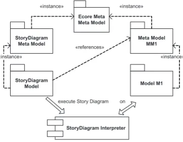
Figure 3: Models used by the Story Diagram interpreter.
in-stances of the Ecore meta meta model. This includes the meta model of Story Diagrams. Figure3
shows these relationships. Story Diagram models are in turn instances of the Story Diagram meta model. Another meta model (MM1 in Figure3) is required that defines the elements that can be matched and modified by a Story Diagram, e.g., classes, operations and associations. Especially, the definition of the operation is required, whose behavior is modeled by the Story Diagram. Therefore, a Story Diagram model references this meta model. Of course, it is also possible, that a Story Diagram references multiple meta models, including its own meta model.
To execute a Story Diagram, the interpreter needs that Story Diagram, as well as an instance of the meta model that is referenced by the Story Diagram (M1). These are supplied as parameters to the interpreter. During execution, that model may be modified, depending on the behavior modeled by the Story Diagram. If the operation defined in the meta model (MM1) also has parameters and a return value, these additional parameters can be supplied to the interpreter. The return value is returned when the interpretation is finished.
The use of the common meta meta model Ecore allows to access all EMF-based models in a uniform way. All instance objects provide a generic interface to access their properties and have a reference to their meta class, that provides information about the properties of that object. This allows working on any EMF-based models without knowing their meta models at design time. Dynamic EMF objects push that concept even further. Usually, code is generated by EMF and objects at runtime are instances of these generated classes. Dynamic EMF objects are not instantiated from specifically generated code classes but from a generic class. Their attributes and associations can only be accessed via the generic interface mentioned above. The Story Diagram interpreter uses only this generic interface to access and modify objects and, therefore, can execute Story Diagrams defined on any EMF-based meta model and can handle normal and dynamic EMF objects.
3.1 Story Diagram Meta Model
Before explaining the interpreter in more detail, we will look at the meta model of Story Dia-grams. While Fujaba’s meta model of Story Diagrams is intended to be used to generate code, it is unsuitable for interpreting a Story Diagram. This is mainly due to the fact, that statement activities contain plain Java code but Java code cannot be executed directly by our interpreter. We also support OCL for constraints, which also require changes to the Meta model. Further-more, Fujaba uses a proprietary meta meta model that makes integration with other tools difficult. Therefore, we built a new Story Diagram meta model based on EMF.
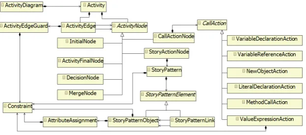
This meta model is shown in Figure4. The root node of a diagram,ActivityDiagram, contains severalActivities, each models a method’s behavior. EachActivitycontains severalActivityNodes
that are connected byActivityEdges. These edges can have guards to conditionally branch the control flow. There are several types of ActivityNodes to model the entry and exit points of the method, branches, Story Patterns and imperative calls. This follows the notion of Activity Diagrams of UML 2.0.
InitialNodes, ActivityFinalNodes, DecisionNodesandMergeNodesdescribe the control flow
inside anActivity.CallActionNodescan be used for imperative calls,StoryActionNodesdescribe Story Patterns.
AStoryPatterncontainsStoryPatternObjectsthat are connected byStoryPatternLinks.
repre-Figure 4: EMF-based Story Diagram meta model
sent instance links of associations. StoryPatternObjectscan be augmented by Constraintsand
AttributeAssignments.Constraintsdefine conditions that must be met in order to match that
Sto-ryPatternObjectto an instance object. AttributeAssignmentsassign a new value to an attribute.
They are only executed after a valid match for the wholeStoryPatterncould be found. The val-ues ofAttributeAssignmentsare calculated byConstraints. TheStoryPatternitself can also have
aConstraint that is checked when matches for allStoryPatternElementscould be found. This
is useful to specify constraints that include multipleStoryPatternObjects. Constraints on
Sto-ryPatternObjectsmay not include other elements of the same StoryPatternbecause these other
elements might not be bound when the constraint is evaluated.
Constraints are uniformly handled byConstraintobjects. They contain the constraint expres-sion and the type of the constraint language. Currently, only OCL is supported. Constraints can either evaluate to a Boolean value or an object. The latter case is used forAttributeAssignments
to compute values.
CallActionNodestry to resemble Fujaba’s capability to use arbitrary Java code in statement
activities. There are several types of CallActions, that can create a new variable and assign a value to it, reference an existing variable, create a new object, define a literal of a primitive type, evaluate an OCL expression and, most importantly, call arbitrary Java methods via Java’s reflection mechanism (MethodCallAction). This way, user defined code can be integrated into the execution of the Story Diagram.
3.2 Story Diagram Interpreter
Our tool support for modeling Story Diagrams is currently limited to the tree-based editor gen-erated by EMF from the Story Diagram meta model. We are working on a graphical editor using GMF to ease modeling Story Diagrams. Furthermore, we provide a set of basic validation rules using openArchitectureWare’s3Check language.
The Story Diagram interpreter is also based on Eclipse. It consists of four major parts (cf. meta model in Figure5): TheStoryDiagramInterpreter, that manages the interpretation of an activity,
theStoryPatternMatcher, responsible for executing a single Story Pattern, the
CallActionNodeIn-terpreter, responsible for executing call action nodes, and theInterpreterVariablesManager, that
stores the variables used in the activity along with their instance values. It is also used to evaluate
Figure 5: Meta model of the Story Diagram interpreter
OCL constraints using an OCL interpreter.4
InterpreterVariablesare used to store information about the variables used in a Story Diagram
at runtime. They are created for used every variable. These are especiallyStoryPatternObjects
but also the parameters of the operation.
To start the interpretation of an activity, the method executeStoryActivity()of the
StoryDia-gramInterpreter is called. The parameters of the method are the activity to interpret, a list of
values that are used as parameters for the operation modeled by the activity, and thethisobject in whose context the activity will be executed.
The interpreter traverses the activity starting at theInitialNode. If aCallActionNodeor a
Sto-ryActionNodeis encountered, theCallActionIntepreteror theStoryPatternMatcherare called to
execute that node. In case ofDecisionNodes, constraints on outgoing activity edges are evaluated and the interpreter branches accordingly. If a final node is reached, the execution ends and the return value of the Story Diagram is returned to the caller.
Figure 6: Story Activity of the methoddoSomething()
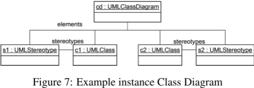
Figure 7: Example instance Class Diagram
The StoryPatternMatcher uses a dynamic pattern matching approach. It first tries to find
matches forStoryPatternObjectsusing those associations, which contain the lowest number of elements. Figure 6 shows an example Story Diagram and Figure7 an instance situation. All references are bidirectional. The instance objectcdis supplied as a parameter to the activity.
Starting fromumlClassDiagram, the first Story Pattern object has to be bound by iterating the
elementsassociation. Assume, the interpreter matchesstereotypetos1. Now,umlClasscan be
bound by either iteratingelements a second time, or by following thestereotypeslink froms1. Because the latter contains fewer elements, it is preferred. A possible match for the last Story Pattern objectstereotype2is searched for by following thestereotypeslink fromc1. But because the only elements1is already bound to another Story Pattern object, no match can be found. Therefore, the matches forumlClassandstereotypeare discarded and the interpreter tries to find another match forstereotype. But this attempt also fails in the example.
To perform this dynamic matching process, the Story Pattern is analyzed prior execution and
StoryPatternLinksare grouped into to-one and to-many links. When the interpretation starts, it is
checked if a to-one link exists, that starts at a boundStoryPatternObjectand ends at an unbound one. If such a link exists, it is used to bind the targetStoryPatternObjectof the link. Otherwise, the to-many links are searched. Now, the actual number of elements in the instance association is also checked and the link with the lowest number is followed to bind the nextStoryPatternObject. After aStoryPatternObjectwas bound, constraints on that object are evaluated and all links are checked, that now have a bound source and target. If these conditions are not met, the match is discarded and another is sought. If they are met, the next link to bind objects is looked up. When allStoryPatternObjectscould be bound, constraints on theStoryPatternare evaluated. If these are fulfilled,StoryPatternObjectsmarked as delete or create are deleted and created, and
AttributeAssignmentsare executed.
To keep track of matches, a stack is used. Every time, a Story Pattern object is bound, an element is put on the stack, that contains lists of all bound and unbound objects, and checked and unchecked to-one and to-many links. If no match can be found for a Story Pattern object, the top-most stack element is removed and the pattern matching continues using the state of the now top-most stack element. If the stack runs empty, no match could be found for the Story Pattern.
For debugging purposes, adapters can be registered at the interpreter. Each time, the interpreter performs an action, a notification is send to the adapters. This can be used to print messages to a log or to implement a graphical debugger for Story Diagrams.
The dynamic pattern matching strategy allows adapting the matching strategy to the instance situation. This is useful, if the optimal matching strategy for a Story Pattern differs depending on the instance situation. However, the interpreter’s matching strategy is not optimal in every case. Cases can be constructed, where traversing a link with many target elements first results in a lower overall execution time. But these cases are rather the exception than the rule.
4
Benefits of the Interpreter
In this section, we outline the benefits of the introduced Story Diagram interpreter. We discuss the improved flexibility in Section4.1and the steadier and improved scalability in Section4.2. On both aspects, we discuss the impact on projects we are currently working on.
4.1 Flexibility
• We can improve our workflow because we completely ported SDM to the EMF-based Eclipse platform. Thus, we are able to model and maintain Story Diagrams and further execute them within the same environment.
• We do not need to generate source code from Story Diagrams, which entails the compila-tion of Story Diagrams and further the integracompila-tion of the compiled code into the environ-ment for execution.
• We can use other EMF-based tools on Story Diagrams. For example, openArchitecture-Ware’s Check language is used to check well-formedness of Story Diagrams. EMF com-pare5could be applied to compare different versions of Story Diagrams etc.
• We have an explicitly defined meta model of Story Diagrams (Ecore) within Eclipse. This enables to integrate Story Diagrams in the definition of Story Diagrams, which is the prerequisite for higher-order transformations. Fujaba does not allow referencing the Story Diagram meta model within Story Diagrams.
• The support of Dynamic EMF enables to do transformations on meta models without generating code of the mega models. This is most desirable in runtime environments when code generation is not applicable.
Currently, we are working on two projects, where Story Diagrams are frequently used, which are briefly explained in the following. Both projects benefit from the first to facts in the previous listing.
The first project deals with traceability management in an Eclipse-based Model-Driven En-gineering (MDE) environment.6 We have developed a prototypical MDE environment, which is able to model the deployment of software products provided by a company into a model of an IT infrastructure reflecting a customer’s IT. Furthermore, the software products, which are modeled in the deployment models, are configured variants of reference models, which contain details of the software product necessary for the deployment domain. Between these models, we have several kinds of relationships tracing certain aspects, which are required to be managed and maintained. The management/maintenance operations for these traceability relationships are ex-pressed by means of Story Diagrams (create and delete operations). Thus, if specific situations in a certain model instantiation exist, there will be Story Diagrams in order to create new relation-ships between models/model elements and delete existing relationrelation-ships, which became invalid because of unsatisfied constraints expressed in Story Diagrams.
The first prototype suffered from an uncomfortable workflow we were forced to use. Story Diagrams had to be specified within the CASE tool Fujaba. This required re-modeling the meta models of the MDE models in Fujaba in order to specify the Story Diagrams. Further, code for each Story Diagram had to be generated, the code had to be complied and finally integrated into the Eclipse MDE environment. Furthermore, once the MDE environment is deployed to end-users, adding or updating existing Story Diagrams requires an additional mechanism to generate Story Diagram code, compile the code and integrate it into the running MDE environment.
In a subsequent implementation we encountered that the integration of SDM into Eclipse fixed all these issues. We can model Story Diagrams within the same environment, and instantly execute them after specification which safes a lot of time to the user of the environment. Thus, the whole SDM integration brings more flexibility to the user in this project.
In the other project, a model transformation and synchronization system based on Triple Graph Grammars [GH08] (TGG) was developed. The system is also based on Eclipse and EMF. The user specifies a set of declarative TGG rules that describe the model transformation. These rules are translated into Story Diagrams to make them operational. In this step, some operational logic is integrated into the Story Diagrams to support features like incremental transformation and synchronization of the models. Next, Java code is generated from the Story Diagrams. A transformation engine executed this code to perform model transformations.
The SDM integration could now improve the usability of the system because it would improve the workflow. After the TGG rules are created by the user and transformed to Story Diagrams, these could be executed instantly without the need to generate code and restart the transformation system. This saves a lot of time when a new set of transformation rules needs to be tested and debugged.
4.2 Scalability
During the development of the TGG-based model transformation system in Eclipse, we discov-ered that the static matching strategy of the generated code could have a severe impact on the performance of the overall transformation system. The Story Patterns in the Story Diagrams are quite complex and the code generator seldom chooses the optimal matching strategy. Especially in case of large models, this leads to bad scalability of the transformation system. We tried to avoid the problem by splitting complex Story Patterns into simpler ones toguidethe code gen-erator in choosing the best strategy. However, this does not work in all cases and it increases the complexity of the overall Story Diagrams making debugging and testing of the transformation system more difficult. Therefore, the dynamic matching strategy of the Story Diagram Inter-preter would improve the situation. We could use complex Story Patterns (and simpler Story Diagrams) and still be sure to have the best matching strategy in most cases.
To compare the dynamic matching strategy to the fixed matching strategies of compiled code generated by Fujaba, we have conducted a small benchmark7. Of course, this is not meant to be an exhaustive performance evaluation. It is only limited to the pattern matching parts. Other performance bottlenecks, like the OCL interpreter, are not considered.
For the benchmark, a simple Class Diagram model was created conforming to the meta model in Figure 1. In the test models, each UMLClassis connected to exactly one UMLStereotype
object and vice versa, i.e. the number of classes and stereotypes is the same. Figure7shows the general scheme. Test models of different sizes ranging from 200 to 100,000UMLClassobjects were created, which means a total number of 401 to 200,001 elements. On these test models, the Story Diagram shown in Figure6 was executed and the time was measured. The test was repeated ten times for each model size and the mean time was calculated. Because the Story Pattern cannot find a match in the instance models, the whole instance models must be traversed.
7 The benchmarks were run on a PC running on an Intel T5500 Core2 Duo Processor with 1.66 GHz and 2.5
We tested three versions of Java code generated by Fujaba from the Story Diagram, and the interpreter. The interpreter was tested one time using the implementation code generated from the Class Diagram meta model, the other time using only dynamic objects. This will show the performance penalty when dynamic objects are used.
The code generated by Fujaba uses a fixed matching strategy, which is defined at generation time. The code generator prefers to-one associations to match Story Pattern objects. Surprisingly, the matching order is also influenced by the order in which the links of the Story Pattern are created when the Story Diagram is modeled.
For the example Story Diagram, there are three major categories of matching strategies. The first strategy iterates a single time over the elements association to bind the first Story Pattern object (e.g. stereotype). The remaining two Story Pattern objects are bound via the stereotype
links. This order is depicted in Figure6by the numbers. It is the most efficient strategy for the instance models used in the benchmark and is also used by the Story Diagram interpreter. The second strategy iterates theelementslink two times, the third strategy iterates even three times. Because the iteration over theelementsassociation dominates the processing effort, the impact of the model size on the performance can be expected to be much higher than for the first strategy. For each of these categories, we generated code with Fujaba by varying the order in which the Story Pattern links were created.8
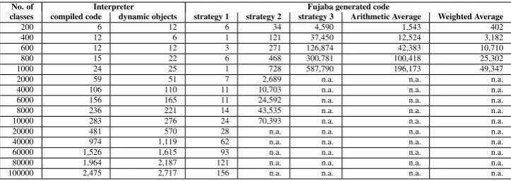
No. of Interpreter Fujaba generated code
classes compiled code dynamic objects strategy 1 strategy 2 strategy 3 Arithmetic Average Weighted Average
200 6 12 6 34 4,590 1,543 402
400 12 6 1 121 37,450 12,524 3,182
600 12 12 3 271 126,874 42,383 10,710
800 15 22 6 468 300,781 100,418 25,302
1000 24 25 1 728 587,790 196,173 49,347
2000 59 51 7 2,689 n.a. n.a. n.a.
4000 106 110 11 10,703 n.a. n.a. n.a.
6000 156 165 11 24,592 n.a. n.a. n.a.
8000 236 221 14 43,535 n.a. n.a. n.a.
10000 283 276 24 70,393 n.a. n.a. n.a.
20000 481 570 28 n.a. n.a. n.a. n.a.
40000 974 1,119 62 n.a. n.a. n.a. n.a.
60000 1,526 1,615 93 n.a. n.a. n.a. n.a.
80000 1,964 2,187 121 n.a. n.a. n.a. n.a.
100000 2,475 2,717 156 n.a. n.a. n.a. n.a.
Table 1: Average execution time of the interpreter and generated code in msec.
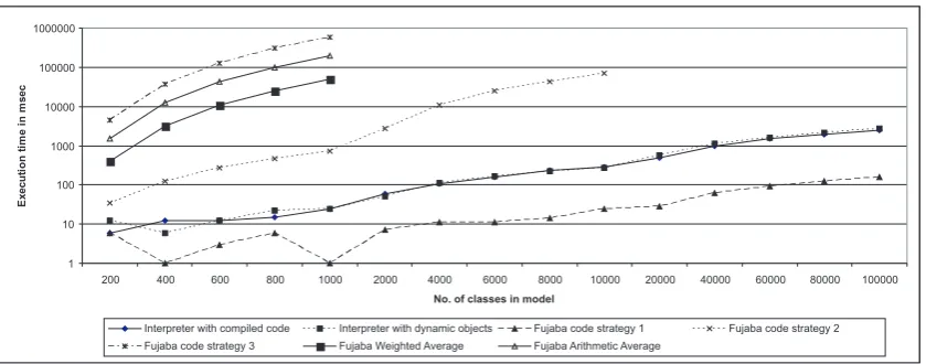
The results of the benchmarks are shown in Table1and Figure8. Note the logarithmic scale of the diagram. We also calculated the arithmetic and a weighted average9of the Fujaba generated code versions. The weighted average can be seen as the expected value for the execution time of the generated code if the links in the example Story Diagram are created in a random order.
As expected, the performance of the second and third strategies heavily depends on the number of elements in the model. The execution time grows exponentially. The interpreter is generally slower than the first Fujaba code version, but the execution time is still acceptable. The
perfor-8 An exception is the first strategy. For some reason, Fujaba only generated code that uses the second or third
strategies. Therefore, we had to ”force” the code generator by removing twoelementslinks from the Story Pattern and inserting the existence check for these links in the generated code manually. This is probably a bug in the code generator.
9 The weighted average is calculated by giving the first strategy a weight of 0.417, the second a weight of 0.5 and
1 10 100 1000 10000 100000 1000000
200 400 600 800 1000 2000 4000 6000 8000 10000 20000 40000 60000 80000 100000
No. of classes in model
E x e c u ti o n ti m e in m s e c
Interpreter with compiled code Interpreter with dynamic objects Fujaba code strategy 1 Fujaba code strategy 2 Fujaba code strategy 3 Fujaba Weighted Average Fujaba Arithmetic Average
Figure 8: Average execution time of the interpreter and generated code (logarithmic scale)
mance of the interpreter and the first Fujaba generated code strategy depend almost linearly on the model size.
The dynamic pattern matching guarantees a good, and in many cases also optimal, matching strategy. Therefore, the interpreter can make up the performance drawback if the generated code does not use an optimal pattern matching strategy. This is especially useful, if there is no generally optimal matching strategy for a given Story Pattern, but the optimal strategy varies depending on the instance objects. This will definitely be a benefit for the model transformation system mentioned above.
Surprisingly, the use of dynamic objects instead of compiled implementation code does not affect the performance very much. For models up to 10,000 classes the difference to using compiled implementation code for the model elements is not even significant. So the additional flexibility of dynamic objects does almost not come at the expense of performance.
5
Conclusion and Future Work
In this paper, we presented an interpreter for Story Diagrams based on EMF models and Eclipse. The whole SDM implementation improved the flexibility in our research projects because of an improved workflow, the lapse of generating Java code and applying the interpreter for executing Story Diagrams. It further enables the application of EMF-based tools for further validation purposes, as well as higher-order transformations.
Furthermore, the interpreter uses a dynamic matching strategy, which makes the performance of the interpreter scale more steadily. Although the interpreter is generally slower than compiled code, it can be faster in cases where the static matching strategy of compiled code is not optimal. In future work, a dynamic matching strategy may be incorporated into generated code to combine the advantages of both approaches.
Bibliography
[BNBK06] D. Balasubramanian, A. Narayanan, C. van Buskirk, G. Karsai. The Graph Rewriting and Transformation Language: GReAT.Electronic Communications of the EASST 1, 2006.
[FNTZ00] T. Fischer, J. Niere, L. Torunski, A. Z¨undorf. Story Diagrams: A New Graph Rewrite Lan-guage Based on the Unified Modeling LanLan-guage and Java. InTAGT’98: Selected papers from the 6th International Workshop on Theory and Application of Graph Transformations. Pp. 296–309. Springer-Verlag, London, UK, 2000.
[GH08] H. Giese, S. Hildebrandt. Incremental Model Synchronization for Multiple Updates. In Pro-ceedings of GraMoT”08, May 12, 2008, Leipzig, Germany. 2008.
[GMW06] H. Giese, M. Meyer, R. Wagner. A Prototype for Guideline Checking and Model Transfor-mation in Matlab/Simulink. InProc. of the 4th International Fujaba Days 2006, Bayreuth, Germany. Technical Report tr-ri-06-275, pp. 56–60. University of Paderborn, 2006.
[GW09] H. Giese, R. Wagner. From model transformation to incremental bidirectional model syn-chronization.Software and Systems Modeling, 1 2009.
[MCG05] T. Mens, K. Czarnecki, P. V. Gorp. 04101 Discussion – A Taxonomy of Model Trans-formations. In Bezivin and Heckel (eds.), Language Engineering for Model-Driven Soft-ware Development. Dagstuhl Seminar Proceedings 04101. Internationales Begegnungs- und Forschungszentrum fuer Informatik (IBFI), Schloss Dagstuhl, Germany, 2005.
[NSW+02] J. Niere, W. Sch¨afer, J. P. Wadsack, L. Wendehals, J. Welsh. Towards pattern-based design recovery. InICSE ’02: Proceedings of the 24th International Conference on Software Engi-neering. Pp. 338–348. ACM, New York, NY, USA, 2002.
[REEK99] G. Rozenberg, H. Ehrig, G. Engels, H.-J. Kreowski.HANDBOOK of GRAPH GRAMMARS and COMPUTING by GRAPH TRANSFORMATION Volume 2: Applications, Languages and Tools. World Scientific, 1999.
[T¨00] G. T¨antzer. AGG: A Tool Enviroment for Algebraic Graph Transformation. InProc. of Appli-cations of Graph Transformation with Industrial Relevance (AGTIVE2000), Kerkrade, The Netherlands. Lecture Notes in Computer Science (LNCS). Springer Verlag, 2000.
[TBB+08] G. Taentzer, E. Biermann, D. Bisztray, B. Bohnet, I. Boneva, A. Boronat, L. Geiger, R. Geiß, A. Horvath, O. Kniemeyer, T. Mens, B. Ness, D. Plump, T. Vajk. Generation of Sierpinski Triangles: A Case Study for Graph Transformation Tools. Pp. 514–539, 2008.
[VSV05] G. Varro, A. Schurr, D. Varro. Benchmarking for Graph Transformation. InVLHCC ’05: Pro-ceedings of the 2005 IEEE Symposium on Visual Languages and Human-Centric Computing. Pp. 79–88. IEEE Computer Society, Washington, DC, USA, 2005.