Self-Compacting Paste Systems using Secondary Raw Materials
S. A. Rizwan1 and T. A. Bier21
Civil Engineering Department, University of Engineering and Technology, Lahore, Pakistan (Presently National University of Science and Technology, Islamabad)
2 Technical University of Freiberg, Germany
Abstract
A study has been carried out on self-compacting paste (SCP) systems using various cements and secondary raw materials (SRM’s) including rice husk ash (RHA) and Silica Fume (SF). These systems were characterized by SRM particle size, powder water demand (WD) and setting times, flow, strength, microstructure and early volume stability. The results show that WD increased by adding SRM’s due to their smaller particle size, higher surface areas and internal porosity. Inclusion of SRM’s in SCP systems as cement replacements also increases strength of SCP systems due to filler, hydration and pozzolanic actions which translate into pore refinement. It is demonstrated that the resultant properties of self-compacting cementitious systems (SCCS) depend upon the nature of SRM used.
Keywords:
Self-compacting paste systems, water demand, setting times, secondary raw materials, flow, strength, shrinkage and microstructure.1. Introduction
Self-compacting Paste (SCP) systems are the vehicles for aggregates present in self-compacting mortar (SCM) systems and self-compacting concrete (SCC) systems. The properties of modern concretes like high-performance concrete (HPC) and SCC depend very significantly on the properties of SCP systems 1, 2, 3, 4, 5 . In modern concretes, paste component usually contains suitable secondary raw materials (SRM’s) which improve or modify the properties of resulting SCM and SCC systems. Study usually starts with the SRM particle characterization by laser technique, scanning electron microscopy (SEM) or vapor sorption. Once SRM surface morphology, internal porosity and particle texture are understood, it becomes easy to explain the water demand (WD), flow, strength, microstructure and early linear shrinkage of SCCS.
2. Research Significance
The technology of SCC is the most recent and innovative and has been termed as the “technology of the decade”. Paste is vehicle for the transport of aggregates during flow of SCCS and surprisingly there is not enough reported research on SCP systems using various SRM’s [6]. SCP systems are also very important for the durability and service-life of SCCS because a paste system containing SRM’s enhances durability by reducing the maximum pore diameter in
addition to bringing in so many other benefits. This work also describes the sequence of experiments, to be done on cement based materials, to the engineers in Pakistan, so that the results could be better explained.
3. Materials
These consisted of CEM I 42.5R, CEM II –B/S 32.5R (30 % blast-furnace slag) and CEM III/B 32.5 N NW/HS/NA (70 % blast-furnace slag) as per DIN 1164:1, 2 & 8. SRM’s consisted of amorphous rice-husk ash (RHA) imported from USA and as produced silica fume (SF) of Germany. Melflux 1641 and 2651 by BASF Germany, third generation poly-carboxylate ester (PCE) type powder super plasticizers (SP), have been used for producing flow target of 30±1 cm measured by Hagermann’s’ mini slump cone of 6x7x10 cm dimensions. 4x4x16 cm prisms were cast for flexural and compressive strength testing at various ages as per DIN 196 standard. BET surface areas were measured by Beckmann Coulter LS 230 Laser granulometer. Microstructure was studied by mercury intrusion porosimetry (MIP) and scanning electron microscope (SEM) technique using FEI XL 30 environmental scanning electron microscope with field emission gun (ESEM FEG) which was capable of giving spot chemical analysis EDAX (energy dispersive X-ray analysis).Table 1 gives the physical and chemical properties of powders used.
Table 1: Physical and Chemical Properties of Powders used in the Study
Parameters CEM 1 CEM 11 CEM 111 RHA* SF
Specific gravity Particle size (d50), m BET surface Areas, m2/g Chemical Analysis (% mass) Loss on ignition
Silicon Dioxide
Aluminum Oxide (wt.%) Ferric Oxide Calcium Oxide Magnesium Oxide Sulfur Trioxide Sodium Oxide Potassium Oxide 3.15 18.42 1.098 2.75 19.17 5.21 2.39 61.12 2.78 3.30 1.25 1.01 2.99 21.13 1.23 5.45 22.17 7.08 1.66 52.44 4.39 4.04 1.00 0.99 2.97 14.38 3.23 0.75 28.13 10.02 0.94 43.28 8.36 5.98 0.94 0.78 2.26 6.8 28.92 4-6 90.0+% <0.01 0.032 0.60 0.37 0.14 0.14 2.30 2.35 12.16 20.46 1.6 95% 0.2 0.05 0.25 0.4 - 0.1 1.2 * The chemical analysis of RHA was provided by the source in USA.
4. SRM Shapes
Figure 1 shows the SEM pictures of SF and RHA which have been used as SRM’s. The details of these SRM’s can be found elsewhere [6].
Figure 1: (a) Silica Fume Particles, (b) Rice Husk Ash
Particle
5. Mixing and Curing Regimes
The mixing was done using Hobart Toni Technik mixer. The dry constituents of pastes along with powder type SP were manually mixed first and were then fed into the bowl of mixer containing the required mixing water. Slow mixing (145 rpm) was done for 30 seconds and then interior of the bowl was cleaned. Thereafter, the formulations received 150 seconds of fast mixing (285 rpm). The RHA formulations needed slightly more mixing time and looked very viscous due to irregular, abrasive and internally porous particles of RHA. Flow was measured and 4x4x16 cm prisms were cast for flexural and compressive testing at various ages. Linear shrinkage measurements were made. Curing for initial 24 hours was done in plastic containers wherein 90%+ relative humidity was maintained at 20°C as per DIN 196. Thereafter samples were marked, weighed and put in water at 20°C and were subsequently tested in saturated surface dry (SSD) condition.
6. Results
6.1 Water Demand
The WD of SCC consists of WD of powders and aggregates. WD of powders is about 95% of the WD of SCC formulation [6]. Therefore an approximate idea about the WD of SCC mix can be obtained even from the WD of the powders. Tables 2 and 3 give the WD and Vicat setting- times of various SCP systems incorporating SRM’s.
6.2 Flow
The flow was measured by using Hagermann’s mini-slump cone of 6x7x10 cm dimensions. The target
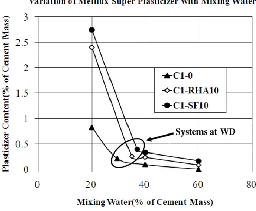
average flow spread diameter of 30 ± 1 cm was obtained by using varying amounts of SP for different formulations. It is a common perception amongst scientists and engineers that super-plasticizer (SP) gets grafted only on cement phases which is not true as some of the SP is adsorbed/entrapped by the SRM’s also [7].The rate and quantity of adsorbed SP depends upon the SRM particle characteristics including size, surface area,
internal porosity and morphology. Figure 2 shows the measurement of flow of SCP systems. It has been mentioned in the literature [6] that total flow spread is a function of yield of the formulation while the T25 cm spread provides an idea of the viscosity of the system as it measures the velocity and has been proposed by the author [6]. Figure 3 shows the SP demand of various SCP systems for obtaining the target flow.
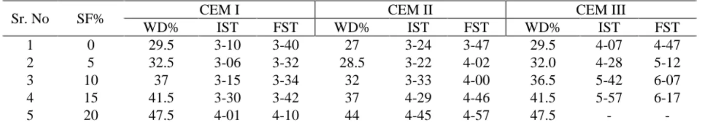
Table 2: Water Demands and Setting Times of Cement Pastes with SF
Sr. No SF% CEM I CEM II CEM III
WD% IST FST WD% IST FST WD% IST FST
1 0 29.5 3-10 3-40 27 3-24 3-47 29.5 4-07 4-47
2 5 32.5 3-06 3-32 28.5 3-22 4-02 32.0 4-28 5-12
3 10 37 3-15 3-34 32 3-33 4-00 36.5 5-42 6-07
4 15 41.5 3-30 3-42 37 4-29 4-46 41.5 5-57 6-17
5 20 47.5 4-01 4-10 44 4-45 4-57 47.5 - -
WD is per cent of cement mass. IST and FST stand for initial setting time and final setting times given in hours and minutes.
Figure 2: (a) Mini-Cone Flow Apparatus, (b) Flow Spread After Removal of Cone
Table 3: Water Demands of Cement Paste Systems with RHA
Water Demand %
CEM I with RHA% CEM II with RHA% CEM III with RHA%
0 5 10 0 5 10 0 5 10
29.5 32.5 35 27 28.5 31 29.5 33 36
Note: For 5% RHA IST= 4-14, FST= 5-04, with 10% RHA, IST= 6-17 & FST= More than 7 hours for CEM I
6.3 Strength
Strengths of the paste systems were determined as per EN 196-1: 1994 at the age of 1, 3, 7 and 28 days. The flexural strength at any age was the average of three specimens while compressive strength was the average
of six specimens. In total 252 prisms were cast for paste systems with CEM I and CEM III in laboratory at a temperature of 20 2 C and relative humidity of 35 5% as per EN 196-1:1994. It is shown that addition of mineral admixtures in SCP having mixing water more than the system’s demand increases the strength.
Figure 3: SP Demand of SCP Systems at Various Mixing Water Contents
Figure 4: (a) Age-Strength Relationship of SCP System at 40% Mixing Water with CEM I, (b) Age-Strength
Relationship of SCP System at 40% Mixing Water with CEM III.
6.4 Microstructure
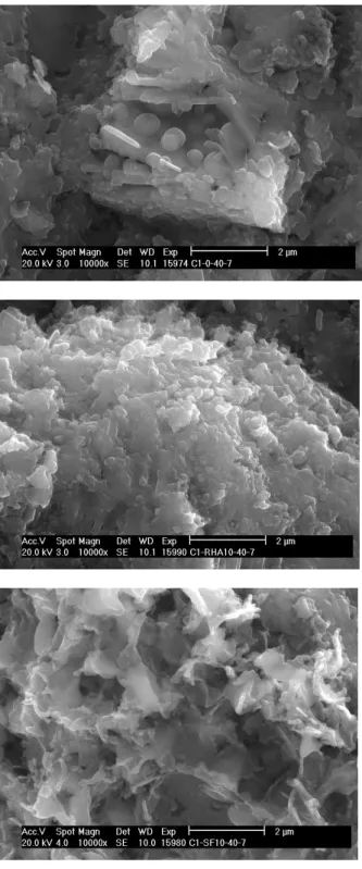
It was studied by SEM technique and MIP. Figure 5 shows SEM presentation of pure cement paste and those containing RHA and SF at 10% replacement level with 40% mixing water(w/c = 0.4) at the age of seven days. MIP was done with the help of Autoscan
33 Porosimeter. The contact angle was taken as 140 . Specimens were oven dried at 110 C for 24 hours. Figure 6 shows the maximum pore sizes (taken from partial MIP curves) and w/c ratio relation for the SCP systems studied. A typical formulation, for example, C I- SF10-40-7 means that it is a formulation with CEM 1 wherein SF equal to 10% of cement mass with 40%
mixing water has been used and the age of sample is 7 days.
6.5 Early Shrinkage
In this study a modified version of German classical “Schwindrinne” meaning shrinkage channel apparatus
Figure 5: (a) C1-0-40-7, (b) C1-RHA10-40-7 and
(c) C1-SF10-40-7
Figure 6: Maximum Pore Size and w/c Relation of
Pastes with and without SRM’s
measuring 4x6x25.4 cm was used at 20 1 C and RH of 31 5% with specimen uncovered and covered, the two possible exposure conditions for actual placements. It was interfaced with computer and had a sensitivity of 1.2microns/m. Paste samples with SRM’s were tested and measurements lasted for 24 hours. The average of two measurements is reported. The detailed treatment can be seen elsewhere [8-11].
Figure 7: (a) Early shrinkage of pastes with and
without SRM’s with CEM I, (b) early shrinkage of pastes with and without SRM’s with CEM III.
7. Discussion
The particle size of SF as measured by Laser technique (Table 1) is not that of a single particle but instead it is the size of electrically inter-connected particles forming primary group due to inter-particle cohesion. Therefore the particle size of SF can best be seen in SEM technique (Figure 1a) wherein it is clearly a sub-micron sized particle. Both SF and RHA have high internal porosity [9]. Figure 3 shows that for mixing water contents less than WD of the system, the SP content required for the desired flow (30±1 cm spread) is very high which further increases by inclusion of both RHA and SF because of the water uptake by these SRM’s. SP content required for the target flow for mixing water greater than the WD of the systems (40% & 60%), there is no substantial decrease in SP content when compared to that at WD itself. It establishes that for HPC/SCC, the formulations should contain mixing water equal to WD of the system for the reasons of economy and durability. Neat cement paste gave lesser strength due to their higher maximum pore sizes (Figure 5) than with those having SRM’s. With reference to Figure 4(a), RHA gave higher strength than SF in replacement mode with CEM III, than with CEM I, which may translate into saying that reaction products and processes of RHA in CEM III produce discontinuous porosity and these powders are more compatible. Both RHA and SF give almost equal 28 days strength at equal replacement level of 10%.Their incorporation improves the strength of neat self-compacting cement paste. This is due to their pore refinement effect(due to filler and pozzolanic actions) which can be seen in terms of maximum MIP pore radius, of paste systems at equal flow level, shown in Figure 6 at three water contents at the age of seven days. Figure 5(a) shows calcium hydroxide (CH) crystals in neat SCP which is due to the absence of a pozzolanic SRM/reaction. Figures 5(b &c) show the microstructure of SCP containing RHA and SF. The products of hydration are different which means the mechanisms of hydration of these binary binder systems are also different. Both figures show different crystal shapes, sizes and morphology but CH is not seen which means that pozzolanic reaction of a significant degree is present. However at different sites and at different w/c ratios, the nature and morphology of reaction products of SCP systems containing SF and RHA can show some resemblance also. The strength graphs should also be considered along with MIP results. Both compliment each other. The early volume stability in terms of linear adiabatic shrinkage measured in laboratory under controlled temperature and humidity shows that addition of RHA and SF in cement paste in a replacement mode increases the shrinkage, if kept uncovered, which is again attributed
to the water uptake by the internally porous particles of these SRM’s. However by covering the cementitious formulations immediately after placements, the shrinkage gets reduced due to thermal gradient and creation of expansive species. The modern curing techniques also suggest covering the placements in order to preserve the added water. Similar SCP formulations show higher early shrinkage with CEM III due to finer pores, lesser heat of hydration (lesser thermal expansion) and generation of lesser content of Ca(OH)2 crystals which are expansive in nature. A higher shrinkage does not necessarily mean wider shrinkage cracks or something like that. Covering a cement based formulation produces three times shrinkage reduction.
8. Conclusions
RHA can be readily locally available in Pakistan and seems to give a response similar to SF in cement based formulations. Based on this study it can be said that the SRM particle shape, size and morphology (particle characterization) is very important for modern cement based systems and those affect almost all the resulting properties. Modern concretes and cement based systems must have mixing water content close to the water demand of such systems for the reasons of economy and efficiency. There should be sufficient flow of formulations without bleeding and segregation. Both RHA and SF give almost similar improvements in the cement based formulations in terms of strength and microstructure. Similar formulations in CEM III gave higher early shrinkages than those in CEM I. The rate of strength development with CEM III is lower but beyond 28 days of age there is no significant difference in strength compared with those in CEM I. CEM III formulations are generally considered better in terms of microstructure and are considered more durable especially for water retaining and training structures and where excessive heat of hydration is undesirable.
Acknowledgements
The authors are thankful to Mr. Karl Kiser, Plant Manager, Agrilectric International Technologies, Lake Charles, LA USA for providing the RHA used in this investigation. We are grateful to Mr. Javed Bashir Malik, Associate/Structural group leader, Carter &Burgess, Houston Texas, USA for bearing the expenses of the RHA transportation to Germany.
REFERENCES
[1] ACI 209R-92(Re-approved 1997), Prediction of
concrete structures, American Concrete Institute, USA. [2] Almudaiheem, J.A. and Hansen, W.; Title no.
86-M35, ACI Materials Journal, (July-August 1989) 401-408.
[3] Ferraris, C. F. and Gaidis, J. M.; Title no 89-M43,
ACI Materials Journal, (July-August 1992) 388-39 [4] Guo, C. J.; Title No 91-M2, ACI Material
Journal, (January-February 1994) 13-25.
[5] Uno, P. J.; Title No 95-M34, ACI Materials Journal, (July-August 1998) 365-375.
[6] Rizwan, S. A.; PHD thesis, High Performance Mortars and Concretes Using Secondary Raw Materials, Technical University Bergakademie Freiberg, Germany, October 2006.
[7] Rizwan, S. A., Dombrowski, K., Bier, T. A. and Dahlhaus, F.; Proc. of 5th International RILEM
symposium (PRO 54), Ghent, Belgium, 1(2007), 509-514.
[8] Rizwan, S. A and Bier, T. A.; Proc. of eighth International Symposium on Brittle Matrix Composites (BMC-8), Warsaw, Poland, (2006), 175-186.
[9] Rizwan, S. A. and Bier, T. A.; Proc. of International RIELM conference on Volume Changes of Hardening Concrete: Testing and Mitigation, Technical University of Denmark, Lyngby, Denmark, (2006), 283-292.
[10]Rizwan, S. A. and Bier, T. A.; Proc. of 2nd all Russian International Conference on Concrete and reinforced Concrete - Development trends, Moscow, Russia, 3(2005), 727-732.
[11]Rizwan, S. A. and Bier, T. A., Proc. of 2nd International Conference on Concrete and Development, Tehran, Iran, (2005), 1-12.