User's Manual for
BeeHive204AP
Extremely fast universal 4x 48-pindrive concurrent multiprogramming system – core for automated programmer
BeeProg2AP
Extremely fast universal 48-pindrive programmer– core for automated programmer
ELNEC s.r.o. Presov, Slovakia 2nd September 2011
This document is copyrighted by ELNEC s.r.o., Presov, Slovakia. All rights reserved. This document or any part of it may not be copied, reproduced or translated in any form or in any way without the prior written permission of ELNEC s.r.o.
The control program is copyright ELNEC s.r.o., Presov, Slovakia. The control program or any part of it may not be analyzed, disassembled or modified in any form, on any medium, for any purpose.
Information provided in this manual is intended to be accurate at the moment of release, but we continuously improve all our products. Please consult manual on www.elnec.com. ELNEC s.r.o. assumes no responsibility for misuse of this manual.
ELNEC s.r.o. reserves the right to make changes or improvements to the product described in this manual at any time without notice. This manual contains names of companies, software products, etc., which may be trademarks of their respective owners. ELNEC s.r.o. respects those trademarks.
COPYRIGHT © 1991 - 2011 ELNEC s.r.o.
How to use this manual
This manual explains how to install the control program and how to use your programmer. It is assumed that the user has some experience with PCs and installation of software. Once you have installed the control program we recommend you consult the context sensitive HELP within the control program rather than the printed User's Manual. Revisions are implemented in the context sensitive help before the printed User’s Manual.
Dear customer,
thank you for purchasing one of the ELNEC programmer.
_____________________________________ Please, download actual version of manual from ELNEC WEB site (www.elnec.com), if
Table of contents
How to use this manual...3
Introduction...6
Products configuration ...7
PC requirements ...8
Free additional services: ...8
BeeHive204AP ...10
Introduction ...11
BeeHive204AP elements ...13
Selftest and calibration check ...14
Technical specification...16
BeeProg2AP...17
Introduction ...18
BeeProg2AP elements...19
Selftest and calibration check ...20
Multiprogramming by BeeProg2AP...22 Technical specification...22 Setup...23 Software setup ...24 Hardware setup...29 Pg4uw ...41
Pg4uw-the programmer software...42
File ...45 Buffer ...51 Device ...58 Programmer ...84 Options...87 Help...97 Pg4uwMC ...100 Common notes ...110 Maintenance ...111 Software ...112 Hardware ...118
ISP (In-System Programming) ...118
Other ...121
Troubleshooting and warranty...122
Troubleshooting ...123
If you have an unsupported target device...124
Conventions used in the manual
References to the control program functions are in bold, e.g. Load, File, Device, etc. References to control keys are written in brackets <>, e.g. <F1>.
Terminology used in the manual:
Device any kind of programmable integrated circuits or programmable devices ZIF socket Zero Insertion Force socket used for insertion of target device
PMI Programmer Module Interface - connectors used for insertion programming module to programmer
Buffer part of memory or disk, used for temporary data storage
Printer port type of PC port (parallel), which is primarily dedicated for printer connection.
USB port type of PC port (serial), which is dedicated for connecting portable and peripheral devices.
HEX data format format of data file, which may be read with standard text viewers; e.g. byte 5AH is stored as characters '5' and 'A', which mean bytes 35H and 41H. One line of this HEX file (one record) contains start address and data bytes. All records are secured with checksum.
This user's manual covers these ELNEC programmers: BeeHive204AP and BeeProg2AP. BeeHive204AP is the core for automated programmers and automatic test equipments (ATE). It is extremely fast universal 4x 48-pindrive concurrent multiprogramming system designed for high volume production programming. BeeHive204AP is an industrial version of BeeHive204. The chips are programmed at near theoretical maximum programming speed. Using build-in ISP connectors the programmer is able to program ISP capable chips in-circuit. BeeProg2AP is the core for automated programmers and automatic test equipments (ATE) too. It is a extremely fast universal programmer with 48 powerful pindrivers designed for low volume production programming. BeeProg2AP is an industrial version of BeeProg2. Using build-in ISP connector the programmer is able to program ISP capable chips in-circuit. Advanced design, including protection circuits, original brand components and careful manufacturing allows us to provide a three-years warranty for BeeHive204AP and BeeProg2AP on parts and labor for the programmers (limited to 500 insertion of programming module to Programming Module Interface connectors). This warranty terms are valid for customers, who purchase a programmer directly from Elnec company. The warranty conditions of Elnec sellers may differ depending on the target country law system or Elnec seller’s warranty policy.
Products configuration
program mer USB cable external powe r supplyAP1 PMI selftest pod AP1 ISP connector
selftest pod
AP1 calibration test
pod
ISP cable software
User’s manual registration card shipping case
BeeHive204AP • • • 1x 1x 1x 4x • • • •
BeeProg2AP • • • • • - • • • • •
Before installing and using your programmer, please carefully check that your package includes all next mentioned parts. If you find any discrepancy with respective parts list and/or if any of these items are damaged, please contact your distributor immediately.
PC requirements
Minimal PC requirements
OS Windo ws CP U RAM [M B ] fr ee disk spa ce [M B] USB 2.0 hig h speed USB 1. 1 CD ROM 2x BeeHive204AP XP C2D 2,6GHz 1000 400 • - • BeeHive204AP 2000 P4 512 200 • - • BeeProg2AP 2000 P4 256 200 - • •Recommended PC requirements
OS Windo ws CP U RAM [M B ] fr ee disk spa ce [M B] USB 2.0 hig h speed CDROM 2x BeeHive204AP XP – 7 C2Quad 2000 2000 • • BeeHive204AP XP – 7 C2D 1000 1000 • • BeeProg2AP XP – 7 C2D 1000 1000 • •These PC requirements are valid for 2.77/03.2011 version of control program for programmers. For other version see www.elnec.com.
Free disk space requirement depends also on used IC device size and number of attached programming sites. For large devices the required free space on disk will be approximately 1000MB + 2x Device size x number of programming sites attached to this PC.
Very easy indication, if your PC in hardware/software configuration is good enough for the current software version and current situation with Pg4uw/Pg4uwMC, is to run Windows task manager (Ctrl+Alt+Del) and see the performance folder. It have to be max. 80% of CPU usage at full run of programming system.
Free additional services:
Why is it important to use the latest version of the control
program?
• Semiconductor manufacturers continuously introduce new devices with new package types, manufactured by new technologies in order to support the need for flexibility, quality and
speed in product design and manufacturing. To keep pace and to keep you up-to-date, we usually implement more than 7000 new devices into the control program within a year.
• Furthermore, a typical programmable device undergoes several changes during its lifetime in an effort to maintain or to improve its technical characteristics and process yields. These changes often impact with the programming algorithms, which need to be upgraded (the programming algorithm is a set of instructions that tells the programmer how to program data into a particular target device). Using the newest algorithms in the programming process is the key to obtaining high quality results. In many cases, while the older algorithm will still program the device, they may not provide the level of data retention that would be possible with an optimal algorithm. Failure to not use the most current algorithm can decrease your programming yields (more improper programmed target devices), and may often increase programming times, or even affect the long term reliability of the programmed device.
• We are making mistakes too...
Our commitment is to implement support for these new or modified parts before or as soon as possible after their release, so that you can be sure that you are using latest and/or optimal programming algorithms that were created for this new device.
• free technical support (phone/fax/e-mail).
• free lifetime software update via Web site.
Free software updates are available from our Internet address www.elnec.com.
We also offer the following new services in our customer support program: Keep-Current and AlgOR.
• Keep-Current is a service by which ELNEC ships to you the latest version of the control program for programmer and the updated user documentation. A Keep-Current service is your hassle-free guarantee that you always have access to the latest software and documentation, at minimal cost. For more information see www.elnec.com.
• AlgOR (Algorithm On Request) service allows you to receive from ELNEC software support for programming devices not yet available in the current device list. For more information see www.elnec.com.
Introduction
BeeHive204AP is the core for automated programmers and automatic test equipments (ATE). It is extremely fast universal 4x 48-pindrive concurrent multiprogramming system designed for high volume production programming.
BeeHive204AP consist from four BeeProg2 based independent programming modules. The chips are programmed at near theoretical maximum programming speed.
BeeHive204AP is an industrial version of BeeHive204 programmer for usage in automated programmers. The differences are:
the dimensions of the BeeHive204AP programmer are reduced - compared to the BeeHive204 - in intent to minimize overhead of the handler's arm movement
more mechanically stable case to be immune against vibration during operation. The case
of BeeHive204AP is prepared to be fastened from top or from bottom of programmer
body into automated programmer working place
different construction of programming modules, stable enough for insert/replace chips by mechanical arm and also that allow to keep identical position of ZIF socket also after replacing of the module
Two BeeHive204AP units can be attached to one control PC to better utilize programming workplace. Elnec offer Windows XP Embedded driven BeeHive204AP control unit, which is able serve two BeeHive204AP programmers.
BeeHive204AP can be implemented into automated programmer (as a replacement of obsolete programmer) or into some handler by two ways:
1. using of standard PC, for example BeeHive204AP can be connected to the control PC of automated programmer (up to 2 BeeHive204AP can be attached to one computer using USB hub or USB ports of the PC).
2. using BeeHive204AP control unit (option)
Up to 2 BeeHive204AP programmers are controlled by BeeHive204AP control unit.
The BeeHive204AP control unit is Windows XP Embedded driven computer,
optimized for industrial environment.
One BeeHive204AP control unit in the system serve as a master unit. Here is running also multiprogramming control software, serialization engine and interface to the host system.
Interfacing of BeeHive204AP control units is done over standard LAN and external LAN switch. Interfacing of BeeHive204AP master control unit and host systems is over LAN or RS232 (other interface on request).
Implementation of BeeHive204AP into available 3rd party automated programmers and handlers is using simple remote control of the Pg4uwMC control software. There exist examples of implementation for standard programming languages and of course we are ready to help customer with this task.
Note: For other (standard) parameters of BeeHive204AP programmer, see description of
BeeHive204 please.
BeeHive204AP programming modules have schematics identical like modules for BeeHive204 programmer, but these modules are mechanically designed for perfect stability
at the top of the programmer and also in intent to keep identical position if the programming module is exchanged. There are available programming module for device in PLCC, SOIC, PSOP, SSOP, TSOP, TSSOP, TQFP, QFN (MLF), BGA and other packages.
Note: The programming modules have reference pin (corner) points to Left-Up corner of
programming module. We accept also orders for other orientation of ZIF socket at programming module if needed, discuss please situation with our sales department.
BeeHive204AP programmer is driven by comfortable and easy to use control program, which work with all versions of MS Windows from Windows XP to Windows 7 64-bit
It is important to remember that in most cases new devices require only a software update due to the BeeHive204AP is truly universal programmer. With our unique quick reaction to customer's needs - software update can be ready within a day from request by OnDemand software
Advanced design including protection circuits, original brand components and careful manufacturing and burning allows us to provide a three-year warranty on parts and labor for the BeeHive204AP (limited to 500 insertion of programming module to Programming Module Interface connectors).
BeeHive204AP elements
1) Programmer Module Interface (PMI) connectors 2) work result LEDs
3) power/sleep LED of site 4) ISP connector
5) Ø 4,5mm holes for fastening BeeHive204AP to bottom plate 6) M4 nuts for fastening BeeHive204AP to upper plate 7) programming module fixating screws
8) right site power supply connector
9) right site type B USB connector for PC ↔ BeeHive204AP communication cable 10) right site tie mount for fixating USB cable
11) rear site power supply connector
12) rear site type B USB connector for PC ↔ BeeHive204AP communication cable 13) rear site tie mount for fixating USB cable
14) temperature controlled fans
15) "GND" screw can be used for grounding of the programmer
Rear view to BeeHive204AP
Selftest and calibration check
If you feel that your programmer does not react according to your expectation, please run the programmer (ISP connector) selftest using AP1 PMI selftest pod (AP1 ISP connector selftest pod), enclosed with the standard delivery package.
Selftest of programmer
• Insert AP1 PMI selftest pod into Programmer Module Interface (PMI) connectors of the programmer.
• Run selftest of programmer in Pg4uw (Programmer / Selftest plus).
Selftest of ISP connector
• Insert AP1 ISP connector selftest pod into Programmer Module Interface (PMI) connectors of the programmer.
• Interconnect 20 pins connector of AP1 ISP connector selftest pod with an ISP connector of the programmer with an ISP cable, included in delivery programmer package. Be sure that pins are interconnected properly (i.e. 1-1, 2-2... 20-20).
• Run selftest of ISP connector in Pg4uw (Programmer / Selftest ISP connector…).
AP1 ISP connector selftest pod
Calibration test
• Insert AP1 calibration test pod into Programmer Module Interface (PMI) connectors of the programmer.
• Run calibration test of programmer in Pg4uw (Programmer / Calibration test).
Technical specification
GENERAL
• external power supply unit: operating voltage 100-240V AC rated, 90-264 VAC max., 47-63 Hz
• power consumption max. 60W active
• dimensions 310x205x61 mm (12.2x8.1x2.4 inch)
• weight (programmer) 3.5kg (7.7 lb)
• operating temperature 5°C ÷ 40°C (41°F ÷ 104°F)
Introduction
BeeProg2AP is the core for automated programmers and automatic test equipments (ATE). It is a extremely fast universal programmer with 48 powerful pindrivers designed for low volume production programming. Using build-in ISP connector the programmer is able to program ISP capable chips in-circuit.
BeeProg2AP is an industrial version of BeeProg2 programmer for usage in automated programmers. The differences are:
the dimensions of the BeeProg2AP programmer are reduced - compared to the BeeProg2 - It is important mainly for implementation into ATE machines
more mechanically stable case to be immune against vibration during operation. The case of BeeProg2AP is prepared to be fastened from top or from bottom of programmer body into automated programmer working place. For ISP programming only the case of BeeProg2AP can be fastened from left side too.
different construction of programming modules, stable enough for insert/replace chips by mechanical arm and also that allow to keep identical position of ZIF socket also after replacing of the module
BeeProg2AP can be implemented into automated programmer or ATE machine as ISP programmer identically as BeeProg2 programmer - using of standard PC. BeeProg2AP can be connected to the control PC of automated programmer too. Up to 8 BeeProg2AP can be attached to one computer using USB hub or USB ports of the PC
Implementation of BeeProg2AP into available 3rd party automated programmers and handlers is using simple remote control of the Pg4uwMC control software. There exist examples of implementation for standard programming languages and of course we are ready to help customer with this task.
Note: For other (standard) parameters of BeeProg2AP programmer, see description of
BeeProg2 please.
BeeProg2AP programming modules have schematics identical like modules for BeeProg2 programmer, but these modules are mechanically designed for perfect stability at the top of the programmer and also in intent to keep identical position if the programming module is exchanged. There are available programming module for device in PLCC, SOIC, PSOP, SSOP, TSOP, TSSOP, TQFP, QFN (MLF), BGA and other packages.
Note: The programming modules have reference pin (corner) points to Left-Up corner of programming module. We accept also orders for other orientation of ZIF socket at programming module if needed, discuss please situation with our sales department.
BeeProg2AP programmer is driven by comfortable and easy to use control program, which work with all versions of MS Windows from Windows XP to Windows 7 64-bit
It is important to remember that in most cases new devices require only a software update due to the BeeProg2AP is truly universal programmer. With our unique quick reaction to customer's needs - software update can be ready within a day from request by OnDemand software
Advanced design including protection circuits, original brand components and careful manufacturing and burning allows us to provide a three-year warranty on parts and labor for the BeeProg2AP (limited to 500 insertion of programming module to Programming Module Interface connectors).
BeeProg2AP elements
1) Programmer Module Interface (PMI) connectors 2) work result LEDs
3) power/sleep LED of site 4) ISP connector
5) M4 nuts for fastening BeeHive204AP to upper plate 6) programming module fixating screws
7) power supply connector
8) type B USB connector for PC ↔ BeeHive204AP communication cable 9) tie mount for fixating USB cable
10) temperature controlled fan
11) "GND" screw can be used for grounding of the programmer
Rear view to BeeHive204AP
Selftest and calibration check
If you feel that your programmer does not react according to your expectation, please run the programmer (ISP connector) selftest using AP1 PMI selftest pod (AP1 ISP connector selftest pod), enclosed with the standard delivery package.
Selftest of programmer
• Insert AP1 PMI selftest pod into Programmer Module Interface (PMI) connectors of the programmer.
• Run selftest of programmer in Pg4uw (Programmer / Selftest plus).
Selftest of ISP connector
• Insert AP1 ISP connector selftest pod into Programmer Module Interface (PMI) connectors of the programmer.
• Interconnect 20 pins connector of AP1 ISP connector selftest pod with an ISP connector of the programmer with an ISP cable, included in delivery programmer package. Be sure that pins are interconnected properly (i.e. 1-1, 2-2... 20-20).
• Run selftest of ISP connector in Pg4uw (Programmer / Selftest ISP connector…).
AP1 ISP connector selftest pod
Calibration test
• Insert AP1 calibration test pod into Programmer Module Interface (PMI) connectors of the programmer.
• Run calibration test of programmer in Pg4uw (Programmer / Calibration test).
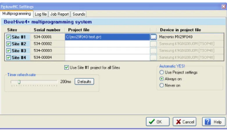
Multiprogramming by BeeProg2AP
During installation of Pg4uw at Select Additional Tasks window you check, if is allowed install BeeProg2AP multiprogramming control support.
For start of BeeProg2AP multiprogramming is necessary run special control program Pg4uwMC.exe. At this program user assign BeeProg2AP to control programs, may load projects for all BeeProg2AP and run Pg4uw for every connected and assigned BeeProg2AP.
Technical specification
GENERAL
• external power supply unit: operating voltage 100-240V AC rated, 90-264 VAC max., 47-63 Hz
• power consumption max. 20W active, about 2W sleep
• dimensions 84x205x61 mm (3.3x8.1x2.4 inch)
• weight 0.7kg (1.5 lb)
• operating temperature 5°C ÷ 40°C (41°F ÷ 104°F)
The programmer package contains a CD with the control program, useful utilities and additional information. The permission to freely copy the content of the CD is granted in order to demonstrate how ELNEC programmers work.
For programmers connected through USB port, control program requires correctly installed USB driver
We recommended install software before connecting programmer to PC to avoid unwanted complication during installation.
Software setup
Insert delivered CD to your CD drive and install program starts automatically (if not, run setup.exe). Install program will guide you through the installation process and will do all the necessary steps before you can first run the control program.
Step 1.
Click on “Install software for programmers” button. Step 2.
Step 3.
Click on “Next” button Step 4.
For default setting click on “Next” button. Setup will be continue with Step 6. For change default setting click on “Custom” and then on “Next” button.
Step 5.
For change default folder click on “Browse” button, select the destination folder. Then click on “Next” button
Step 6.
Step 7.
Check if “Install Multiprogramming control support” is selected. Change default setting, if you want. Then click on “Next” button Step 8.
Step 9.
Installation process will start. Step 10.
Step 11.
For Windows Vista only:
Click “This program installed correctly”
New versions of programmer software
In order to exploit all the capabilities of programmer we recommend using the latest version of Pg4uw. You may download the latest version of programmer software (file Pg4uwARC.exe) from our Internet site www.elnec.com.
Copy Pg4uwARC.exe to a temporary directory, disconnect programmer from PC and then launch it. Setup will start with Step 2 from previous chapter.
Hardware setup
When the programmer is connected to USB port before control program was installed, Windows will detect new hardware and ask user to select driver installation method: automatically or manually. To detect programmer correctly, control program installation CD must be inserted to computer's CD-ROM drive and following steps have to be done:
Step 1.
Directly connect USB cable to type B USB port on programmer. Step 2.
Directly connect USB cable to type A USB2.0 port on PC. Step 3.
Connect connectors of power supply cable to appropriate connectors on programmer and wall plug.
Step 4.
Programmer turn on. At this time all 'work result' LEDs light up successive and then LEDs switch off.
Step 5.
Windows will start with “Found new hardware wizard”. For Windows XP, Service Pack 2 users only:
Select “No, not this time” and then click on “Next” button. For all:
Step 6.
Wizard start searching programmer and start install driver automatically. Step 7.
After successfully installing of programmer you will see following window:
Click “Finish” button to finish setup. Step 8.
“Found new hardware wizard” will launch for each programmer (programmer site) one time (for BeeHive204AP 4 times). Hardware setup will be continued with Step 5.
Note: If a different USB port on the PC is used for the next connection of programmer, “Found new hardware wizard” will launch again and install new USB drivers.
Installation to target system
This chapter contains mechanical drawing of BeeHive204AP and BeeProg2AP and other information needed for installation BeeHive204AP and BeeProg2AP to target system.
BeeHive204AP
On picture bellow are overall dimensions of BeeHive204AP with programming modules. Total height of programmer with installed programming modules depends of programming module ZIF socket height. Total height can be determined by 68,5mm + ZIF socket height.
Right top view to BeeHive204AP with dimensions
At X axis a center of ZIF is same with center of programming module, but at Y axis not. For a lot of ZIFs, they center will be at the same position as on picture, but for some extra big ZIFs center of ZIF will be moved at Y axis.
If USB connector and power cable are connected to rear connectors, total depth of programmer will be 205mm + length of B type USB connector on USB cable. Total depth of programmer may be 205mm + 50mm.
If USB connector and power cable are connected to right side connectors, total width of programmer will be 310mm + length of B type USB connector on USB cable. Total depth of programmer may be 310mm + 50mm.
Mounting USB cable to case and length of USB connector with cable bending. For proper connection DC adapter to programmer, arrow on cable connector must be oriented to arrow on programmer connector.
Arrows on power supply connectors
This connector has locking mechanism, to avoid unwanted disconnection. For disconnecting is needed pull locking collar on cable connector.
BeeHive204AP can be mounted on base plate by 6 screws M4 with nuts. Length of screw depend on base plate thickness. On base plate can be ø 4,5mm holes replaced with M4 internal threads.
BeeHive204AP can be mounted bellow base plate by 6 screws M4. Length of screw depend on base plate thickness.
Attention: For proper mounting of programmer bellow base plate, mounting screws must be minimal 3mm depth in programmer. To avoid damage of PCB in programmer mounting screws must be maximum 8mm depth in programmer.
BeeProg2AP
On picture bellow are overall dimensions of BeeProg2AP with programming module. Total height of programmer with installed programming modules depends of programming module ZIF socket height. Total height can be determined by 68,5mm + ZIF socket height.
Right top view to BeeProg2AP with dimensions
At X axis a center of ZIF is same with center of programming module, but at Y axis not. For a lot of ZIFs, they center will be at the same position as on picture, but for some extra big ZIFs center of ZIF will be moved at Y axis.
USB connector and power cable are connected to rear connectors, total depth of programmer will be 205mm + length of B type USB connector on USB cable. Total depth of programmer may be 205mm + 50mm.
Mounting USB cable to case and length of USB connector with cable bending. For proper connection DC adapter to programmer, arrow on cable connector must be oriented to arrow on programmer connector.
Arrows on power supply connectors
This connector has locking mechanism, to avoid unwanted disconnection. For disconnecting is needed pull locking collar on cable connector.
BeeProg2AP can be mounted on base plate by 2 screws M3. Length of screw depend on base plate thickness.
Attention: For proper mounting of programmer on base plate, mounting screws must be minimal 3mm depth in programmer. To avoid damage of PCB in programmer mounting screws must be maximum 8mm depth in programmer.
BeeProg2AP can be mounted bellow base plate by 4 screw M4. Length of screw depend on base plate thickness.
Attention: For proper mounting of programmer on base plate, mounting screws must be minimal 3mm depth in programmer. To avoid damage of PCB in programmer mounting screws must be maximum 8mm depth in programmer.
BeeProg2AP can be mounted with left side on base plate by 4 screws M3. Length of screw depend on base plate thickness.
Attention: Before mounting BeeProg2AP in this way, unscrew two screws M3 located on left side. Then replace them with new M3 screws with proper length. For proper mounting of programmer on base plate, mounting screws must be minimal 3mm depth in programmer. To avoid damage of PCB in programmer mounting screws must be maximum 8mm depth in programmer.
Drawing for mounting programmer with left side on base plate:
Pg4uw-the programmer software
Program Pg4uw.exe is common control program for all ELNEC programmers. We guarantee running of these programs under all of above mentioned operating systems without any problems. Also background operation under Windows is error-free.
Using the programmer software
The control program delivered by ELNEC, included on the CD in your package, is granted to be free from any viruses at the moment of delivery. To increase their safety our programs include a special algorithm for detecting possible virus infections.
Run the control program
In Windows environment: double click to icon Pg4uw.
After start, control program Pg4uw automatically scan all existing ports and search for the connected any ELNEC programmer. Program Pg4uw is common for all the ELNEC programmers, hence program try to find all supported programmers.
Notes: When Pg4uw is started, program is checked for its integrity. Than the program display a standard user menu and waits for your instructions.
If the control program cannot communicate with the programmer, an error message appears on the screen, including error code and description of possible reasons (disconnected programmer, bad connection, power supply failure, incompatible printer port...). Eliminate the error source and press any key. If error condition still exists, the program resumes its operation in the demo mode and access to the programmer is not possible. If you cannot find the cause of the error, follow the instructions in Troubleshooting section. In addition, the control program checks communication with programmer prior to any operation with the programmed device.
Description of the user screen
Windows program Pg4uw
Toolbars
Under main menu are placed toolbars with button shortcuts of frequently used menu commands. Toolbars are optional and can be turned off by menu command Options / View. Log window
Log window contains the flow-control progress information about almost every operation made in Pg4uw.
Operation can be:
• starting of Pg4uw
• programmer search
• file/project load/save
• device operations (device read, blank check, programming, ...)
• remote control application connection and disconnection
• and other
Content of Log window can be saved to file concurrently while information is written to Log window. This option can be set by menu Options / General options (and tab Log file in dialog General options).
Panel Addresses
Panel Addresses contains information about actual address ranges of currently selected device, loaded file and buffer start-end address settings. Some devices allow modifying default device and buffer address ranges by menu command Device / Device options / Operation options.
Panel Addresses also contains some advanced information about current status of Split, Serialization and buffer checksum. For more information about each of the options, please look at:
• Split - menu Device / Device options / Operation options
• Serialization - menu Device / Device options / Serialization
• Checksum - menu Buffer / Checksum at section Checksum displayed in main window Panel Programmer
Panel Programmer contains information about currently selected programmer. The information includes
• programmer type
• port via programmer is connected to computer
• programmer status, can be one of following
• Ready - programmer is connected, successfully found and ready to work
• Not found - programmer is not found
• Demo - when user selects option (button) Demo in dialog Find programmer
• YES! mode - some types of programmers allow to use special modes of starting next device operation in one of following ways -
• manually by control program dialog Repeat
• manually by button YES! placed directly on programmer
• automatically - programmer automatically detects device removing and insertion of new device
For more details please look at Programmer / Automatic YES!. Panel Device
It contains information about currently selected device. The information includes
• device name (type) and manufacturer
• device adapter needed to use with currently selected programmer
• reference to detailed Device info dialog, available also by menu Device / Device info
• reference to Advanced device options - this is available for some types of devices only Panel Statistics
It contains statistics information about currently selected device. The information includes
• number of successful, failure and total device operations
Statistics and count-down options are available by menu command Device / Device options / Statistics or by mouse right click on panel Statistics and select item Statistics from popup menu
Panel File
The panel is placed on the bottom of Pg4uw main window. Panel shows currently loaded file or project name, size and date.
List of hot keys
<F1> Help Calls Help
<F2> Save Save file
<F3> Load Load a file into the buffer
<F4> Edit Viewing/editing of buffer
<F5> Select/default Target-device selection from 10 last selected devices list
<Alt+F5> Select/manual Target-device selection by typing device/vendor name
<F6> Blank Blank check
<F7> Read Reads device's content into the buffer
<F8> Verify Compares contents of the target device with the buffer
<F9> Program Programs target device
<Alt+Q> Exit without save Terminates the Pg4uw
<Alt+X> Exit and save Terminates the Pg4uw and saving settings too
<Ctrl+F1> Displays additional information about current device
<Ctrl+F2> Erase Fill's the buffer with a given value
<Ctrl+Shift+F2> Fill's the buffer with random values.
File
Menu File is used for source files manipulation, settings and viewing directory, changes drives, changes start and finish address of buffer for loading and saving files by binary,
MOTOROLA, MOS Technology, Intel (extended) HEX, Tektronix, ASCII space, JEDEC,
and POF format. The menu commands for loading and saving projects are located in this
submenu too.
File / Load
Analyse file format and loads the data from specified file to the buffer. You can choose the format desired (binary, MOTOROLA, MOS Technology, Tektronix, Intel (extended) HEX, ASCII space, JEDEC and POF). The control program stores a last valid mask for file listing. You can save the mask into the config. file by command Options / Save options.
The reserved key <F3> will bring out this menu from any menu and any time. Note for special x16 formats:
Intel HEXx16 is Intel Hex file format with 16 bits data word for TMS320F devices. Motorola HEXx16 is Motorola file format with 16 bits data word for TMS320F devices. Checking the check box Automatic file format recognition tells program to detect file format automatically. When program can't detect file format from one of supported formats, the binary file format is assumed.
When the check box Automatic file format recognition is unchecked program allows user to manually select wished file format from list of available file formats on panel Selected file
format. Default set is from Options / General options in panel Load file format at tab File options.
Attention: Program doesn't know recognize files in ASCII Hex format automatically, it
recognizes them as binary. So download files in ASCII Hex format with disabled option for automatic file format recognition.
Panel Additional operation
Checking the check box Erase buffer before loading tells the program to erase all buffer data using entered Erase value. Buffer erase is performed immediately before reading file content to buffer and it is functional for binary and all HEX file formats. Using this one-shot setting disables current setting of Erase buffer before loading option in menu Options / General options at tab Hex file options.
If the checkbox Swap bytes is displayed, the user can activate function of swapping bytes within 16bit words (or 2-byte words) during reading of file. This feature is useful especially when loading files with Motorola representation of byte order in file (big endian). Standard load file is using little endian byte order.
Note: Big-endian and little-endian are terms that describe the order in which a sequence of bytes are stored in computer memory. Big-endian is an order in which the "big end" (most significant value in the sequence) is stored first (at the lowest storage address). Little-endian is an order in which the "little end" (least significant value in the sequence) is stored first. For example, in a big-endian computer, the two bytes required for the hexadecimal number 4F52 would be stored as 4F52H in storage address 1000H as: 4FH is stored at storage address 1000H, and 52H will be at address 1001H. In a little-endian system, it would be stored as 524FH (52H at address 1000H, and 4FH at address 1001H).
Number 4F52H is stored in memory:
Address Big endian system Little endian system
1000H 4FH 52H
1001H 52H 4FH
Panel Buffer offset for loading
Panel Buffer offset for loading contains one-shot offset setting for loading data from file to buffer. The setting is used to specify optional offset of loaded data to store to buffer. When Load file dialog window is opened, offset has always default setting None. It means, no offset is used to store read data in buffer.
Available offset options are:
None this setting means, no offset is applied for loading data from file to buffer.
Positive offset set of offset value, which is added to current address to store data to buffer.
This offset is available for all formats and is used in x8 format, if current buffer organization is x8, or in x16 format, if current buffer organization is x16.
Negative offset mode has two options:
Negative offset and Automatic negative offset - set by two ways: manual or automatic. For manual set use option Negative offset and put wished offset value to its edit box.
For automatic offset detection use option Automatic negative offset. This value is subtracted from current address for save data to buffer.
Negative offset value (manually defined or automatically detected) is subtracted from current buffer address for store data to buffer.
Negative offset is applied only for all HEX file formats and is using always x8 format. Negative offset settings are ignored for binary files and other non-HEX files.
Notes:
•Since the value of negative offset is subtracted from real address, the result of subtraction can be negative number. Therefore take care of correct setting of this value!
•We recommend automatic set of negative offset in special cases only. This option contains a heuristic analyze, which can treat some data in file incorrectly. There are especially critical files, which contain a fragmented addresses range and which exceeds a size of selected device - some block can be ignored.
•Automatic negative offset option is not available for some kinds of special devices, that require HEX files with exactly specified blocks used for the devices - for example Microchip PICmicro devices. For these special devices, there are available only manual offset settings (None, Positive offset, Negative offset).
Example for negative offset using: A file contains data by Motorola S - format. A data block started at address FFFF0H.
It is a S2 format with length of address array of 3 bytes.
For all data reading you can set Negative offset option and value of negative offset to FFFF0H.
It means, that the offset will be subtracted from current real addresses and so data will be written from buffer address 0.
List of file format codes and error codes
There can occur some errors during file download in some of supported formats. The error is written to LOG window in face "Warning: error #xxy in line rrr", xx is file format code, y is error code and rrr is line number in decimal.
File format codes: #00y - binary #10y - ASCII Space #20y - Tektronix
#30y - Extended Tektronix #40y - Motorola
#50y - MOS Technology #60y - Intel HEX Load file error codes:
#xx1 - bad first character - header #xx2 - bad character in current line #xx3 - bad CRC
#xx4 - bad read address #xx5 - bad length of current line #xx6 - too big negative offset
#xx7 - address is out of buffer range #xx8 - bad type of selected file format #xx9 - the file wasn't loaded all
File / Save
Saves data in the buffer, which has been created, modified, or read from a device onto a specified disk. The file format of saved file can be chosen from supported formats list box. There can be also entered the Buffer start and Buffer end addresses which exactly specify part of buffer to save to file. Supported file formats now are binary, MOTOROLA, MOS Technology, Tektronix, Intel (extended) HEX, ASCII space, JEDEC and POF.
If the checkbox Swap bytes is displayed, the user can activate function of swapping bytes within 16bit words (or 2-byte words) during writing to file. This feature is useful especially when saving files with Motorola representation of byte order in file (big endian). Standard save file operation is using little endian byte order.
The reserved key <F2> will bring out this menu from any menu and any time.
File / Load project
This option is used for loading project file, which contains device configuration buffer data saved and user interface configuration.
The standard dialog Load project contains additional window - Project description - placed at the bottom of dialog. This window is for displaying information about currently selected project file in dialog Load project.
Project information consists of:
• manufacturer and name of the first device selected in the project
• date and time of project creation
• user written description of project (it can be arbitrary text, usually author of project and some notes)
Note: for projects with serialization turned on
Serialization is read from project file by following procedure: 1. Serialization settings from project are accepted
2. Additional serialization file search is performed. If the file is found it will be read and serialization settings from the additional file will be accepted. Additional serialization file is always associated to the specific project file. When additional serialization file settings are accepted, project serialization settings are ignored.
Name of additional serialization file is derived from project file name by adding extension ".sn" to project file's name.
Additional serialization file is always placed to the directory "serialization\" into the control program's directory.
Example:
Project file name: my_work.prj
The additional serialization file will be:
c:\Program Files\Programmer\serialization\my_work.prj.sn
Additional serialization file is created and refreshed after successful device program operation. The only requirement for creating additional serialization file is load project with serialization turned on.
Command File / Save project deletes additional serialization file, if the file exists, associated with currently saved project.
File / Save project
This option is used for saving project file, which contains settings of device configuration and buffer data saved. Data saved to project file can be restored anytime by menu command File / Load project.
The dialog Save project contains three additional windows in Project description panel placed at the bottom of dialog Save project. The windows are for displaying information about currently selected project file in dialog Save project and information about current project, which has to be saved. Dialog Save project contains also additional checkboxes and button with picture of key displayed.
The first checkbox named "Set Protected mode of software after loading of this project file" and button with key are used to save project in special mode called Protected mode. Clicking on the button with key displayed, password dialog appears which is used to specify Protected mode password of recently saving project. Projects saved with active Protected mode checkbox and password are special projects also called Protected mode projects. For more detailed information about Protected mode projects see Options / Protected mode. The second checkbox named "Require project file checksum before first programming" has special function. When the checkbox is checked, program Pg4uw will ask user for entering correct project checksum before allowing to start the first device programming. The checkbox has effect after loading of project file, which was saved with the checkbox checked. Usage of the checkbox is recommended for additional check, that correct project file is recently loaded. There is also recommended to use this checkbox along with active Protected mode (the first checkbox "Set Protected mode of software after loading of this project file" checked).
Project information consists of:
• manufacturer and name of the first device selected in the project
• date and time of project creation
• user written description of project (it can be arbitrary text, usually author of project and some notes)
The first (upper) window contains information about currently selected project file in dialog Save project.
The second (middle) windows displays information about actual program configuration including currently selected device, active programmer, date, time. These actual program settings are used for creation of project description header.
The third (bottom) window is user editable and contains project description (arbitrary text), which usually consists of project author and some notes.
File / Reload file
Choose this option to reload a recently used file.
When you use a file, it is added to the Reload file list. Files are listed in order depending on time of use of them. Lastly used files are listed before files used far off.
To Reload a file:
1. From the File menu, choose Reload file.
2. List of lastly used files is displayed. Click the file you want to reload.
Note: When reloading a file the file format is used, by which the file was lastly loaded/saved.
File / Reload project
Choose this option to reload a recently used project.
When you use a project, it is added to the Reload project list. Projects are listed in order depending on time of use of them. Lastly used projects are listed before projects used far off. To Reload a project:
1. From the File menu, choose Reload project.
2. List of lastly used projects is displayed. Click the project you want to reload.
File / Project options
This option is used for display/edit project options of actually loaded project. Project options mean basic description of project including following project data:
• device name and manufacturer
• project creation date
• user defined project description (arbitrary text), e.g. project author and other text data for more detailed project description
User can directly edit user defined project description only. Device name, manufacturer, project date and program version are generated automatically by program.
File / Load encryption table
This command loads the data from binary file from disk and it saves them into the part of memory, reserved for an encryption (security) table.
File / Save encryption table
This command writes the content of the memory's part, reserved for an encryption table, into the file on the disk as a binary data.
File / Exit without save
The command deallocates heap, cancels buffer on disk (if exists) and returns back to the operation system.
File / Exit and save
The command deallocates heap, cancels buffer on the disk (if exists), saves current setting of recently selected devices to disk and returns back to the operation system.
Buffer
Menu Buffer is used for buffer manipulation, block operation, filling a part of buffer with string, erasing, checksum and of course editing and viewing with other items (find and replace string, printing...).
Buffer / View/Edit
This command is used for view (view mode) or edit (edit mode) data in buffer (for viewing in DUMP mode only). Use arrow keys for select the object for edit. Edited data are signified by color.
You can use <F4> hot key also.
View/Edit Buffer
F1 display help of actual window
F2 fill block causes filling selected block of buffer by requested hex (or ASCII) string. Sets start and end block for filling and requested hex or ASCII string.
Ctrl+F2 erase buffer with specified blank value
Ctrl+Shift+F2 fill buffer with random data
F3 copy block is used to copy specified block of data in current buffer on new address. Target address needn't be out from source block addresses. F4 move block is used to move specified block of data in current buffer on new
address. Target address needn't be out from source block addresses. Source address block (or part) will be filled by topical blank character. F5 swap bytes command swaps a high- and low- order of byte pairs in current
buffer block. This block must start on even address and must have an even number of bytes. If these conditions do not fulfill, the program modifies addresses itself (start address is moved on lower even address and/or end address is moved on higher odd address).
F6 print buffer
F7 find string (max. length 16 ASCII characters) F8 find and replace string (max. 16 ASCII chars.)
F9 change current address
F10 change mode view / edit
F11 switch the mode of buffer data view between 8 bit and 16 bit view. It can be also doing by mouse clicking on the button to the right of View/Edit mode buffer indicator. This button indicates actual data view mode (8 bit or 16 bit), too.
F12 checksum dialog allows to count checksum of selected block of buffer change mode view / edit
Arrow keys move cursor up, down, right and left
Home/End jump on start / end current line
PgUp/PgDn jump on previous / next page
Ctrl+PgUp/PgDn jump on start / end current page Ctrl+Home/End jump on start / end current device Shift+Home/End jump on start / end current buffer
Backspace move cursor one position left (back)
Note: characters 20H - FFH (mode ASCII) and numbers 0..9, A..F (mode HEX) immediately
changes content of edit area.
Warning: Editing of ASCII characters for word devices is disabled.
Print buffer
This command allows write selected part of buffer to printer or to file. Program uses at it an external text editor in which selected block of buffer is displayed and can be printed or saved to file, too. By default is set simple text editor Notepad.exe, which is standard part of all versions of Windows.
In Print buffer dialog are following options: Block start
Defines start address of selected block in buffer. Block end
Defines end address of selected block in buffer. External editor
This item defines path and name of external program, which has to be used as text viewer for selected block of buffer. By default is set simple text editor Notepad.exe, which is standard part of all versions of Windows. User can define any text editor for example Wordpad.exe, which is able to work with large text files. In user defined text editor user can print or save to file selected block of buffer.
The external editor path and name is saved automatically to disk.
Find dialog box
Enter the search string to Find to text input box and choose <Find> to begin the search or choose <Cancel> to forget it.
Direction box specifies which way you want to search, starting from the current cursor position (In edit mode). Forward (from the current position or start of buffer to the end of the buffer) is the default. Backward searches toward the beginning. In view mode searches all buffer.
Origin specifies where the search should start.
Find & Replace dialog box
Enter the search string in the Text to find string input box and enter the replacement string in the Replace with input box.
In Options box you can select prompt on replace: if program finds instance you will be asked before program change it.
Direction box specifies which way you want to search, starting from the current cursor position (In edit mode). Forward (from the current position or start of buffer to the end of the buffer) is the default. Backward searches toward the beginning. In view mode searches all buffer.
Press <Esc> or click Cancel button to close dialog window.
By pressing Replace button the dialog box is closed and a Question window is displayed. This window contains following choices:
Yes replaces found item and finds next
No finds next item without replacing current one
Replace All replaces all found items
Abort search aborts this command
View/Edit buffer for PLD
Ctrl+F2 erase buffer with specified blank value
Ctrl+Shift+F2 fill buffer with random data
F9 go to address...
F10 change mode view / edit
F11 switch the mode of buffer data view between 1 bit and 8 bit view. It can be also doing by mouse clicking on the button to the right of View/Edit mode buffer indicator. This button indicates actual data view mode (1 bit or 8 bit), too.
Arrow keys move cursor up, down, right and left
Home/End jump on start / end current line
PgUp/PgDn jump on previous / next page
Ctrl+PgUp/PgDn jump on start / end current page
Ctrl+Home/End jump on start / end edit area
Backspace move cursor one position left (back)
Note: Characters 0 and 1 immediately changes content of edit area.
Buffer / Fill block
Selecting this command causes filling selected block of buffer by requested hex (or ASCII) string. Sets start and end block for filling and requested hex or ASCII string.
Buffer / Copy block
This command is used to copy specified block of data in current buffer on new address. Target address needn't be out from source block addresses.
Buffer / Move block
This command is used to move specified block of data in current buffer on new address. Target address needn't be out from source block addresses. Source address block (or part) will be filled by topical blank character.
Buffer / Swap block
This command swaps a high- and low- order of byte pairs, foursomes or nibbles inside bytes depending on swap mode selected by user. Swap operation is performed on buffer block specified by Start and End addresses. This block must start on even address and must have an even number of bytes. If the conditions do not fulfill, the program modifies addresses itself
(start address is moved on lower even address and/or end address is moved on higher odd address).
Following swap modes are available, user can select from:
1. Swap 2-bytes inside 16-bit words swap of byte pairs inside 16-bit words. 2. Swap 4-bytes inside 32-bit words swap of byte foursomes inside 32-bit words. 3. Swap nibbles inside bytes swap of high- and low- nibbles inside each byte. Examples of swap operation in buffer:
Swap bytes operation from Start address 0 to End address N modifies data in buffer by following tables:
Address Original Data
Swap 2-bytes inside 16-bit words
Swap 4-bytes inside 32-bit words
Swap nibbles inside bytes 0000h b0 b1 b3 b0m 0001h b1 b0 b2 b1m 0002h b2 b3 b1 b2m 0003h b3 b2 b0 b3m 0004h b4 b5 b7 b4m 0005h b5 b4 b6 b5m 0006h b6 b7 b5 b6m 0007h b7 b6 b4 b7m
b0, b1, b2, ... means original buffer byte values from addresses 0, 1, 2, ...
b0m, b1m, b2m, ... means nibble-swapped original bytes b0, b1, b2, ... by following rules: Original Byte bits bit 7 bit 6 bit 5 bit 4 bit 3 bit 2 bit 1 bit 0 Nibble-swapped Byte Bits bit 3 bit 2 bit 1 bit 0 bit 7 bit 6 bit 5 bit 4
Buffer / Erase
If this command is selected, the content of the buffer will be filled with topical blank character. The reserved key <Ctrl+F2> will bring out this menu from any menu and any time.
Buffer / Fill random data
If this command is selected, the content of the buffer will be filled with random data. The reserved key <Shift+Ctrl+F2> will bring out this menu from any menu and any time.
Buffer / Duplicate buffer
This command performs duplicate buffer content in range of source EPROM to range of destination EPROM. This procedure is suitable if there is used for example 27C512 EPROM to 27C256 EPROM position.
Buffer / Checksum
Checksum of data stored in buffer of Pg4uw is useful to check the data are correct. Pg4uw contains following functions according to checksum:
•Automatic checksum calculator with Main checksum value displayed in main window
of Pg4uw in table Addresses and in Log window of Pg4uw
•On-demand checksum calculator that can calculate and display various types of
checksums of various data blocks in buffer.
Settings for Automatic checksum calculator and on-demand checksum calculator are available in dialog Checksum.
Dialog Checksum contains two tabs (panels):
•Tab Main checksum options
•Tab Checksum calculator
Tab Main checksum options allows to set mode of Automatic checksum calculator. It contains following controls:
• Checkbox Apply user-defined buffer addresses for main checksum
• unchecked status global Buffer start and Buffer end address is used for calculating checksum of buffer data
• checked status user defined addresses are used to calculate checksum of buffer data
• Fields From address and To address are used to enter address range for main checksum calculation. Addresses are used only when checkbox Apply user-defined buffer addresses for main checksum is checked.
• Selection group Checksum type allows selecting wished kind of checksum to be used for main checksum. More information about Main checksum types can be found bellow.
• Field Checksum contains actual value of recently calculated checksum
• Button Apply is used to confirm checksum settings from Main checksum options. Please note, that once the button is pressed, previous checksum settings are lost.
• Button Close is used to close the Checksum dialog.
• Group Exclude buffer data for checksum contains options for specifying blocks of buffer data, which have to be excluded from checksum calculation. This is useful for example for serialization. Serialization modifies data at specified addresses in buffer. So there is problem to check the checksum of buffer, when data on some addresses are changed by serialization engine before programming of each device. If part of buffer used for serialization is excluded from checksum calculation, the checksum of buffer data will not be changed by serialization data changes. One or more excluded blocks can be specified.
Tab Checksum calculator contains on-demand checksum calculator. It contains following controls:
•From address This is a start address of block selected for calculating checksums in
buffer. Address is always defined as Byte address.
•To address This is an end address of block selected for calculating checksums in
buffer. Address is always defined as Byte address.
• Fields displaying values of calculated checksum types:
WORD sum by words to DWORD. CY flag is ignored.
BYTE (CY) sum by bytes to DWORD. CY flag is added to result.
WORD (CY) sum by words to DWORD. CY flag is added to result.
CRC-CCITT sum by bytes to Word using RESULT=PREVIOUS + (x^16 + x^12 + x^5
+1)
CRC-XMODEM sum by bytes to Word using RESULT=PREVIOUS + (x^16 + x^15 + x^2 +1)
CRC-32 sum by bytes to DWORD using standard CRC-32 algorithm
Column marked as NEG. is a negation of checksum so, that SUM + NEG. = FFFFH. Column marked as SUPPL. is complement of checksum so, that SUM + SUPPL. = 0 (+ carry).
Word is 16-bit word. DWORD is 32-bit word.
Supported hash sums:
MD5 an MD5 hash expressed as a sequence of 32 hexadecimal digits (128 bits) SHA-1 "Secure Hash Standard" expressed as a sequence of 40 hexadecimal digits
(160 bits)
•Insert checksum options box.
This box contains following options for Calculate & insert operation:
•Insert checksum
Kind of checksum that is written into the buffer when, the Calculate & insert operation was executed.
•Insert address
Address in buffer where a result of chosen checksum is written, when the Calculate & insert was executed. Address can not be specified inside the range <From address> to <To address>. Address is always defined as Byte address.
•Size
Size of chosen checksum result, which will be written into the buffer. A size of inserted checksum may be Byte (8-bit), Word (16-bit) or DWORD (32-bit). If size is smaller then selected checksum size, only lower byte(s) of checksum value will be written into the buffer.
Note: If Word size was selected, a low byte of checksum value will be written on address specified in box Insert address and a high byte will be written on address incremented by one. Similarly it is for DWORD.
•Byte order mode for Word and Word (CY) checksums box
This box contains setting of byte orientation in words summed for Word and Word (CY) checksums.
Available settings are Little endian and Big Endian. Description of both settings is in section Word sum Little Endian (x16) and Word sum Big Endian (x16) of Automatic checksum calculator help.
•Calculate button
Click on the button Calculate starts calculating checksums for selected block in buffer. No writes into the buffer are executed.
•Calculate & insert button
Click on the button Calculate & insert starts calculating checksums for selected block in the buffer and writes the chosen checksum into the buffer on address specified by Insert address. This function is available for Byte, Word, CRC-CCITT and CRC-XMODEM checksums.
Main checksum types
Checksum value displayed in main program window in table "Addresses" shows sum of current data in main buffer. Sum is calculated with following rules:
• Address range of data block the checksum is calculated, can be set to one of two modes:
• Default addresses "Buffer Start" and "Buffer End", that are displayed in table "Addresses" in the main program window.
• Custom defined addresses.
The settings are available in dialog Checksum, tab Main checksum options, check box Use custom defined buffer addresses for checksum calculation. Custom checksum address mode is indicated as [addrfrom..addrto] string displayed after checksum value in main program window in table "Addresses".
Checksum address range settings are associated to currently selected device only. After new device is selected, address range is set to default addresses mode "Buffer Start" and "Buffer End" for selected device. Checksum address mode is also saved to project files.
• Following checksum types are available for Main checksum: Byte sum (x8)
Buffer data are summed byte-by-byte irrespective of current buffer view mode (x8/x16/x1) organization. Any carry bits exceeding 32-bits are neglected. This checksum mode is indicated by string (x8) displayed after checksum value in main program window.
Word sum Little Endian (x16)
Buffer data are summed word-by-word irrespective of current buffer view mode organization. Any carry bits exceeding 32-bits are neglected. This checksum mode is indicated by string (x16 LE) displayed after checksum value in main program window. Term Little Endian means, the buffer checksum is calculated from words read from buffer in Little Endian mode.
Word sum Big Endian (x16)
Buffer data are summed word-by-word irrespective of current buffer view mode organization. Any carry bits exceeding 32-bits are neglected. This checksum mode is indicated by string (x16 BE) displayed after checksum value in main program window. Term Big Endian means, the buffer checksum is calculated from words read from buffer in Big Endian mode.
CRC-CCITT
Buffer data are summed by bytes to 16-bit word using standard CRC-CCITT algorithm RESULT=PREVIOUS + (x^16 + x^12 + x^5 +1)
CRC-XMODEM
Buffer data are summed by bytes to 16-bit word using standard CRC-XMODEM algorithm RESULT=PREVIOUS + (x^16 + x^15 + x^2 +1)
CRC-32
Buffer data are summed by bytes to 32-bit word using standard CRC-32 algorithm. MD5 and SHA-1