A Survey on Multivariate Data Visualization
Winnie Wing-Yi Chan
Department of Computer Science and Engineering
Hong Kong University of Science and Technology
Clear Water Bay, Kowloon, Hong Kong
Table of Contents
Table of Contents 2 Abstract 4 1 Introduction 5 1.1 Motivations……… 5 1.2 Challenges………. 52 Concepts and Terminology 6 2.1 Dimensionality………... 6
2.2 Multidimensional and Multivariate……… 8
3 Visualization Techniques 8 3.1 Classifications……… 8 3.2 Geometric Projection………. 8 3.2.1 Scatterplot Matrix……… 9 3.2.2 Prosection Matrix……… 10 3.2.3 HyperSlice……… 10 3.2.4 Hyperbox……… 11 3.2.5 Parallel Coordinates……… 11
3.2.6 Radial Coordinate Visualization……….. 12
3.2.7 Andrews Curve……… 12
3.2.8 Star Coordinates……… 12
3.2.9 Table lens………. 13
3.3 Pixel-Oriented Techniques………. 13
3.3.1 Space Filling Curve………... 14
3.3.2 Recursive Pattern……… 15
3.3.3 Spiral and Axes Techniques……… 15
3.3.4 Circle Segment……… 16
3.3.5 Pixel Bar Chart……… 16
3.4 Hierarchical Display……….. 17
3.4.1 Hierarchical Axis……… 17
3.4.2 Dimensional Stacking………. 18
3.4.3 Worlds Within Worlds………. 18
3.5 Iconography……… 19 3.5.1 Chernoff Faces……….. 19 3.5.2 Star Glyph……… 20 3.5.3 Stick Figure……….. 20 3.5.4 Shape Coding……….. 21 3.5.5 Color Icon……… 21 3.5.6 Texture………. 22
4 Discussion and Conclusion 25 Bibliography 26
Abstract
Multivariate data visualization, as a specific type of information visualization, is an active research field with numerous applications in diverse areas ranging from science communities and engineering design to industry and financial markets, in which the correlations between many attributes are of vital interest.
In this survey, we will first review the motivations and challenges of multivariate data visualization. In section 2, a brief terminology is introduced. Some established techniques for multivariate data visualization are described in section 3. These techniques are classified into several categories to provide a basic taxonomy of the field. At the end of this survey, we will discuss some future research directions.
1. Introduction
1.1
Motivations
While information is growing in an exponential way, our world is flooded with data which, we believe, should contain some kind of valuable information that can possibly expand the human knowledge. However, extracting the meaningful information is a difficult task when large quantities of data are presented in plain text or traditional tabular form. Effective graphical representations of the data thus enjoy popularity by harnessing the human’s visual perception capabilities.
Information visualization is the use of computer-based interactive visual representations of abstract and non-physically based data to amplify human cognition. It aims at helping users to effectively detect and explore the expected, as well as discovering the unexpected to gain insight into the data. For multivariate data visualization, the dataset to be visually analyzed is of high dimensionality and these attributes are correlated in some way.
Multivariate data are encountered in all aspects by researchers, scientists, engineers, manufacturers, financial managers and various kinds of analysts. Multivariate data visualization is hence strongly motivated by the many situations when they are trying to obtain an integrated understanding of the data distributions and investigate the inter-relationships between different data attributes. Such an effective visual display tool is demanded to facilitate users to identify, locate, distinguish, categorize, cluster, rank, compare, associate or correlate the underlying data [3].
1.2
Challenges
Multivariate data visualization faces the same challenges as information visualization does: Finding good visual representations of a problem can be hard and undeterministic. In addition, multivariate data poses problems in encoding its attributes in a single visual display.
Mapping. Finding a suitable mapping of high-dimensional multivariate data into a 2D visual form is never a simple task. It usually depends on the nature of datasets to be visualized and is more related to human perception. Also, association of data attributes to graphical entities requires extreme caution to avoid overwhelming the observer’s viewing ability. Conjunction of several elements in the representations may induce cognition overload to the users [6] and graphical attributes should therefore be carefully selected such that they are easy to untangle. It is important that different attributes can be viewed holistically for integrated analysis and, at the same time, each dimension can be judged by users separately and independently.
Dimensionality. Multivariate data is often of huge size and high dimensionality that will most likely result a dense structure. It is hence difficult to present such data in a single visual display, making it challenging to enable users to explore the data space intuitively and interactively, as well as discriminating individual dimensions. Dual view and distortion skills like fisheyes may be helpful to solve this problem. Furthermore, the ordering of dimensions has a major impact on the expressiveness of visualization [7]. Different arrangement allows different conclusions to be drawn, but no ordering principle is established so far.
Design Tradeoffs. Visualization can provide a qualitative overview of large and complex datasets so that users can look for structure, features, patterns, trends and relationships more effectively [4]. Due to the high dimensionality of multivariate data, we inevitably sacrifice the ability to show the details of each attributes [1] as we have fewer graphic attributes for encoding. This situation may not be flavored when quantitative analysis is required. For multivariate data visualization, there is always a tradeoff between amount of information, simplicity and accuracy.
Assessment of Effectiveness. The ultimate goal of multivariate data visualization is to gain insight into the data and show the possible correlation between different attributes. In most cases certain correlations are not yet discovered prior to looking at the visual display, and they are exactly what we want to acquire after visualization. It is a paradox [5] that prohibits the assessment of effectiveness of an information visualization technique: We do not know what valuable knowledge is present in the data, so we hope to gain insight by visualizing it. Nevertheless, if we known nothing about the pattern or relationship to be shown in the data representation, we can never assess the effectiveness of a particular visualization technique.
2. Concepts and Terminology
2.1
Dimensionality
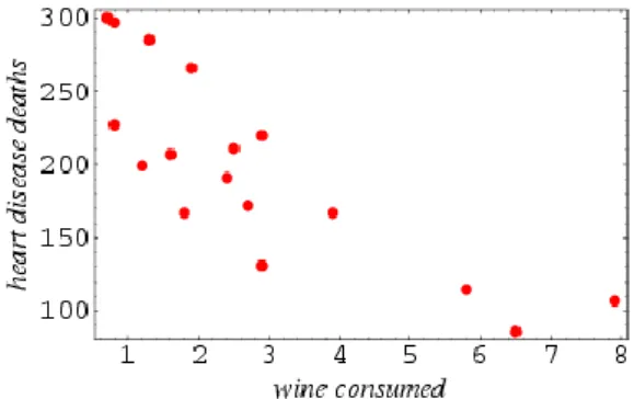
Dimensionality of a problem in information visualization refers to the number of attributes, or more generally as variables, that presents in the data to be visualized [2]. For one-dimensional data, which is also known as univariate data, consists of only one attributes, such as a collection of houses characterized by the cost. They can be visualized effectively by traditional tools like table and histogram. Interpretation of two-dimensional or bivariate data usually utilizes the x-y coordinates of a 2D space. A conventional approach is to plot one variable against the other called scatterplot, see Figure 2.1.
Figure 2.1: A scatterplot illustrating wine consumption against deaths from heart disease. [8]
Technically, multivariate data, also termed hypervariate data, is defined for a high dimensionality of three or above. However, as three-dimensional space are what we are living in, three-dimensional or trivariate data is often entertained separately. Modeling the data in a 3D space is the most straightforward way, but problems arise with displaying it in a two-dimensional representation [2]. It is hard to compare two points along the same axis, see Figure 2.2(a). A feasible solution, as shown in Figure 2.2(b), is to project the points onto pairs of axes in a two-dimensional scatterplot. 3D surfaces such as Figure 2.3(a) also encountered the same difficulty [2], where the minimum value can only be obtained after altering the view as in Figure 2.3(b). Obviously, orientation becomes crucial when dimensionality increases and proper interaction should be able to tackle this problem.
(a) (b)
Figure 2.2: (a) A 3D scatterplot, (b) Projection of the points in (a) onto two of the axes [9].
(a) (b)
The conceptual boundary between low and high dimensionality is not always precisely stated [11]. High-dimensional data is used in a loose manner; it can be arbitrarily defined, but it usually depicts a dimensionality of more than four. It is important to observe that geometric projections in more than four-dimensional are ineffective to convey information to human, which is due to the significant differences to perceive between low and high dimensionality.
2.2
Multidimensional and Multivariate
The terms multidimensional and multivariate are often used vaguely. Strictly speaking, multidimensional refers to the dimensionality of the independent dimensions while multivariate refers to that of the dependent variables [12]. The more appropriate term for multivariate data visualization should be multidimensional multivariate data visualization [13]. Nevertheless, a set of multivariate data is in high dimensionality and can possibly be regarded as multidimensional because the key relationships between the attributes are generally unknown in advance. The multidimensional property is therefore implied in common usage.
For convenience, the term attributes denote both independent dimensions and dependent variables. It also worth noting that multivariate data visualization is rather generic and does not categorize itself clearly between information visualization and scientific visualization.
3. Visualization Techniques
3.1
Classifications
Keim and Kriegel [14] [15] divided visual data exploration techniques for multidimensional multivariate data into six classes, namely geometric, icon-based, pixel-oriented, hierarchical, graph-based and hybrid techniques. We will adopt this taxonomy and tailor it to multivariate data visualization techniques, which are classified into four broad categories according to the overall approaches taken to generate resulting visualizations [11]: Geometric projection, pixel-oriented techniques, hierarchical display and iconography. They are elaborated in the following sections. Some representative techniques in each group are described in detail.
3.2
Geometric Projection
Geometric projection techniques aim at finding informative projections and transformations of multidimensional datasets [14]. It may map the attributes to a typical Cartesian plane like scatterplot, or more innovatively to an arbitrary space such as parallel coordinates.
Methods fall in this category are good for detecting outliers and correlation amongst different dimensions, and handling huge datasets when appropriate interaction techniques are introduced [15]. Intrinsically all data attributes are treated equally, but we must be aware that all dimensions may not be perceived equally [2]. As the order in which axes are displayed affects our perception [14], rearrangement is important if the display should not be biased. Another potential problem is visual cluttering and record overlapping [14] which overwhelms the user’s perception capabilities due to the high dimensionality or the large size of the data. Some typical techniques using geometric projection are discussed next.
3.2.1
Scatterplot Matrix
Scatterplot is used for bivariate discrete data in which two attributes are projected along the x-y axes of the Cartesian coordinates. Scatterplot matrix is an extension for multidimensional data where a collection of scatterplots is organized in a matrix simultaneously to provide correlation information among the attributes, see Figure 3.1. We can easily observe patterns in the relationships between pairs of attributes from the matrix, but there may be important patterns in higher dimensions which are barely recognized in it [17]. Another limitation is that it becomes chaotic when the number of points, that is the number of data items, is too large.
Figure 3.1: A scatterplot matrix for 5-dimensional data of 400 automobiles [17].
Fortunately the technique of brushing [18] can be applied to address the above problem. Brushing aims interpretation by highlighting a particular n-dimensional subspace in the visualization [13], that is, the respective points of interested are colored or highlighted in each scatterplot in the matrix. In Figure 3.1, automobiles are color-coded by the number of cylinders. Manufacturers can analyze the performance of the cars based on the number of cylinders for improvements, while customers can decide how many cylinders they need in order to suit their needs.
3.2.2
Prosection Matrix
Prosection was first introduced by Furnas and Buja [19]; Tweedie and Spence [20] later extended it to prosection matrix which supports a higher dimensionality. A typical prosection is shown in Figure 3.2(a). In the simplest sense, prosection is the orthogonal projections where the data items lie in the selected multidimensional range are colored differently [15]. The yellow rectangles in Figure 3.2(b) indicate the tolerances on parameter values, which is particularly useful for manufacturers to select appropriate parameter ranges. Yet it gives less information about the correlations between more than two attributes.
Figure 3.2: (a) A prosection, (b) A prosection matrix [21].
3.2.3
HyberSlice
Like the scatterplot and prosection matrix, HyperSlice [22] has a matrix graphics representing a scalar function of the variables [23], see Figure 3.3. This method targets at continuous scalar functions rather than discrete data. The most significant improvement over scatterplot is the interactive data navigation around a user defined focal point [23]. An enhanced HyperSlice was also proposed [24] which incorporate the concept of display resolution supported by space projection, together with the concept of data resolution provided by wavelets to form a powerful multiresolution visualization system.
(a) (b)
3.2.4
Hyberbox
Hyperbox [25] works similarly with the above techniques, except that the plots are now constructed as n-dimensional box instead of a matrix, as shown in Figure 3.5. The box is depicted in two dimensional because it is impossible to model the box exactly in an n-dimensional space. Hyberbox is a more powerful tool as it is possible to map variables to both size and shape of the face. It also allows emphasizing or de-emphasizing some variables [23]. However, the length and orientation are arbitrary which may convey the wrong information as it violates the “banking to 45 degrees” principle [26].
Figure 3.5: (a) A hyberbox [23]. Figure 3.6: Parallel coordinates [17].
3.2.5
Parallel Coordinates
Parallel coordinates [27] [28] [29] is a well-know technique where attributes are represented by parallel vertical axes linearly scaled within their data range. Each data item is represented by a polygonal line that intersects each axis at respective attribute data value, see Figure 3.6.
Parallel coordinates can be used to study the correlations among attributes by spotting the locations of the intersection points [23]. Also, they are effective for revealing the data distributions and functional dependencies. Nevertheless, one major limitation is the limited space available for each parallel axis. Visual clutter can severely hamper the user’s ability to interpret and interact with the visualizations [11]. Similar problem arises when the dimensionality of the data is too high that the axes are packed very closely. Same as the previous techniques, brushing may be applied to aid interpretation.
Circular Parallel Coordinates [30] is one of the variations adopting a radial arrangement of the axes, as illustrated in Figure 3.7. Hierarchical Parallel Coordinates [31] is an extension that targets at large datasets. It displays the aggregation information derived from a hierarchical clustering of the data [11]. These clusters are displayed at different levels of abstraction with proximity-based coloring and structure-based brushing [32], see Figure 3.8.
Figure 3.7: Circular Parallel coordinates [30].
Figure 3.8: Hierarchical Parallel Coordinates with different level of abstractions [31].
3.2.6
Andrews Curve
Andrews Curve [33], as shown in Figure 3.9, plots each data item as a curved line, which is similar to a Fourier transform of a data point [30]. Close points result similar curves and curves for distant points are distinct, which is useful for detecting clusters and outliers [34]. It can cope with many dimensions but is computationally expensive to display large datasets.
3.2.7
Radical Coordinates Visualization
Radical Coordinates Visualization [30] is similar to parallel coordinates in spirit, in which n lines emanate radically from the center of the circle and terminate at the perimeter, as shown in Figure 3.10. Each line is associated with one attribute; spring constants attached to the data attribute values define the positions of the data points along the lines. Points with approximately equal or similar dimensional values lie closer to the center.
3.2.8
Star Coordinates
Star coordinates [35] is an extension of typical scatterplots to higher dimensions. Data items are presented as points and attributes are represented by the axes arranged on a circle. Initially, the angles between the axes are equal and all axes have the same length.
Users can apply scaling transformations to change the length of an axis, which increases or decreases the contribution of an attribute. It also provide rotation transformations that change the direction of an axis, so the angles are no more equal and thus making an attribute more or less correlated with other attributes. An example of star coordinates after transformation is shown in Figure 3.11.It has been found to be useful in gaining insight into hierarchically clustered datasets and for multi-factor analysis for decision-making.
Figure 3.9: Andrews Curves [30].
Figure 3.10: Radical Coordinates Visualization [30].
Figure 3.11: Star Coordinates with transformations [35].
3.2.9
Table Lens
In table lens [36], each row represents a data item and the columns refer to the attributes. Each column is viewed as a histogram or as a plot, see Figure 3.12. Table lens was motivated by the regularity nature of traditional tables, where information along rows or columns is interrelated and can be interpreted as a coherent. It therefore takes advantage in using a concept which we are familiar with. It allows users to spot relationships, analyze trends in data, make assumptive correlations, easily view and manipulate the entire datasets.
Figure 3.12: An example of table lens from Inxight [37].
3.3
Pixel-Oriented Techniques
The second category for multivariate data visualization is pixel-oriented techniques. The idea is to represent an attribute value by a pixel based on some color scale. For an n-dimensional dataset, n colored pixels will be needed to represent one data item, with each attribute values being placed in separate sub-windows, as illustrated in Figure 3.13.
We can further divide these techniques into two subgroups, query-independent and query-dependent. Query-independent techniques are favored by data with a natural ordering according to one attribute, while query-dependent visualizations are more appropriate if the feedback to some query is of interest [14]. For the latter, the distances of attribute values to the query, instead of the absolute values, are mapped to colors. Correlations, functional dependencies and other relationships between attributes may be detected by relating corresponding regions in the multiple windows [14]. Moreover, as each data item is uniquely mapped to a pixel, record overlap and visual cluttering are not likely [11].
Figure 3.13: Pixel-based visualization of 6-dimensional data [15].
3.3.1
Space Filling Curve
Space Filling Curves are query-independent that provides a better clustering of closely related data items [14]. Some well-known examples are curves by Peano and Hilbert [38] [39] and Morton [40]. For multivariate data, curves of particular attributes are display in separate windows, as shown in Figure 3.14(a) and (b).
(a) (b)
(c)
3.3.2
Recursive Pattern
Recursive Pattern [41] is another query-independent which is based on generic recursive scheme to allow users to influence the arrangement of data items [14]. The arrangement of lines and columns is performed iteratively and recursively; the elements to be arranged at level i are the patterns resulting from level i-1. Similarly, recursive pattern of each attribute is shown in a single window, as illustrated in Figure 3.14(c).
3.3.3
Spiral and Axes Techniques
Spiral and axes techniques are both query-dependent. Spiral technique [42] arranges the pixels in spiral form according to the overall distance from the query, as depicted in Figure 3.15(a). The yellow center represents the data items satisfying the user specified query. Axes technique [42] improves the spiral one by including feedback on displacement. Pixels are arranged in partial spirals in each quadrant, that is, two attributes are assigned to the axes and data items are arranged according to the displacement as shown in Figure 3.15(b).
For query-dependent techniques, an additional window, like the top left one in Figure 3.15(c) and (d), is provided for overall distance or displacement. By relating corresponding regions in the windows, users can perceive multidimensional clusters or correlations [14].
(a) (b)
i
j
(c) (d)
Figure 3.15: (a) Spiral arrangement, (b) Partial spiral arrangement, (c) Spiral technique result of an 8-dimensional dataset, (d) Axes technique result of the same dataset [15].
3.3.4
Circle Segment
The design of circle segment [43] is to assign attributes on the segments of a circle. Data items are arranged within a segment so that a single data item appears in the same position at different segments [11]. The ordering and colors of the pixels are similarly determined by their overall distance to the query. Examples of circle segments are shown in Figure 3.16.
(a) (b)
Figure 3.16: (a) Circle segment arrangement for 8-diemensaionl data [15], (b) An example of circle segments [7].
3.3.5
Pixel Bar Chart
Pixel bar chart [44], derived from regular bar chart, presents data values directly instead of aggregating them into a few data values. Bars can be conventional histogram which plots one attributes against its values as shown in Figure 3.17, or x-y diagram that plots one attribute against another as illustrated in Figure 3.18. Each data item is represented by a single pixel and is placed in the bars accordingly. Ordering within the bars is determined by two additional attributes. Pixel color can be used to encode the values of one attributes.
For higher-dimensional data, multi-pixel bar charts are proposed, see Figure 3.18. Charts are duplicated and different attribute is colored-coded for each chart. Thus the same data item has the same relative position within each of the corresponding bars for detecting correlations.
(a) (b)
Figure 3.18: Multi-pixel bar chart with color encoding different attributes [44].
3.4
Hierarchical Display
Hierarchical techniques subdivide the data space and present subspaces in a hierarchical fashion [14]. Attributes are treated differently, with different mappings producing different views of the underlying data. Therefore interpretation of resulting plots requires training [11]. The techniques lay in this category concern mainly hierarchical data, or data in which several attributes are more important to users or of more interest.
3.4.1
Hierarchical Axis
In hierarchical axis [45] [46] [47], axes are laid out horizontally in a hierarchical fashion as illustrated in Figure 3.19(a). This technique can plot many attributes in one screen [23]. One simple example is the histograms within histograms plot. A matrix version, as shown in Figure 3.19(b), is also introduced to enhance perception similar to scatterplot matrix.
(a) (b)
3.4.2
Dimensional Stacking
Dimensional stacking [48], also called general logic diagrams, is a variation of hierarchical axis [23]. It partitions the data space into 2-dimensional subspaces which are stacked into each other [15], as depicted in Figure 3.18. Those important attributes should be chosen for the outer levels. This technique is especially adequate for discrete categorical or binned ordinal values. A major advantage of dimensional stacking over hierarchical axis is that no aggregation function is needed to plot the data, such as the previous case of histogram [23].
(a) (b)
Figure 3.18: (a) Partition of dimensional stacking, (b) An example [15].
3.4.3
Worlds Within Worlds
Another well-know hierarchical technique is worlds within world, or n-vision [49]. The data space is now subdivided into 3-dimenstional subspaces. It generates an interactive hierarchy display, instead of the static objects in the previous one, by using powerful 3D rendering [23]. It allows the exploration of n-dimensional function spaces, but could also be adapted to n-dimensional datasets [30]. Figure 3.19 shows an example that encodes 5-dimenisonal data.
3.4.4
Treemap
Treemap [51], as shown in Figure 3.20, uses a hierarchical partitioning of the screen into regions, depending on the attribute values. The sizes of the nested rectangles represent the attribute values, which provide extra information over simple mapping of dimensions only. The color of the regions may encode an additional attribute. Treemap is suitable to obtain an overview on large datasets with multiple ordinal attributes [15]. Moreover, it subdivides the display in a space-filling manner that fully utilizes the available display space [53].
3.5
Iconography
Iconographic or icon-based techniques map each multidimensional data item to an icon, or more specifically a glyph. The visual features vary depending on the data attribute values [11]. Several graphical parameters are usually contained in an icon, which makes it possible to handle multidimensional data. Besides, observations of graphical features are pre-attentive which is welcomed by human. However, unlike geometric techniques that treat all the dimensions equally, some features in glyphs are more salient than others [11], adjacent elements are easier to be related and accuracy of perceiving different graphical attributes varies between humans tremendously. It thereby introduces biases in interpreting the result.
3.5.1
Chernoff Faces
Chernoff face visualization [54] is probably the most famous in iconography. Two attributes are mapped to the 2D position of a face and remaining attributes are mapped to its properties of the face, for instance, the shape of nose, mouth, eyes and that of the face itself, as illustrated in Figure 3.21. One of the shortcomings is that different visual features are not quite comparable to each other [11]. It is also suggested that Chernoff faces can only visualize a limited amount of data items [14]. One common issue to all multidimensional icons, including Chernoff faces, is that the semantic relation to the task has significant impact on the perceptive effectiveness [2]. Yet it will then very much depend on the application domain.
(a) (b)
3.5.2
Star Glyph
There are many variants in the glyph family for displaying multidimensional data; star plot [56] is one of the most widely used glyphs. The dimensions are represented as equal angular axes radiating from the center of a circle [30], with an outer line connecting the data value points on each axis, as depicted in Figure 3.22(b). Each data item is presented by one star glyph. They are helpful for multivariate datasets of moderate size, but their primary weakness is that the display becomes overwhelming when the number of data items increases. Star plots can be further combined with other glyphs to encode extra information, an example incorporating the traditional box-and-whisker plots is shown in Figure 3.22(c).
(a) (b)
(c)
Figure 3.22: (a) Construct a star plot [57], (b) Group of star glyphs [30], (c) Box plot stars [58].
3.5.3
Stick Figure
Stick figure [59] is another classical icon-based technique that again maps two attributes to the display axes and the remaining to the rotation angle, length, thickness or color of the limbs, as depicted in Figure 3.23(a). When the data items are relatively dense with respect to the display dimensions, the packed icons exhibit some texture patterns that vary according to the data features, which are detected by pre-attentive perception [14]. However, the visual discernment of an important pattern is highly dependent upon the selection of an appropriate graphical attribute. This selection process is therefore deterministic and can a bottleneck [23].
(a) (b)
(c)
Figure 3.23: (a) Stick figure family [23], (b) 5D image data using stick figures, (c) Part of (b) in original size [60].
3.5.4
Shape Coding
Shape coding [61] visualizes data using small arrays of pixels. Each data item is represented by one such array, and the pixels are mapped to a color scale according to the attribute values, see Figure 3.24. Pixels in the array are placed in the form of square or rectangle and the arrays are arranged successively in a line-by-line fashion [14]. These arrays can contain an arbitrary number of pixels, making it possible for multidimensional data visualization.
(a) (b)
Figure 3.24: (a) Shape coding array [15], (b) An example [61].
3.5.5
Color Icon
Color icon [62] is a combination of the pixel-based spiral axes and icon-based shape coding techniques. Pixels are replaced by arrays of color fields that represent the attribute values similar to shape coding, as illustrated in Figure 3.25(c). Color, shape, size, orientation, boundaries and area sub-dividers can all be used to map the multidimensional data [23]. Color icon therefore merges color, shape and texture perception for iconographic integration [62].
(a) (b)
(c)
Figure 3.25: (a) 5D image data using color icons, (b) Part of (a) in original size [60], (c) Color icon scheme [15].
3.5.6
Texture
When large multidimensional data is presented in icons, such as stick figures and color icons mentioned above, it produces some textures which allow users to gain insight into the overall relationships between attributes, in addition to individual data items encoded by the icons respectively. With the recent advance in texture synthesis techniques [63] [64], it is now feasible to apply textures directly in multivariate data visualization.
Richly detailed and varying texture patterns have vast potential in visualizing multivariate data. Ware and Knight [65] conducted a pioneer vision research on using texture for information display. They identified three dominant visual dimensions of textures, namely orientation, size and contrast. Nevertheless the dimensionality of visual texture is very high, other dimensions include but not limit to hue, luminance, scale, regularity, periodicity, directionality, homogeneity, transparency, fuzziness and level of abstraction.
Among all, Interrante [66] proposed to harness natural textures of multivariate data visualization. Figure 3.26 shows a hand-crafted example encoding three-dimensional data with one dimension of color and two dimensions of texture. Tang et al. [67] applied natural near-regular textures to visualize weather data with multi-layer controllable texture synthesis. Additional attributes can be mapped to the foreground texture that is overlaid upon the background texture. Figure 3.27 shows one of the resulting visualizations.
Figure 3.27: Texture synthesis result for large regions in China [67].
Healey et al. have been working on methods for visualizing large, complex and multidimensional datasets [68] [69] [70]. Apart from the previous approach harnessing natural and photographic textures, they proposed from a completely different direction of using nonphotorealistic textures with perceptually-based brush strokes [71]. They used painted brush strokes, as shown in Figure 3.28, to represent multidimensional data elements. Each data attribute is mapped to a specific nonphotorealistic property such as color, orientation, coverage, size, coarseness and weight. The attributes values can thus be identified from the different visual appearances of the brush strokes.
The major advantage of using textures in multivariate data visualization is that they contain various visual dimensions that human can distinguish effectively and pre-attentively. Besides, the outcomes are generally more engaging and aesthetic that are more attractive and favorable, independent of what type of textures are being used. But problems remain in finding a suitable mapping from data attributes to texture features. Contrast illusions are also induced when we are comparing the scale and orientation of textures [1], which may cause misperception of data.
4. Discussion and Conclusion
In this survey, we reviewed some important techniques for multivariate data visualization. In section 1, we presented the motivations and challenges of visualizing high-dimensional multivariate data. A brief terminology on the topic was introduced in section 2, with an emphasis on dimensionality and the concept of multidimensional multivariate data. In section 3, we categorized multivariate data visualization techniques into four classes, namely geometric projection, pixel-oriented techniques, hierarchical display and iconography, based on a scheme proposed by Keim and Kriegel for general information visualization techniques. We aimed at providing a comprehensive overview on these techniques, which is arguable on the basis of their major advantages and limitations.
Geometric projection techniques were long established before the field of information visualization actually emerged. We are too familiar with the Cartesian space; it does not require us much effort to understand the representations of such techniques. However, it becomes problematic when the dimensionality of the data increases, as we can only map three dimensions to a 3D space.
Pixel-oriented techniques encode each data item as pixels. The corresponding pixels appear at the same position in each respective window. With suitable rearrangement, user may observe the inter-relationships between attributes, trends and patterns in the underlying data. Hierarchical displays are derived from the fundamental concept of hierarchical trees. They are very effective in visualizing hierarchical data, which is also their limitation. The outcomes of pixel-oriented techniques and hierarchical display are not as straightforward as those of geometric projection do; training may be required in order to understanding the visualizations. Iconography uses a multidimensional icon, or glyph, as the unit of visualization. A glyph has numerous graphical properties that data attributes can map to. When the glyphs, which are essentially data items, are densely packed together, it produces some texture patterns. Users are thus able to study the overall features and relationships in the data. While color has been used extensively to encode an addition dimension, it may be wise to replace its role by textures that obviously provide more graphical attributes for higher dimensional data.
With the information explosion in the last decade, people are now able to access huge amount of data easily from the internet; at the same time companies and institutions keep growing their large databases. Some kind of information, which could be financially, academically or even personally useful, is certainly under the veil of the impersonal data.
A picture is worth a thousand words. We believe multivariate data visualization has it vantage in helping us to gain insights into the terabyte data, as well as recognize the hidden correlations between attributes, which is beneficial to individuals, organizations, and possibly the society.
Bibliography
[1] C. Ware, Information Visualization: Perception for Design, Morgan Kaufmann Publishers, 2004.
[2] R. Spence, Information Visualization, Addison Wesley, ACM Press, 2000.
[3] S. Wehrend and C. Lewis, “A Problem-Oriented Classification of Visualization Techniques”,Proceedings of the 1st IEEE Conference on Visualization '90, pp.139-143, 1990.
[4] G. G. Grinstein and M. O. Ward, “Introduction to Data Visualization”, Information Visualization in Data Mining and Knowledge Discovery, Morgan Kaufmann Publishers, pp.21-45, 2001.
[5] J. J. van Wijk, “Views on Visualization”, IEEE Transactions on Visualization and Computer Graphics, vol.12, no.4, pp.421-433, 2006.
[6] C. G. Healey, “Perception in Visualization”, Department of Computer Science, North Carolina State University, available at: http://www.csc.ncsu.edu/faculty/healey/PP/, 2005.
[7] D. A. Keim, “Designing Pixel-Oriented Visualization Techniques: Theory and Applications”, IEEE Transactions on Visualization and Computer Graphics, vol.6, no.1, pp.59-78, 2000.
[8] D. S. More and G. P. McCabe, Introduction to the Practice of Statistics, W. H. Freeman, 1999, extracted from Wolfram MathWorld at:
http://mathworld.wolfram.com/ScatterDiagram.html.
[9] P. H. Hsu, Y. H. Tseng, “Data Exploration and Analysis of Hyperspectral Images: Visualization and Symbolic Description”, Proceedings of the 23rd Asia Conference on Remote Sensing, 2002.
[10] Screenshots from 3D Function Grapher by B. Kaskosz, Department of Mathematics, University of Rhode Island, available at:
http://www.math.uri.edu/~bkaskosz/flashmo/graph3d/, 2004.
[11] M. C. F. de Oliveira and H. Levkowitz, “From Visual Data Exploration to Visual Data Mining: A Survey”, IEEE Transactions on Visualization and Computer Graphics, vol.9, no.3, pp.378-394, 2003.
[12] R. D. Bergeron, W. Cody, W. Hibbard, D. T. Kao, K. D. Miceli, L. A. Treinish and S. Walther, "Database Issues for Data Visualization: Developing a Data Model", Proceedings of the IEEE Visualization '93 Workshop on Database Issues for Data Visualization, Lecture Notes in Computer Science, vol.871, Springer-Verlag, pp.3-15, 1994.
[13] P. E. Hoffman and G. G. Grinstein, “A Survey of Visualizations for High-Dimensional Data Mining”, Information Visualization in Data Mining and Knowledge Discovery, Morgan Kaufmann Publishers, pp.47-82, 2001.
[14] D. A. Keim and H.-P. Kriegel, “Visualization Techniques for Mining Large Databases: A Comparison”, IEEE Transactions on Knowledge and Data Engineering, vol.8, no.6, pp.923-938, 1996.
[15] D. A. Keim, “Visual Techniques for Exploring Databases”, Proceedings of the 3rd International Conference on Knowledge Discovery and Data Mining Tutorial Program, available at: http://www.informatik.uni-halle.de/~keim/PS/KDD97.pdf, 1997.
[16] W. S. Cleveland, Visualizing Data, AT&T Bell Laboratories, Murray Hill, NJ, Hobart Press, Summit NJ, 1993.
[17] “Visualizing Higher Dimensional Data” from the MathWorks, available at: http://www.mathworks.com/products/demos/statistics/mvplotdemo.html, 2006.
[18] R. A. Becker and W. S. Cleveland, “Brushing Scatterplots”, Technometrics, vol.29, no.2, pp.127-142, 1987.
[19] G. W. Furnas and A. Buja, “Prosection Views: Dimensional Inference through Sections and Projections”, Journal of Computational and Graphic Statistics, vol.3, no.4, pp.323-353, 1994.
[20] L. Tweedie and R. Spence, “The Prosection Matrix: A Tool to Support the Interactive Exploration of Statistical Models and Data”, Computational Statistics, vol.13, pp.65-76, 1998.
[21] B. Spence, “The Acquisition of Insight”, available at:
http://www.ee.ic.ac.uk/research/information/www/Bobs.html, 1990.
[22] J. J. van Wijk and R. van Liere, “HyperSlice: Visualization of Scalar Functions of Many Variables”, Proceedings of the 4th IEEE Conference on Visualization ’93, pp.119-125, 1993.
[23] P. C. Wong and R. D. Bergeron, “30 Years of Multidimensional Multivariate Visualization”, Scientific Visualization Overviews, Methodologies, and Techniques, IEEE Computer Society Press, pp.3-33, 1997.
[24] P. C. Wong, A. H. Crabb and R. D. Bergeron, “Dual Multiresolution HyperSlice for Multivariate Data Visualization”, Proceedings of IEEE Symposium on Information Visualization ’96, pp.74-75, 1996.
[25] B. Alpern and L. Carter, “Hyperbox”, Proceedings of the 2nd IEEE Conference on Visualization ’91, pp.133-139, 1991.
[26] W. S. Cleveland, M. E. McGill and R. McGill, “The Shape Parameter of a Two-Variable Graph”, Journal of American Statistical Association, vol.38, pp.289-300, 1993.
[27] A. Inselberg, “Multidimensional Detective”, Proceedings of the IEEE Symposium on Information Visualization, pp.100-107, 1997.
[28] A. Inselberg, “The Plane with Parallel Coordinates”, The Visual Computer, vol.1, pp.69-91, 1985.
[29] A. Inselberg and B. Dimsdale, “Parallel Coordinates: A Tool for Visualizing Multidimensional Geometry”, Proceedings of the 1st IEEE Conference on Visualization ’90, pp.31-375, 1990.
[30] P. E. Hoffman, “Table Visualizations: A Formal Model and Its Applications”, Doctoral Dissertation, Computer Science Department, University of Massachusetts at Lowell, 1999.
[31] Y.-H. Fua, M. O. Ward and E. A. Rundensteiner, “Hierarchical Parallel Coordinates for Exploration of Large Datasets”, Proceedings of the IEEE Conference on Visualization ’99, pp.43-50, 1999.
[32] Y.-H. Fua, M. O. Ward and E. A. Rundensteiner, “Navigating Hierarchies with Structure-Based Brushes”, Proceedings of the IEEE Symposium on Information Visualization, pp.58-164, 1999.
[33] D. F. Andrews, “Plots of High-Dimensional Data”, Biometrics, pp.69-97, 1972. [34] W. Basalaj, “Multivariate Visualization Techniques”, available at:
http://www.pavis.org/essay/multivariate_visualization_techniques.html, 2001.
[35] E.
Kandogan, “Star Coordinates: A Multidimensional Visualization Technique
with Uniform Treatment of Dimensions”,
Proceedings of the IEEE Symposium
on Information Visualization
, Late Breaking Hot Topics, 2000.
[36] R. Fao and S. K. Card, “The Table Lens: Merging Graphical and Symbolic Representations in an Interactive Focus + Context Visualization for Tabular Information”, Proceedings of the SIGCHI Conference on Human Factors in Computer Systems: Celebrating Interdependence, pp.318-322, 1994.
[37] G. Waloszek, “Table Lens”, available at:
http://www.sapdesignguild.org/community/book_people/visualization/controls/TableLen s.htm, 2004.
[38] G. Peano, “Sur une courbe qui remplit toute une aire plaine”, Mathematcis Annalen, vol.36, pp.157-160, 1890.
[39] D. Hilbert, “Ü ber stetige Abbildung einer Linie auf ein Flächenstück”, Mathematics Annalen, vol.38, pp.459-460, 1891.
[40] G. M. Morton, “A Computer Oriented Geodetic Data Base and a New Technique in File Sequencing”, Technical Report, IBM Ltd, 1966.
[41] D. A. Keim, H.-P. Driegel and M. Ankerst, “Recursive Pattern: A Technique for Visualizing Very Large Amounts of Data”, Proceedings of the 6th IEEE Conference on Visualization ’95, pp.279-286, 1995.
[42] D. A. Keim and H.-P. Kriegel, “VisDB: Database Exploration using Multidimensional Visualization”, IEEE Transactions on Computer Graphics and Applications, vol.14, no.5, pp.40-49, 1994.
[43] M. Ankerst, D. A. Keim, and H.-P. Kriegel, “Circle Segments: A Technique for Visually Exploring Large Multidimensional Data Sets”, Proceedings of the IEEE Conference on Visualization ’96, Hot Topic Session, 1996.
[44] D. Keim, M. Hao, U. Dayal, M. Hsu and J. Ladisch, “Pixel Bar Charts: A New Technique for Visualizing Large Multi-Attribute Data Sets without Aggregation”, Proceedings of the IEEE Symposium on Information Visualization 2001 (INFOVIS’01), pp.113-120, 2001.
[45] T. Mihalisin, E. Gawlinski, J. Timlin and J. Schwegler, “Visualizing a Scalar Field on an n-Dimensional Lattice”, Proceedings of the 1st IEEE Conference on Visualization ’90, pp.255-262, 1990.
[46] T. Mihalisin, J. Timlin and J. Schwegler, “Visualization and Analysis of Multi-Variate Data: A Technique for All Fields”, Proceedings of the 2nd IEEE Conference on Visualization ’91, pp.171-178, 1991.
[47] T. Mihalisin, J. Timlin and J. Schwegler, “Visualizing Multivariate Functions, Data, and Distributions”, IEEE Computer Graphics and Applications, vol.11, no.3, pp.28-35, 1991.
[48] J. LeBlanc, M. O. Ward and N. Wittels, “Exploring N-Dimensional Databases”, Proceedings of the 1st IEEE Conference on Visualization ’90, pp.230-237, 1990.
[49] S. Feiner and C. Beshers, “Visualizing n-Dimensional Virtual World with n-Vision”, Computer Graphics, vol.24, no.2, pp.37-38, 1990.
[50] S. Feiner and C. Beshers, “n-Visiona and AutoVisual”, available at:
http://www1.cs.columbia.edu/graphics/projects/AutoVisual/AutoVisual.html#Worlds_wi thin_worlds, 1993.
[51] B. Shneiderman, “Tree Visualization with Treemaps: A 2D Space-Filling Approach”, ACM Transactions on Graphics, vol.11, no.1, pp.92-99, 1992.
[52] B. Shneiderman, “Treemaps for Space-Constrained Visualization of Hierarchies”, available at: http://www.cs.umd.edu/hcil/treemap-history/, 2006.
[53] T. Schreck, D. Keim and F. Mansmann, “Regular TreeMap Layouts for Visual Analysis of Hierarchical Data”, Spring Conference on Computer Graphics SCCG, 2006.
[54] H. Chernoff, “The Use of Faces to Represent Points in k-Dimensional Space Graphically”, Journal American Statistical Association, vol.68, pp.361-368, 1973.
[55] L. Gonick and W. Smith, The Cartoon Guide to Statistics, Harper Perennial, pp.212, 1993. Extracted from Wolfram MathWorld at:
http://mathworld.wolfram.com/ChernoffFace.html.
[56] J. M. Chambers, W. S. Cleveland, B. Kleiner and P. A. Tukey, Graphical Methods for Data Analysis, Belmont, Wadsworth Press, 1983.
[57] V. Bategelj and A. Mrvar, “Visualization of Multivariate Data Using 3D and VR Presentations”, Indo-French Workshop on Symbolic Data Analysis and its applications, vol.1, pp.66-76, 1997, available at: http://vlado.fmf.uni-lj.si/vrml/paris.97/.
[58] R. Marmo, M. Valle and C. Zannoni, Introduzione alla Visualizzazione Scientifica, Editrice Il Rostro, 2006, available at: http://www.cscs.ch/~mvalle/Libro/immagini.html. [59] R. M. Pickett and G. G. Grinstein, “Iconographic Displays for Visualizing
Multidimensional Data”, Proceedings of the IEEE International Conference on Systems, Man and Cybernetics, vol.1, pp.514-519, 1988.
[60] Image Gallery, Institute for Visualization and Perception Research, University of Massachusetts at Lowell, available at: http://ivpr.cs.uml.edu/gallery/, 2006.
[61] J. Beddow, “Shape Coding of Multidimensional Data on a Microcomputer Display”, Proceedings of the 1st IEEE Conference on Visualization '90, pp.238-246, 1990.
[62] H. Levkowitz, “Color Icons: Merging Color and Texture Perception for Integrated Visualization of Multiple Parameters”, Proceedings of the 2nd IEEE Conference on Visualization ’91, pp.164-170, 1991.
[63] A. A. Efros and W. T. Freeman, “Image Quilting for Texture Synthesis and Transfer”, Proceedings of the 28th Annual Conference on Computer Graphics and Interactive Techniques ACM SIGGRAPH 2001, pp.35-42, 2001.
[64] L.-Y. Wei and M. Levoy, “Fast Texture Synthesis using Tree-Structured Vector Quantization”, Proceedings of the 27th Annual Conference on Computer Graphics and Interactive Techniques ACM SIGGRAPH 2000, pp.479-488, 2000.
[65] C. Ware and W. Knight, “Using Visual Texture for Information Display”, ACM Transactions on Graphics TOG, vol.14, no.1, pp.3-20, 1995.
[66] V. Interrante, “Harnessing Natural Textures for Multivariate Visualization”, IEEE Transactions on Computer Graphics and Applications, vol.20, no.6, pp.6-11, 2000. [67] Y. Tang, H. Qu, Y. Wu and H. Zhou, “Weather Data Visualization Using Natural
Textures”, Proceedings of the 10th International Conference on Information Visualization 2006, 2006.
[68] C. G. Healey and J. T. Enns, “Building Perceptual Textures to Visualize Multidimensional Datasets”, Proceedings of the IEEE Conference on Visualization ‘98, pp.111-118, 1998.
[69] C. G. Healey and J. T. Enns, “Large Datasets at a Glance: Combining Textures and Colors in Scientific Visualization”, IEEE Transactions on Visualization and Computer Graphics, vol.5, no.2, pp.145-167, 1999.
[70] C. Weigle, W. G. Emigh, G. Liu, R. M. Taylor, J. T. Enns and C. G. Healey, “Oriented Texture Slivers: A Technqiue for Local Value Estimation of Multiple Scalar Fields”, Proceedings Graphics Interface 2000, pp.163-170, 2000.
[71] C. G. Healey, L. Tateosian, J. T. Enns and M. Remple, “Perceptually Based Brush Strokes for Nonphotorealistic Visualization”, ACM Transactions on Graphics TOG, vol.23, no.1, pp.64-96, 2004.
![Figure 3.1: A scatterplot matrix for 5-dimensional data of 400 automobiles [17].](https://thumb-us.123doks.com/thumbv2/123dok_us/8747247.2372006/9.892.265.634.609.896/figure-a-scatterplot-matrix-for-dimensional-data-automobiles.webp)
![Figure 3.7: Circular Parallel coordinates [30].](https://thumb-us.123doks.com/thumbv2/123dok_us/8747247.2372006/12.892.150.760.104.390/figure-circular-parallel-coordinates.webp)
![Figure 3.10: Radical Coordinates Visualization [30].](https://thumb-us.123doks.com/thumbv2/123dok_us/8747247.2372006/13.892.189.705.601.897/figure-radical-coordinates-visualization.webp)
![Figure 3.19: N-Vision [50]. Figure 3.20: Treemap [52].](https://thumb-us.123doks.com/thumbv2/123dok_us/8747247.2372006/18.892.405.744.770.976/figure-n-vision-figure-treemap.webp)
![Figure 3.26: Hand-crafted example using textures to visualize 3D data [66].](https://thumb-us.123doks.com/thumbv2/123dok_us/8747247.2372006/22.892.185.707.708.1104/figure-hand-crafted-example-using-textures-visualize-data.webp)
![Figure 3.27: Texture synthesis result for large regions in China [67].](https://thumb-us.123doks.com/thumbv2/123dok_us/8747247.2372006/23.892.167.730.457.857/figure-texture-synthesis-result-large-regions-china.webp)
![Figure 3.28: Nonphotorealistic visualization of weather conditions [68].](https://thumb-us.123doks.com/thumbv2/123dok_us/8747247.2372006/24.892.159.743.341.826/figure-nonphotorealistic-visualization-of-weather-conditions.webp)
