Srf Theory Revisited” To Control Self-Supported Dynamic Voltage
Restorer (Dvr) For Unbalanced And Nonlinear Loads
Leela Sarvani Palukuru1, Mr.Y.Raja Babu2 1
PG Scholar, Pydah College of Engineering, Kakinada, AP, India.
2Assistant Professor, Pydah College of Engineering, Kakinada, AP, India. Abstract—In this paper a fuzzy controller based DVR is
proposed for the protection of the sensitive unbalanced nonlinear loads from sag/swell, distortion, and unbalance in supply voltage is achieved. A simple generalized algorithm based on basic synchronous reference frame theory has been developed for the generation of instantaneous reference compensating voltages for controlling a DVR. This novel algorithm makes use of the fundamental positive sequence phase voltages extracted by sensing only two unbalanced and/or distorted line voltages. In addition to this a fuzzy logic controller have been developed to reduce the % THD compared with the conventional method. The compensating voltages when injected in series with a distribution feeder by three single-phase H-bridge voltage-source converters A capacitor-supported DVR does not need any active power during steady-state operation because the injected voltage is in quadrature with the feeder current. The proposed control strategy is validated through simulation results with the help of MATLAB/SIMULINK software.
Index Terms— Dynamic voltage restorer (DVR), fuzzy logic controller, voltage-source converter (VSC)
I. INTRODUCTION
Under the generic name of custom power devices, a new group of devices is developed and used for improving the PQ in the distribution system. As per the standard such as the IEEE 519, a number of custom power devices are installed and used at the consumer premises to protect the critical loads. The dynamic voltage restorer (DVR), one of the aforementioned devices, is used for improving the PQ of the load terminal voltages against voltage sags, swells, transients, and harmonic distortions in the source voltages. A DVR is a voltage-source converter (VSC)-based power electronics device connected in series between the supply and the critical loads, which are to be protected from the supply-side voltage quality problems, other than outages, by injecting the required compensating voltage through DVR into the distribution line. A DVR can restore a balanced sinusoidal load voltage of desired amplitude even when the source voltage is unbalanced and/or distorted. The voltage injected by self supported DVR is in quadrature with the feeder current; hence, it does not need any active power during steady state.
However, its disadvantage is that, in case of the voltage sag/swell, the restored voltage may not be in phase with the pre-sag/pre-swell voltage. The self-supported DVR is used when the phase jump, caused by the quadrature voltage injection, is affordable.
The DVR is an important controller in the custom power park. The analysis, design, and voltage injection schemes of the self-supported DVR are discussed in [2], [10], and [11], and the different control strategies for the DVR have been developed in [8]–[17]. Control techniques based on synchronous reference frame (SRF) theory (SRFT), Adeline-based fundamental extraction, instantaneous symmetrical component theory, energy optimized control, PQR instantaneous power theory, symmetrical component estimation, etc., for the DVR are reported in the literature.
The DVR supported by a capacitor has become popular as a cost-effective solution for the protection of sensitive loads from the supply-side voltage quality problems. Currently, most of the research is on DVR dealing with the protection of balanced linear load; however, there are a few which are related to the protection of unbalanced and nonlinear loads.
In modern industries, power electronics-based drives such as the current-source-inverter-fed synchronous motor drive, thyristor converter-based dc motor drive, VSC-based induction motor drive, etc., are increasingly used whose performance and control largely depend upon the supply voltage quality. Moreover, these nonlinear industrial loads give rise to additional harmonic distortion in the supply voltage at the point of common coupling (PCC) due to the harmonic voltage drop into the feeder impedance, particularly when the feeder impedance is large.
In this paper a fuzzy controller based DVR is proposed for the protection of the sensitive unbalanced nonlinear loads from sag/swell, distortion, and unbalance in supply voltage is achieved. This novel algorithm makes use of the fundamental positive sequence phase voltages extracted by sensing only two unbalanced and/or distorted line voltages. The algorithm is general enough to handle linear as well as nonlinear loads. The self supported DVR maintains balanced sinusoidal load voltage with desired magnitude against any supply voltage quality problem even when the load is unbalanced and nonlinear in nature.
The algorithm based on instantaneous symmetrical components along with the complex Fourier transform to protect unbalanced and nonlinear load discussed in [17] is computationally demanding and requires huge memory space. The approach discussed here is comparatively simple as it needs only the extraction of the fundamental positive-sequence phase terminal voltages, thus making it computationally simpler with the least memory requirement. The proposed fundamental positive-sequence extractor requires the sensing of only two line voltages of supply.
sensing element. Moreover, it is able to extract three fundamental positive-sequence phase voltages irrespective of the distribution system configuration such as three-phase, four-wire or three-phase, three-wire system where the neutral is not available for sensing phase voltages.
In this paper, a hybrid structure of the self-supported DVR is considered in which a shunt capacitor filter is used to provide the low impedance path for higher order harmonics of the load currents. The DVR is realized by three single-phase H-bridge VSCs with a fuzzy logic controller.
II. CONTROL STRATEGY
The main aim of the DVR is to inject a required amount of compensating voltage in series with the supply to regulate the load terminal voltage. In this section, the proposed control algorithm is discussed with an ideal DVR model. The schematic diagram of DVR (ideal voltage sources) connected distribution feeder is shown in Fig. 1. A three-phase supply is represented by the star-connected three single-phase voltage sources (Vsa, Vsb, Vsc) along with their series source impedances (Za, Zb, Zc). To regulate the load voltages (VLa, VLb, VLc) to be balanced and sinusoidal against various PQ problems in the terminal voltages (Vta, Vtb, Vtc), DVR injects the required compensating voltages (VCa, VCb, VCc) in each phase. The practical implementation of a DVR using three single phase H-bridge VSCs along with a common dc capacitor is discussed later. The energy storage device is a capacitor, so the following condition is stipulated on the DVR.
• The DVR should not supply any real power in steady state. This implies that, in steady state, the phase difference between instantaneous DVR voltages and instantaneous line currents must be 90◦.
A. Balanced Linear Load
In this section, the algorithm is developed to compute instantaneous DVR voltages from the samples of instantaneous terminal voltages and line currents assuming balanced sinusoidal supply and balanced load. The schematic diagram of the DVR connected power system is shown in Fig. 1.
Fig. 1 Schematic diagram of DVR (ideal voltage sources) connected power system.
From Fig. 1,
Where vtk, vck, and v∗ Lk are the instantaneous terminal voltages, instantaneous DVR voltages, and instantaneous
reference load voltages, respectively. Moreover, k is the phase of the supply. Taking the line current as the reference frame, the above equation can be converted to SRF as
Note that, for zero DVR active power in steady state, VCshould be at 90◦to the line current, so in (2),vck contributes to the quadrature component vcq only and the terminal voltages are balanced and sinusoidal; therefore, there is no zero sequence component (vt0) present in (2). In (2), vtd can be computed from the instantaneous samples of terminal voltages as
As terminal voltages are balance and sinusoidal,vtd contains only the constant dc component, and from (2)
Moreover, to regulate the peak of the load voltage (ph-n) to
vLp,v∗Lq can be directly calculated as
After computingv∗Ld andvLq, the instantaneous reference load voltages can be computed as follows:
As the load is a balanced linear load, sinθand cosθused in (3) and (6) can be computed directly using instantaneous samples of load currents as
Where
From the calculated instantaneous reference load voltages using (6) and the samples of instantaneous terminal voltages, the instantaneous DVR voltages can be computed as per (1). The response of the DVR-connected balanced sinusoidal power system to compensate balanced sag and swell is discussed in Case 1 to validate the control algorithm just shown.
Moreover, it is required to regulate the amplitude of the load voltage to 1 p.u.
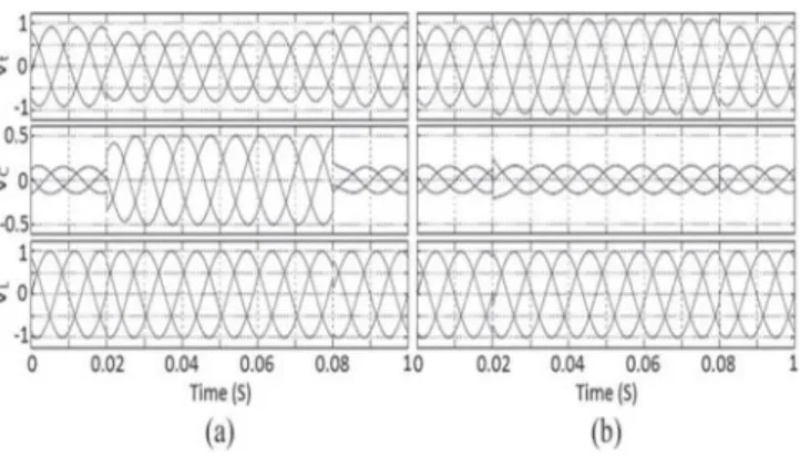
The DVR-connected power system response with the algorithm discussed earlier during balanced voltage sag is shown in Fig. 2(a). The terminal voltages (Vt), DVR voltages (VC), and load voltages (VL) are shown in Fig. 2(a) from top to bottom. It can be seen that the amplitude of the load voltages becomes equal to 1.0 p.u. as DVR is pressed into action at 0.0 s.
Fig. 2 DVR response for balanced sag and swell
Then, the balanced sag of 0.2 p.u. is introduced at 0.02 s, and it occurs for four cycles of ac mains as shown in Fig. 2(a). It can be seen that the amplitude of the load voltage is regulated to 1.0 p.u. by injecting a voltage VC
through DVR.
The DVR-connected power system response with 0.2 p.u. balance swell is shown in Fig. 2(b). In this case also, it can be seen that the amplitude of the load voltage is regulated to 1.0 p.u. The results shown in Case 1 validate the control algorithm to control DVR when the supply is balanced. However, one of the main reasons for the use of DVR is to produce harmonic free balanced sinusoidal load voltages even when the supply is unbalanced and/or distorted.
B. Unbalanced Linear Load
The algorithm discussed in the previous section will fail to compute the desired reference load voltages under the situation, where the unbalanced and/or distorted supply voltages feed the unbalanced load. There are two reasons for this: First, the load currents are not balanced, so sin θ and cos θ cannot be calculated from (7)–(9) directly, and second,vtd calculated from (3) does not only contain a constant component but also contains a varying component because terminal voltages are not balanced.
For the algorithm to work under such situation, the following conditions should be satisfied: 1) sinθ and cosθ
used in (6) should be sinusoidal in shape with their phase locked to fundamental positive-sequence load currents; this can be achieved using a phase-locked loop (PLL) over the load currents, and 2) fundamental positive-sequence components of terminal voltages should be used in the calculation of vtd instead of samples of unbalanced and/or distorted terminal voltages.
The unbalanced and/or distorted terminal voltages can be written as
Wherevtk1_fis the positive-sequence component ofvtk and
vtk_rest is the remaining portion containing the influence of unbalance and harmonics. The modification is thus to replacevta,vtb, andvtc in (3) byvta1_f,vtb1_f, andvtc1_f
, respectively.
To extract the fundamental positive-sequence terminal phase voltages, a novel fundamental positive-sequence extractor is proposed which requires the sensing of only two distorted and/or unbalanced terminal line voltages.
C. Fundamental Positive-Sequence Extractor
As the line voltages are the difference of different phase voltages (va− vb,vb− vc, andvc− va), the summation of three line voltages is always zero irrespective of whether three phase voltages are balanced and sinusoidal or unbalanced. Therefore, by sensing only two line voltages
vab andvbc, the third line voltagevca can be calculated as
vca =−(vab +vbc).(12)
If Park’s transformation is applied to three balanced sinusoidal line voltages vab, vbc, and vca using a PLL over the same line voltages, then it gives constant direct-axis component vd equal to the amplitude of line voltage, quadrature-axis component vq equal to zero, and zero-sequence component v0 equal to zero because line voltages are a positive sequence only without any harmonics. When line voltages are unbalanced and/or distorted, then, vd is composed of two parts: a constant component equal to the amplitude of positive-sequence line voltage and a varying component influenced by negative-sequence line voltage and harmonics. While vq and v0 are not of interest because here, the aim is to extract fundamental positive-sequence line voltages and bothvqand
v0 do not contain any information about positive-sequence line voltages, note that v0 is always zero when Park’s transformation is applied to the line voltages.
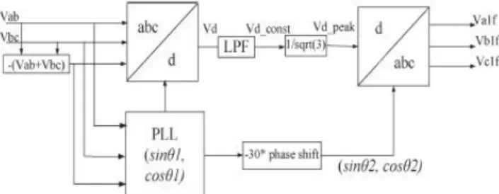
The direct-axis componentvd=vd_const +vd_var can be calculated using samples of line voltages with PLL over the same line voltages as
The amplitude of the fundamental positive-sequence line voltagevd_const is then extracted by passing
vdthrough a low pass filter (LPF) or moving average filter; LPF is advantageous when distorted line voltages contain inter-harmonics. After extractingvd_const, the amplitude of the fundamental positive sequence phase voltage vd_peak can be calculated as
The block diagram of the fundamental positive-sequence extractor is shown in Fig. 3.
Fig. 3 Block diagram of fundamental positive-sequence extractor
Case 2: In this case, unbalanced supply voltages with magnitudes of 1.15, 1, and 0.85 p.u. in phases a, b, and c, respectively, are considered in which the fifth and seventh harmonics have also been added with their amplitude being inversely proportional to their harmonic number. The load impedances in each phase are 2+j1.5 p.u., 2.5+j2 p.u., and 1+j2.5 p.u., respectively, and the other parameters are the same as that in Case 1. The DVR-connected power system response with the proposed fundamental positive-sequence extractor and modifications in the algorithm as discussed earlier is shown in Fig. 4.
Fig. 4 DVR response for unbalanced and distorted supply with unbalanced load
III. POWER CIRCUIT
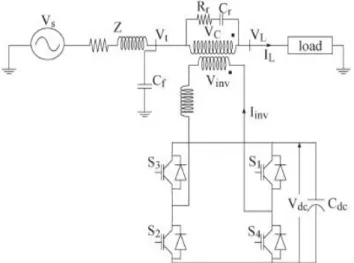
In the previous section, a response of DVR in different PQ problems with the developed control algorithm assuming DVR realized by ideal voltage sources is demonstrated. In this section, the power circuit of DVR is discussed. Practically, the DVR is realized by three single-phase H-bridge VSCs along with a common dc capacitor (Cdc) as shown in Fig. 5.
The three H-bridge VSCs are connected to each phase of the distribution feeder through the improved structure ripple filter (Lr, Cr,Rr) and an injection transformer. The injection transformer not only reduces the voltage requirement of the converter but also provides isolation between the converter and the distribution feeder. The shunt capacitor filter Cf is used to provide a low
impedance path to higher order harmonics of load currents when the load current is nonlinear. The operation of practical DVR with nonlinear load current is discussed in the next section.
To track the reference compensating voltages, an improved filter structure constant switching frequency hysteresis band controller [18] is used in this work. The main advantages of the band controller are unconditional stability, faster response and easy implementation compared to other controllers like carrier-based controllers, dead-beat control [17], state feedback control, combined feed-forward and feedback control, etc., which are based on complex mathematical computations and need much information about system parameters. Despite these advantages, the main disadvantage of the band controller compared to carrier-based controllers is variable switching frequency which may cause stress in the switches of the VSC, resulting in the deterioration of its life. The band controller has other drawbacks also like poor controllability, heavy filter currents, parabolic band voltage response, and frequent band violations due to the use of a conventionalLC filter which has a second-order characteristic equation.
The constant switching frequency hysteresis band controller with improved filter structure discussed in [18] preserves all the advantages of the band controller and also overcomes its drawbacks by improved filter structure and adaptive hysteresis band which gives constant switching frequency.
Fig. 5 DVR power circuit
The single-phase equivalent circuit of the DVR-connected system in Fig. 5 is shown in Fig. 6 to explain the basic principle of the hysteresis band controller. The reference compensating voltage for the DVR is calculated using the proposed algorithm. To inject this voltage in series with the distribution feeder, appropriate switching pulses for VSC are generated using the hysteresis band controller with hysteresis bandh. The VSC output voltage is made to track the reference voltages within upper and lower boundaries
above the upper boundary, the negative dc voltage is applied by turning switchesS3 andS4 on. The switching logic thus can be stated as given in Table I.
TABLE I
SWITCHING LOGIC OF VSC WITH HYSTERESIS BAND CONTROLLER
In order to improve the performance of the controller, an extra resistanceRr is connected in series with ac filter capacitor Cr as shown in Fig. 6. This resistance dominates the capacitive reactance at switching frequency. At switching frequency, the resistance Rr and combined inductive reactance of theLr and transformer are very large compared to the capacitive reactance of Cr. Thus, at switching frequency, this improved structure filter circuit behaves as an R− L circuit and gives a linear voltage variation within the band compared to the parabolic voltage given by the conventionalL− Cfilter circuit. Because of the linear response, this filter has less band violations and, hence, better controllability compared to the conventional filter.
Fig. 6 Single-phase equivalent circuit of DVR-connected system
Details of the design of filter components can be found in [18]. To make the switching frequency constant, the hysteresis band is made variable, and its value can be calculated as
Where
For given switching frequencyfsw, dc voltagevdc, total filter inductance (transformer inductance plus Lr), and filter resistor Rr, the value of K is a constant; hence, the variation of the band depends on the reference voltage.
In addition to the hysteresis band controller, an additional controller is required to correct the voltage in the dc-storage capacitor against the losses in the inverter and transformer, which may cause the capacitor voltage to fall. To correct these deviations, a small value of voltage in phase to the current must be injected by the DVR. To accomplish this, a simple discrete PI controller is introduced of the form
Where e(n) = vrefdc− vfdc(n) and vfdc(n) is the sensed instantaneous voltage across the capacitor passed through LPF. Now, (4) and (5) can be modified such that
The complete block diagram of the proposed control algorithm with all modifications is shown in Fig. 7.
Fig. 7 Complete block diagram of proposed control algorithm
Fig. 8 DVR response for balanced sag and swell
Fig. 9 DVR response for unbalanced and distorted supply with unbalanced load
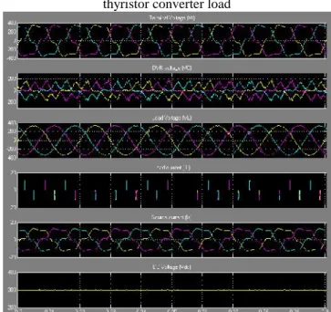
Fig. 10 Response of DVR without shunt capacitor filter for thyristor converter load
Fig. 11 Response of DVR with shunt capacitor filter for thyristor converter load
Fig. 13 Response of DVR during voltage sag
Fig. 14 Response of DVR with unbalanced and distorted supply
Fig. 15 Response of DVR with unbalanced and distorted supply with fuzzy logic controller
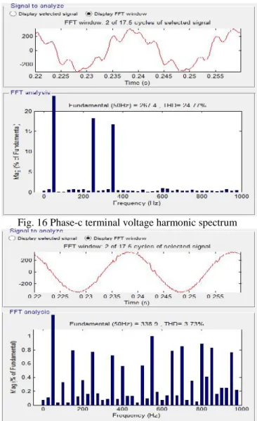
Fig. 16 Phase-c terminal voltage harmonic spectrum
Fig. 18 Phase-c load voltage harmonic spectrum with fuzzy logic controller
CONCLUSION
The performance of DVR with the proposed control algorithm has been evaluated for both the harmonic current source and the harmonic voltage source type of nonlinear loads with different supply voltage quality problems. A fundamental positive-sequence extractor has been proposed, which extracts three fundamental positive-sequence phase voltages by sensing only two unbalanced and/or distorted line voltages. It has been shown that, when load is nonlinear, only DVR, without a shunt capacitor filter, is not able to suppress the voltage spikes. The performance of the DVR has been observed to be satisfactory in all the cases. Moreover, it is shown that DVR with fuzzy logic controller is more effective than that of conventional system.
REFERENCES
[1] M. H. J. Bollen, Understanding Power Quality Problems: Voltage Sags and Interruptions. Piscataway, NJ, USA: IEEE Press, 2000.
[2] A. Ghosh and G. Ledwich,Power Quality Enhancement Using Custom Power Devices. London, U.K.: Kluwer, 2002. [3] R. C. Dugan, M. F. McGranaghan, and H. W. Beaty,
Electric Power Systems Quality, 2nd ed. New York, NY, USA: McGraw-Hill, 2006.
[4] H. Akagi, E. H. Watanabe, and M. Aredes,
Instantaneous Power Theory and Applications to Power Conditioning. Hoboken, NJ, USA: Wiley, 2007.
[5] A. Moreno-Munoz, Power Quality: Mitigation Technologies in a Distributed Environment. London, U.K.: Springer-Verlag, 2007.
[6] IEEE Recommended Practices and Recommendations for Harmonics Control in Electric Power Systems, IEEE Std. 519, 1993.
[7] A. Ghosh, “Performance study of two different compensating devices in a custom power park,” Proc. Inst. Elect. Eng.—Gen. Transmiss. Distrib., vol. 152, no. 4, pp. 521–528, Jul. 2005.
[8] P. Jayaprakash, B. Singh, D. P. Kothari, A. Chandra, and K. Al-Haddad, “Control of reduced rating dynamic voltage
restorer with battery energy storage system,” inProc. Power Syst. Technol. IEEE POWERCONOct.12–15, 2008, pp.1–8. [9] B. Singh, P. Jayaprakash, and D. P. Kothari, “Adaline based control of capacitor supported DVR for distribution systems,” J. Power Electron., vol. 9, no. 3, pp. 386–395, May 2009.
[10] A. Ghosh and A. Joshi, “A new algorithm for the generation of reference voltages of a DVR using the method of instantaneous symmetrical components,” IEEE Power Eng. Rev., vol. 22, no. 1, pp. 63–65, Jan. 2002.
[11] A. Ghosh and G. Ledwich, “Compensation of distribution system voltage using DVR,” IEEE Trans. Power Del., vol. 17, no. 4, pp. 1030–1036, Oct. 2002. [12] M. Vilathgamuwa, R. Perera, S. Choi, and K. Tseng, “Control of energy optimized dynamic voltage restorer,” in
Proc. IEEE IECON, 1999, vol. 2, pp. 873–878.
[13] S.-J. Lee, H. Kim, S.-K. Sul, and F. Blaabjerg, “A novel control algorithm for static series compensators by use of PQR instantaneous power theory,” IEEE Trans. Power Electron., vol. 19, no. 3, pp. 814–827, May 2004.
[14] M. I. Marei, E. F. El-Saadany, and M. M. A. Salama, “A new approach to control DVR based on symmetrical components estimation,” IEEE Trans. Power Del., vol. 22, no. 4, pp. 2017–2024, Oct. 2007.
[15] J. W. Liu, S. S. Choi, and S. Chen, “Design of step dynamic voltage regulator for power quality enhancement,”
IEEE Trans. Power Del., vol. 18, no. 4, pp. 1403–1409, Oct. 2003.
[16] A. K. Jindal, A. Ghosh, and A. Joshi, “Critical load bus voltage control using DVR under system frequency variation,” Elect. Power Syst. Res., vol. 78, no. 2, pp. 255– 263, Feb. 2008.
[17] A. Ghosh, A. K. Jindal, and A. Joshi, “Design of a capacitor-supported dynamic voltage restorer (DVR) for unbalanced and distorted loads,” IEEE Trans. Power Del., vol. 19, no. 1, pp. 405–413, Jan. 2004.
[18] S. Sasitharan and M. K. Mishra, “Constant switching frequency band controller for dynamic voltage restorer,”